RU2675103C1 - Device for distributing floating means on water attractions - Google Patents
Device for distributing floating means on water attractions Download PDFInfo
- Publication number
- RU2675103C1 RU2675103C1 RU2018118587A RU2018118587A RU2675103C1 RU 2675103 C1 RU2675103 C1 RU 2675103C1 RU 2018118587 A RU2018118587 A RU 2018118587A RU 2018118587 A RU2018118587 A RU 2018118587A RU 2675103 C1 RU2675103 C1 RU 2675103C1
- Authority
- RU
- Russia
- Prior art keywords
- opening
- water
- floating means
- floating
- tubing
- Prior art date
Links
- 238000007667 floating Methods 0.000 title claims abstract description 145
- XLYOFNOQVPJJNP-UHFFFAOYSA-N water Substances O XLYOFNOQVPJJNP-UHFFFAOYSA-N 0.000 title claims abstract description 111
- 239000012530 fluid Substances 0.000 claims description 12
- 238000005406 washing Methods 0.000 claims description 11
- 230000004807 localization Effects 0.000 claims description 6
- 230000004044 response Effects 0.000 claims description 4
- 239000007788 liquid Substances 0.000 claims description 3
- 239000000463 material Substances 0.000 claims description 3
- 239000013013 elastic material Substances 0.000 claims description 2
- 230000015572 biosynthetic process Effects 0.000 claims 1
- 238000012423 maintenance Methods 0.000 abstract description 3
- 238000000034 method Methods 0.000 abstract description 3
- 239000000126 substance Substances 0.000 abstract 1
- 238000005516 engineering process Methods 0.000 description 10
- 238000005259 measurement Methods 0.000 description 4
- 238000004891 communication Methods 0.000 description 2
- 238000010586 diagram Methods 0.000 description 2
- 238000000605 extraction Methods 0.000 description 2
- 230000005484 gravity Effects 0.000 description 2
- 238000007726 management method Methods 0.000 description 2
- 238000012986 modification Methods 0.000 description 2
- 230000004048 modification Effects 0.000 description 2
- 238000012545 processing Methods 0.000 description 2
- 230000005855 radiation Effects 0.000 description 2
- 238000013459 approach Methods 0.000 description 1
- 238000004140 cleaning Methods 0.000 description 1
- 239000000645 desinfectant Substances 0.000 description 1
- 238000006073 displacement reaction Methods 0.000 description 1
- 238000007689 inspection Methods 0.000 description 1
- 230000003287 optical effect Effects 0.000 description 1
- 239000011148 porous material Substances 0.000 description 1
- 230000002269 spontaneous effect Effects 0.000 description 1
Images

Classifications
-
- A—HUMAN NECESSITIES
- A63—SPORTS; GAMES; AMUSEMENTS
- A63G—MERRY-GO-ROUNDS; SWINGS; ROCKING-HORSES; CHUTES; SWITCHBACKS; SIMILAR DEVICES FOR PUBLIC AMUSEMENT
- A63G3/00—Water roundabouts, e.g. freely floating
- A63G3/02—Water roundabouts, e.g. freely floating with floating seats
-
- A—HUMAN NECESSITIES
- A63—SPORTS; GAMES; AMUSEMENTS
- A63G—MERRY-GO-ROUNDS; SWINGS; ROCKING-HORSES; CHUTES; SWITCHBACKS; SIMILAR DEVICES FOR PUBLIC AMUSEMENT
- A63G21/00—Chutes; Helter-skelters
- A63G21/18—Water-chutes
-
- A—HUMAN NECESSITIES
- A63—SPORTS; GAMES; AMUSEMENTS
- A63G—MERRY-GO-ROUNDS; SWINGS; ROCKING-HORSES; CHUTES; SWITCHBACKS; SIMILAR DEVICES FOR PUBLIC AMUSEMENT
- A63G3/00—Water roundabouts, e.g. freely floating
-
- A—HUMAN NECESSITIES
- A63—SPORTS; GAMES; AMUSEMENTS
- A63G—MERRY-GO-ROUNDS; SWINGS; ROCKING-HORSES; CHUTES; SWITCHBACKS; SIMILAR DEVICES FOR PUBLIC AMUSEMENT
- A63G31/00—Amusement arrangements
- A63G31/007—Amusement arrangements involving water
-
- A—HUMAN NECESSITIES
- A63—SPORTS; GAMES; AMUSEMENTS
- A63G—MERRY-GO-ROUNDS; SWINGS; ROCKING-HORSES; CHUTES; SWITCHBACKS; SIMILAR DEVICES FOR PUBLIC AMUSEMENT
- A63G4/00—Accessories for roundabouts not restricted to one of groups A63G1/00 or A63G3/00
Landscapes
- Loading And Unloading Of Fuel Tanks Or Ships (AREA)
- Branching, Merging, And Special Transfer Between Conveyors (AREA)
- Vehicle Cleaning, Maintenance, Repair, Refitting, And Outriggers (AREA)
- Cleaning In General (AREA)
- Cleaning Or Clearing Of The Surface Of Open Water (AREA)
- Paper (AREA)
- Physical Water Treatments (AREA)
- Toys (AREA)
Abstract
Description
УРОВЕНЬ ТЕХНИКИBACKGROUND
Настоящее раскрытие в общем относится к области парков развлечений. Более конкретно, варианты осуществления настоящего раскрытия относятся к способам и оборудованию, используемому для предоставления впечатлений в аквапарках.The present disclosure generally relates to the field of amusement parks. More specifically, embodiments of the present disclosure relate to methods and equipment used to provide water park experiences.
Аквапарки стремятся предоставить множество впечатлений от аттракционов для посетителей парков, включая аттракционы со сплавом на лодках или плотах, водные горки, сплавы на бревнах, водные американские горки и медленные реки. Медленные реки, например, предоставляют водный маршрут, на котором посетители парков могут расслабиться и плыть по реке на водном тюбинге или другом плавучем средстве. Часто эти водные тюбинги складируются у входа в реку и/или находятся на плаву вдоль реки в разных местах входа, и посетитель, ожидающий входа в медленную реку, может либо ждать, когда неиспользуемый тюбинг подплывет ко входу, что неудобно и может приводить к заторам на входе, либо может пробиваться через неупорядоченную кучу тюбингов на входе медленной реки. Кроме того, водные тюбинги, уложенные у входа, имеют тенденцию к разбрасыванию, что приводит к тому, что вход становится неряшливым и визуально непривлекательным для посетителей.Water parks strive to provide many rides for park visitors, including boating or rafting, water slides, log rafting, roller coasters and slow rivers. Slow rivers, for example, provide a water route where visitors to parks can relax and swim along the river in water tubing or other watercraft. Often these water tubings are stored at the entrance to the river and / or are afloat along the river at different entry points, and a visitor waiting for the entrance to the slow river can either wait for the unused tubing to swim to the entrance, which is inconvenient and can lead to congestion entrance, or can make its way through an unordered pile of tubings at the entrance of a slow river. In addition, water tubing laid at the entrance has a tendency to spread, which leads to the fact that the entrance becomes messy and visually unattractive to visitors.
КРАТКОЕ РАСКРЫТИЕSHORT DISCLOSURE
Ниже кратко изложены некоторые варианты осуществления, соизмеримые по объему с первоначально заявленным объектом изобретения. Эти варианты осуществления не предназначены для ограничения объема раскрытия, но скорее эти варианты осуществления предназначены только для предоставления краткого изложения некоторых раскрытых вариантов осуществления. Действительно, настоящее раскрытие может охватывать множество форм, которые могут походить или отличаться от изложенных ниже вариантов осуществления.Below are summarized some of the options for implementation, commensurate in volume with the originally claimed object of the invention. These embodiments are not intended to limit the scope of the disclosure, but rather, these embodiments are intended only to provide a summary of some of the disclosed embodiments. Indeed, the present disclosure may encompass many forms that may resemble or differ from the following embodiments.
В соответствии с одним вариантом осуществления, предоставлено устройство раздачи для плавучих средств, которое содержит корпус, содержащий проем; множество плавучих средств, расположенных в корпусе; и основание, расположенное в корпусе и поддерживающее множество плавучих средств, при этом основание выполнено с возможностью передвижения относительно корпуса для одновременного передвижения множества плавучих средств для размещения по меньшей мере одного плавучего средства рядом с проемом, чтобы можно было извлечь по меньшей мере одно плавучее средство из корпуса через проем.In accordance with one embodiment, there is provided a dispensing device for floating equipment, which comprises a housing comprising an opening; many floating equipment located in the hull; and a base located in the hull and supporting a plurality of floating means, wherein the base is movable relative to the hull for simultaneously moving a plurality of floating means to place at least one floating means near the opening so that at least one floating means can be removed from housing through the opening.
В еще одном варианте осуществления предоставлен аттракцион аквапарка, который содержит водный контур. Аттракцион аквапарка также содержит устройство раздачи водных тюбингов для водных тюбингов, выполненных с возможностью использования в водном контуре, при этом устройство раздачи водных тюбингов содержит: корпус, содержащий проем; множество водных тюбингов; и подвижную часть, соединенную с корпусом и поддерживающую множество водных тюбингов, при этом подвижная часть выполнена с возможностью передвижения относительно корпуса с передвижением множества водных тюбингов для размещения по меньшей мере одного водного тюбинга рядом с проемом, чтобы можно было извлечь по меньшей мере один водный тюбинг из корпуса через проем.In yet another embodiment, a water park attraction is provided that includes a water loop. The attraction of the water park also contains a device for distributing water tubing for water tubing, made with the possibility of use in the water circuit, while the device for distributing water tubing contains: a housing containing an opening; many water tubing; and a movable part connected to the housing and supporting a plurality of water tubing, wherein the movable part is movable relative to the housing by moving a plurality of water tubing to place at least one water tubing near the opening so that at least one water tubing can be removed from the housing through the opening.
В еще одном варианте осуществления предоставлен способ, который включает стадии загрузки множества плавучих средств в устройство раздачи для размещения основания устройства раздачи в конфигурации с полной загрузкой и для размещения первого плавучего средства из множества плавучих средств рядом с проемом; выталкивания по меньшей мере части первого плавучего средства из устройства раздачи через проем, чтобы можно было передвинуть основание и расположить второе плавучее средство рядом с проемом; и извлечения второго плавучего средства из устройства раздачи через проем.In yet another embodiment, a method is provided that includes the steps of loading a plurality of floating means into a dispensing device to place the base of the dispensing device in a fully loaded configuration and to place the first floating means of the plurality of floating means near the opening; pushing at least a portion of the first floating means from the dispenser through the opening so that the base can be moved and the second floating means located next to the opening; and removing the second floating means from the dispenser through the opening.
В еще одном варианте осуществления предоставлен аттракцион аквапарка, который содержит водный контур, имеющий направление потока; и устройство раздачи водных тюбингов для водных тюбингов, выполненных с возможностью использования в водном контуре. Устройство раздачи водных тюбингов содержит зону локализации, содержащую входной проем и выходной проем; множество водных тюбингов; и множество проточных отверстий внутри зоны локализации, выполненных с возможностью создания дополнительного движения водных тюбингов в направлении выходного проема, при этом входной проем больше, чем выходной проем, и при этом выходной проем меньше, чем по меньшей мере размер одного из множества водных тюбингов.In yet another embodiment, a water park attraction is provided that includes a water circuit having a flow direction; and a device for dispensing water tubing for water tubing, made with the possibility of use in the water circuit. The device for distributing water tubing contains a localization zone containing an inlet opening and an outlet opening; many water tubing; and a plurality of flow openings within the localization zone, configured to create additional movement of water tubing in the direction of the outlet opening, wherein the inlet opening is larger than the outlet opening, and the outlet opening is smaller than at least the size of one of the plurality of water tubing.
ЧЕРТЕЖИBLUEPRINTS
Эти и другие признаки, аспекты и преимущества настоящего раскрытия станут лучше понятны при чтении следующего подробного описания со ссылкой на сопровождающие чертежи, на которых одинаковые цифры представляют одинаковые детали на всех чертежах, при этом:These and other features, aspects and advantages of the present disclosure will become better understood when reading the following detailed description with reference to the accompanying drawings, in which the same numbers represent the same details in all the drawings, while:
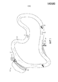
ФИГ. 1 представляет собой вид в перспективе аттракциона медленная река, содержащего устройство раздачи плавучих средств в соответствии с представленными технологиями;FIG. 1 is a perspective view of a slow river attraction comprising a floating dispenser in accordance with the present technologies;
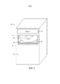
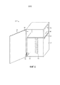
ФИГ. 2 представляет собой вид в перспективе устройства раздачи плавучих средств в соответствии с представленными технологиями;FIG. 2 is a perspective view of a floating dispensing device in accordance with the present technologies;
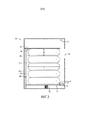
ФИГ. 3 представляет собой вид в поперечном разрезе устройства раздачи плавучих средств фиг. 2;FIG. 3 is a cross-sectional view of the floating dispenser of FIG. 2;
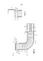
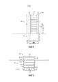
ФИГ. 4 представляет собой вид в поперечном разрезе устройства раздачи плавучих средств, содержащего горизонтальный выталкиватель в соответствии с представленными технологиями;FIG. 4 is a cross-sectional view of a floating dispenser comprising a horizontal ejector in accordance with the present technologies;
ФИГ. 5 представляет собой подробный вид горизонтального выталкивателя фиг. 4;FIG. 5 is a detailed view of the horizontal ejector of FIG. four;
ФИГ. 6 представляет собой вид в перспективе устройства раздачи плавучих средств, содержащего загрузочную или технологическую дверь в соответствии с представленными технологиями;FIG. 6 is a perspective view of a floating dispensing device comprising a loading or processing door in accordance with the present technologies;
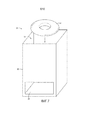
ФИГ. 7 представляет собой вид в перспективе устройства раздачи плавучих средств с верхней загрузкой в соответствии с представленными технологиями;FIG. 7 is a perspective view of a top loading floating dispensing device in accordance with the present technologies;
ФИГ. 8 представляет собой вид сбоку устройства раздачи плавучих средств с верхней загрузкой, содержащего подземную часть в соответствии с представленными технологиями;FIG. 8 is a side view of a top loading floating dispenser comprising an underground part in accordance with the present technologies;
ФИГ. 9 представляет собой вид в поперечном разрезе частично погруженного устройства раздачи плавучих средств в соответствии с представленными технологиями;FIG. 9 is a cross-sectional view of a partially submerged floating dispenser in accordance with the present technologies;
ФИГ. 10 представляет собой вид в перспективе частично погруженного устройства раздачи плавучих средств, содержащего удерживающее устройство в соответствии с представленными технологиями;FIG. 10 is a perspective view of a partially submerged floating dispenser comprising a holding device in accordance with the present technologies;
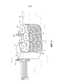
ФИГ. 11 представляет собой вид сверху частично погруженного управляемого течением или потоком устройства раздачи плавучих средств, содержащего удерживающее устройство в соответствии с представленными технологиями; аFIG. 11 is a plan view of a partially submerged flow or distribution device for distributing a floating device comprising a holding device in accordance with the present technologies; but
ФИГ. 12 представляет собой блок-схему устройства раздачи плавучих средств, содержащего контроллер в соответствии с представленными технологиями.FIG. 12 is a block diagram of a floating dispensing apparatus comprising a controller in accordance with the present technologies.
ПОДРОБНОЕ ОПИСАНИЕDETAILED DESCRIPTION
Настоящее раскрытие относится к устройствам раздачи плавучих средств для аттракционов аквапарков. В данном случае предоставлены устройства раздачи, которые обеспечивают упорядоченное содержание и распределение плавучих средств водного аттракциона, таких как водные тюбинги. В некоторых вариантах осуществления устройствами раздачи может вручную управлять пассажир водного аттракциона, который может извлекать плавучее средство через проем в устройстве раздачи. При извлечении плавучего средства из устройства раздачи новое плавучее средство впоследствии перемещается в положение для выдачи следующему пассажиру. Устройства раздачи могут располагаться рядом с различными местами входа в водный аттракцион, чтобы обеспечить получение пассажирами плавучих средств в местах входа на аттракцион. В дополнение, в некоторых вариантах осуществления устройства раздачи выступают в качестве мест сбора плавучих средств после выхода пассажиров из аттракциона. Несмотря на то, что изображенные варианты осуществления раскрыты в контексте медленной реки и плавучих средств в виде водных тюбингов, необходимо понимать, что устройства раздачи настоящего раскрытия могут использоваться в сочетании с другими типами водных аттракционов и/или плавучих средств.The present disclosure relates to devices for the distribution of floating means for attractions of water parks. In this case, dispensing devices are provided that provide an orderly maintenance and distribution of the watercraft floating craft, such as water tubing. In some embodiments, the dispenser may be manually controlled by a passenger of a water attraction that can retrieve a floating device through an opening in the dispenser. When removing the floating means from the dispenser, the new floating means is subsequently moved to a position for dispensing to the next passenger. Distribution devices can be located next to various places of entry into the water attraction to ensure that passengers receive floating equipment at the entrance to the attraction. In addition, in some embodiments, the dispensing devices act as collection points for the floating equipment after the passengers exit the attraction. Although the illustrated embodiments are disclosed in the context of a slow river and floating means in the form of water tubing, it should be understood that the dispensers of the present disclosure may be used in combination with other types of water attractions and / or floating means.
ФИГ. 1 представляет собой вид в перспективе аттракциона 10 медленная река, который содержит водный контур 12 для использования с плавучими средствами 14. Плавучие средства 14 могут быть выполнены в виде водных тюбингов для одного или более пассажиров или в других вариантах осуществления могут представлять собой плоты, доски и т.д. Водный контур 12 проходит в направлении стрелки 16 и имеет разные места 20 для входа пассажиров, распределенные вокруг водного контура 12. Например, каждое место 20 входа может содержать причал или ступени, которые ведут в воду 22. В рамках изобретения, устройство 24 раздачи плавучих средств может располагаться рядом с одним или более местами 20 входа. Таким образом, посетитель парка, который хочет прокатиться на аттракционе 10 медленная река в качестве пассажира 26, может получить плавучее средство 14 из устройства 24 раздачи перед входом в водный контур 12 через место 20 входа. Кроме того, пассажиры, покидающие аттракцион 10, могут загружать свои плавучие средства 14 назад в устройство 24 раздачи для выдачи другим пассажирам. В других вариантах осуществления пассажиры могут оставлять использованные плавучие средства 14 техническому работнику аттракциона, который впоследствии может тогда загружать плавучие средства 14 в устройства 24 раздачи. Устройства 24 раздачи могут служить в качестве центров сбора и выдачи плавучих средств 14, создавая более упорядоченную обстановку в каждом месте 20 входа.FIG. 1 is a perspective view of attraction 10 a slow river that contains a
ФИГ. 2 представляет собой вид в перспективе примера устройства 24 раздачи плавучих средств. Устройство 24 раздачи содержит корпус 30, который имеет размер и форму для содержания нескольких плавучих средств 14. В некоторых вариантах осуществления корпус 30 может содержать текстовую маркировку 32 или обозначения на наружной поверхности 33 корпуса 30 для предупреждения пассажиров водного аттракциона о цели устройства 24 раздачи. В одном варианте осуществления корпус 30 может быть выполнен с возможностью содержания отметок или признаков, подходящих для темы аттракциона. Например, для водного аттракциона с тематикой джунглей корпус 30 может быть выполнен в форме бегемота или тропического дерева. Корпус 30 образует проем 36, открытый во внутреннюю часть корпуса 30, через который пассажир водного аттракциона может получить доступ и извлечь одно или более плавучих средств 14. В некоторых вариантах осуществления плавучие средства 14 могут содержать ручки 38 для облегчения извлечения. В изображенном варианте осуществления устройство 24 раздачи выполнено с возможностью раздачи плавучих средств 14, уложенных вместе в общем в горизонтальном положении (напр., уложенных так, что их самый длинный размер расположен приблизительно параллельно поверхности земли). Соответственно, ручки 38 могут располагаться на боковой стенке 39 плавучих средств, которая открыта в проеме 36. В некоторых вариантах осуществления плавучее средство 14 может содержать множество ручек 38, распределенных вокруг боковой стенки 39 таким образом, чтобы отдельная ручка 38 была доступна через проем независимо от ориентации вращения плавучего средства 14. В других вариантах осуществления плавучие средства 14 можно раздавать в вертикальном или изогнутом положении.FIG. 2 is a perspective view of an example of a
В одном варианте осуществления корпус 30 исполнен в виде свободно стоящей будки (напр., расположенной в месте 20 подхода к водному контуру, см. ФИГ. 1), а проем 36 может располагаться на корпусе 36 на высоте, доступной для среднего пассажира. В дополнение, проем 36 может иметь размер и форму, приспособленные для извлечения по меньшей мере одного плавучего средства 14. С этой целью, высота, обозначенная d1, и длина, обозначенная d2, проема 36, образованного в корпусе 30, могут быть выбраны на основании размеров плавучего средства 14. В одном варианте осуществления высота d1 и длина d2 могут быть выбраны, чтобы они имели по меньшей мере соответствующие размеры плавучего средства 14 для облегчения извлечения плавучего средства 14. В еще одном варианте осуществления одно или оба из высоты d1 и длины d2 могут быть выбраны, чтобы они были немного меньше чем соответствующие размеры плавучего средства 14. Таким образом, плавучее средство 14 удерживается внутри проема 36 корпусом в готовой к раздаче конфигурации, а немного меньший размер проема 36 предотвращает выскальзывание плавучего средства 14 перед раздачей. Однако, по причине того, что плавучее средство 14 может быть образовано из сжимаемого материала, пассажир может сжать плавучее средство 14, чтобы позволить плавучему средству 14 пройти через немного меньший проем 36.In one embodiment, the
Несмотря на то, что изображенный вариант осуществления показывает устройство 24 раздачи, выполненное с возможностью выдачи через проем 36 одного плавучего средства 14, в других вариантах осуществления через проем 36 одновременно можно выдавать два, три или более плавучих средств 14. Например, корпус 30 и проем 36 могут иметь размер и форму, обеспечивающие расположение нескольких плавучих средств 14 в расположенных рядом штабелях, посредством чего в каждом соседнем штабеле через проем 36 доступно верхнее плавучее средство 14. Например, измерение d2 длины может быть относительно больше (напр., в 2-3 раза длиннее), тогда как измерение d1 высоты может быть неизменным относительно варианта осуществления с размером для выдачи одного плавучего средства 14. В еще одном варианте осуществления проем 36 может иметь размер и форму, обеспечивающие одновременное извлечение нескольких плавучих средств 14, уложенных стопкой, верхняя часть к дну. Например, измерение d1 высоты может быть относительно больше (напр., в 2-3 раза длиннее), тогда как измерение d2 длины может быть неизменным относительно варианта осуществления с размером для выдачи одного плавучего средства 14. В таких вариантах осуществления устройство 24 раздачи может обслуживать нескольких пассажиров параллельно, что может привести к повышенной пропускной способности на аттракцион.Although the illustrated embodiment shows a dispensing
ФИГ. 3 представляет собой вид в поперечном разрезе устройства 24 раздачи фиг. 2, показывающий внутреннее пространство 44 корпуса 30. Внутреннее пространство 44 и проем выполнены с возможностью приспосабливания к высоте d3 и диаметру d4 плавучих средств 14 (или другого размера в зависимости от конфигурации). Проем 36 обеспечивает доступ к внутреннему пространству 44, внутри которого содержится множество плавучих средств 14. Плавучие средства 14 поддерживаются базовым элементом 46, который имеет опорную поверхность 48 в контакте с плавучим средством 14 и противоположную поверхность 50, соединенную с пружиной 52. Когда устройство 24 раздачи заполнено, как в изображенном варианте осуществления, пружина 52 сжата, и базовый элемент 46 прикладывает давление на штабель плавучих средств 14 в направлении проема 36 и упорного элемента 54. В некоторых вариантах осуществления упорный элемент 54 расположен в проеме 36 или внутри него таким образом, что самое верхнее плавучее средство 14a в штабеле упирается в поверхность 56 упорного элемента и располагается в проеме 36 для извлечения. Когда плавучее средство 14a извлекают, тогда в проеме 36 располагается плавучее средство 14b за счет расширения пружины 52, которая, в свою очередь, двигает базовый элемент 46 и остальные плавучие средства 14 в направлении проема 36. Несмотря на то, что изображенный вариант осуществления проиллюстрирован с пружиной 52, необходимо понимать, что базовый элемент 46 может приводиться в движение гидравлическим устройством, двигателем, за счет подъемной силы, газовой пружины и т.д.FIG. 3 is a cross-sectional view of the
Базовый элемент 46 может быть выполнен с возможностью расположения внутри проема 36, когда все плавучие средства 14 извлечены, и устройство 24 раздачи опорожнено. В одном варианте осуществления пружина 52 выбрана таким образом, чтобы максимальное расширение пружины располагало базовый элемент 46 на расстоянии от упорного элемента 54, т.е. не в контакте с ним. В еще одном варианте осуществления, когда устройство 24 раздачи опорожнено, базовый элемент 46 прижимается к поверхности 56 упорного элемента 54. В некоторых вариантах осуществления упорный элемент 54 останавливает движение базового элемента 46 в верхнюю часть 57 устройства раздачи. Например, упорный элемент 54 может быть выполнен с возможностью только частичного перекрывания базового элемента 46, оставляя выступ 58 базового элемента 46 относительно упорного элемента 54, который может предотвращать защемление пальцев пассажира между базовым элементом 46 и упорным элементом 54 во время извлечения последнего плавучего средства 14. Выступ 58 также может служить в качестве ручки для облегчения захватывания базового элемента 46 техническим работником или пассажиром для перезагрузки устройства 24 раздачи путем сжатия пружины 52. В других вариантах осуществления устройство 24 раздачи также может быть исполнено без упорного элемента 54. Например, в устройстве раздачи с верхней загрузкой базовый элемент 46 может иметь возможность продолжения в направлении верхней части или крышки устройства 24 раздачи. В одном варианте осуществления для предотвращения наклона базового элемента 46 относительно корпуса 30, который может произойти во время ручной загрузки, корпус 30 также может содержать одну или более внутренних направляющих 59. Базовый элемент 46 может быть выполнен с возможностью скольжения или движения вдоль внутренней направляющей 59 по мере того, как базовый элемент 46 движется внутри корпуса 30.The
Устройства 24 раздачи в рамках изобретения могут располагаться в воде или около нее. В еще одном варианте осуществления устройство 24 раздачи по меньшей мере частично может быть в земле, как показано на фиг. 4. Устройство 24 раздачи содержит подземную часть 61 и надземную часть 62. Такое расположение обеспечивает загрузку и хранение большего количества плавучих средств 14, не влияя на занимаемую площадь аквапарка. Устройство 24 раздачи в рамках изобретения также может содержать горизонтальный выталкиватель 63, который выталкивает самое верхнее плавучее средство из корпуса. Изображенный вариант осуществления находится в закрытой конфигурации, причем дверь 64 устройства раздачи закрывает проем 36. При открывании двери, как показано на фиг. 5, дверь 64 поворачивается вокруг соединительного устройства 65, которое, в свою очередь, толкает горизонтальный исполнительный механизм 66 в направлении плавучего средства 14a для по меньшей мере частичного выталкивания плавучего средства 14a из проема 36 для извлечения пассажиром.
Снова обращаясь к ФИГ. 4, подземная часть 61 также может обеспечивать загрузку на уровне земли. Например, пассажир или технический работник может приводить в действие ручку 67, соединенную с базовым элементом 46, для увеличения натяжения пружины 52 и создания пространства для загрузки дополнительных плавучих средств. Крышка 68 (напр., телескопическая крышка или дверь) может предотвращать доступ к внутреннему пространству 44.Referring again to FIG. 4, the
В некоторых вариантах осуществления устройство 24 раздачи может быть повторно загружено пассажиром или техническим работником аттракциона. Как проиллюстрировано на фиг. 6, внутреннее пространство устройства 24 раздачи может быть доступно через дверь 70, шарнирно соединенную с корпусом 30. При определении, что устройство 24 раздачи опорожнено, например, вследствие того, что опорная поверхность 48 базового элемента 46 открыта, технический работник может получить доступ во внутреннее пространство 44 и загрузить плавучие средства 14. В изображенном варианте осуществления базовый элемент 46 соединен с телескопической или гибкой крышкой 72, которая двигается в сочетании с базовым элементом 46 и которая предотвращает доступ к пружине 52, напр., для защиты плавучих средств 14 от защемления или прокалывания пружиной 52 во время загрузки. Устройство 24 раздачи также может содержать пружинный замок 73, такой как поворотный штифт, который, когда переведен в запертое положение, предотвращает движение базового элемента 46 вверх, удерживая пружину 52 в сжатой конфигурации после того, как базовый элемент 46 был сдвинут вниз для загрузки. Пружина 52 может быть выбрана для сжатия в загруженное положение с силой, которую можно прикладывать вручную.In some embodiments, the
В еще одном варианте осуществления устройство 24 раздачи может быть исполнено без пружины или внутреннего смещающего механизма. Например, устройство 24 раздачи, проиллюстрированное на фиг. 7, производит выдачу через нижний проем 36, который находится ниже, чем загрузочный проход 74. При выдаче нижнего плавучего средства 14 каждое последующее плавучее средство 14 сдвигается вниз в направлении проема 36. Соответственно, вместо или в дополнение к пружине или другим смещающим силам, устройство 24 раздачи может зависеть от силы тяжести. В одном варианте осуществления корпус 30 устройства 24 раздачи может быть изогнут, напр., с конфигурацией в виде тоннеля или желоба для обеспечения верхней загрузки через загрузочный проход 70 даже для относительно невысоких пассажиров.In yet another embodiment, the
ФИГ. 8 представляет собой альтернативный вариант осуществления устройства 24 раздачи, содержащего подземную часть. В проиллюстрированном варианте осуществления устройство 24 раздачи может иметь подземную часть 61 и надземную часть 62. Корпус 30 может быть образован двумя или более разнесенными столбиками (напр., двумя, тремя, четырьмя или более столбиками) таким образом, чтобы вся боковая сторона устройства раздачи была открыта с образованием проема, который может быть меньше чем плавучие средства по меньшей мере в одном измерении (напр., в измерении по ширине) для удержания плавучих средств 14 на месте. Таким образом, посетитель может вытаскивать любое удобно расположенное плавучее средство 14 вдоль всей боковой стороны устройства 24 раздачи без ограничения высотой проема, которая может быть удобной для посетителей разного роста. Кроме того, корпус 30 может иметь открытые боковые стенки с многих сторон, обеспечивая доступ к плавучим средствам 14 с многих сторон устройства 24 раздачи. В одном варианте осуществления корпус 30 образован столбиками, расположенными в четырех углах корпуса 30, образуя соответствующие открытые проемы в боковых стенках. Устройство 24 раздачи может загружаться под действием силы тяжести через верх 72, причем при извлечении каждого отдельного плавучего средства 14 пружина 52 толкает базовый элемент 46 в направлении верхней части 72. Расстояние d1 под землей и расстояние d2 над землей может быть выбрано, чтобы обеспечить требуемую емкость и размер устройства 24 раздачи.FIG. 8 is an alternative embodiment of a
В рамках изобретения в любом из раскрытых вариантов осуществления пружина 52 может иметь усилие пружины, откалиброванное, чтобы обеспечить передвижение базового элемента 46 вверх приблизительно на высоту одного плавучего средства 14 после извлечения из устройства раздачи одного плавучего средства 14. Усилие пружины может определяться материалом и количеством витков пружины 52 и может определять расстояние, на которое продвигается базовый элемент 46.In the framework of the invention, in any of the disclosed embodiments, the
Устройства 24 раздачи в рамках изобретения могут быть выполнены с возможностью исполнения на берегу медленной реки, т.е. вне воды. В еще одном варианте осуществления устройства 24 раздачи могут быть исполнены с расположением по меньшей мере частично в воде 22, как показано на фиг. 9. Кроме того, несмотря на то, что погруженные или частично погруженные устройства 24 раздачи могут быть выполнены с возможностью раздачи плавучих средств 14 с использованием подъемной силы (напр., путем загрузки в воде и обеспечения заплывания плавучего средства 14 в проем 36) и/или усилий пружин, устройство 24 раздачи для помощи в выдаче плавучих средств 14 также может использовать струю течения воды 22. Например, в одном варианте осуществления корпус 30 устройства 24 раздачи по меньшей мере частично расположен в воде 22 так, чтобы проточное отверстие 76 открывалось в воду 22. Течение аттракциона 10 медленная река (см. ФИГ. 1) толкает воду 22 через проточное отверстие 76 и в контакт с базовым элементом 46. Проточное отверстие 76 выполнено с возможностью расположения ниже базового элемента 46 или близко к противоположной поверхности 50. Вода 22 прикладывает к базовому элементу 46 давление вверх с выталкиванием плавучих средств в направлении проема 36. В изображенном варианте осуществления проем 36 может быть исполнен на множестве сторон корпуса 30, обеспечивая многонаправленную раздачу плавучих средств 14. Базовый элемент 46 может быть соединен с корпусом 30 посредством телескопической штанги 78, которая обеспечивает передвижение базового элемента 46 относительно корпуса 30 в результате давления воды. Когда самое верхнее плавучее средство 14a извлекают из устройства 24 раздачи через проем 36, следующее плавучее средство 14b прижимается к верхней части или крышке 79 устройства 24 раздачи базовым элементом 46, который совместно толкает все плавучие средства 14. Положение крышки 79 может быть на удобной высоте грудной клетки пассажира, стоящего в воде 22. В некоторых вариантах осуществления крышка 79 может выступать из воды 22 на заданное расстояние для облегчения легкости осмотра и доступа.
В еще одном варианте осуществления, как показано на фиг. 10, частично погруженное устройство 24 раздачи может обеспечивать по существу совпадающие загрузку и извлечение плавучих средств 14 при относительно небольшом вмешательстве технического работника. Например, корпус 30 может быть выполнен с возможностью иметь открытую заднюю часть 80, т.е. открытую для протекания воды в направлении течения, показанного стрелкой 81, которая соединена с удерживающим элементом 82, таким как сеть, образующим зону 83 хранения, выполненную с возможностью сбора использованных плавучих средств 14 и предотвращения самопроизвольного движения собранных плавучих средств 14 в воде 22. В одном варианте осуществления удерживающий элемент 80 может обеспечивать протекание воды в направлении течения через отверстия 84 или поры. Таким образом, вода 22 проходит внутрь зоны 83 хранения и в направлении проема 36, выталкивая плавучие средства 14 в направлении проема для выдачи. Удерживающий элемент 82 может быть относительно конформным, чтобы размер зоны 83 хранения изменялся по мере того, как течение толкает удерживающий элемент 82. Кроме того, удерживающий элемент 82 может быть образован из упругого материала и смещен в направлении проема 36. Таким образом, удерживающий элемент 82 может расширяться с созданием большей зоны 83 хранения и может дополнительно создавать дополнительное смещение, наряду с протеканием струи воды в направлении проема 36. В еще одном варианте осуществления удерживающий элемент 82 может быть относительно жестким, обеспечивая сквозное протекание воды, но образуя относительно фиксированную зону 83 хранения. Входящий пассажир 26a может извлекать плавучее средство 14a через проем в то время, как выходящий пассажир 26b помещает использованное плавучее средство 14b в зону 83 хранения. По причине того, что зоны извлечения и оставления проиллюстрированного устройства 24 раздачи находятся на расстоянии друг от друга, пассажиры 26 могут загружаться и выгружаться параллельно, что может улучшать пропускную способность аттракциона и заторы на входе. Удерживающий элемент 82 можно снимать с корпуса 80 за счет соединительных приспособлений 86 (напр., крюков, ремней, крепежных приспособлений). Например, если удерживающим элементом 82 является сеть с закрытой нижней поверхностью, при закрытии аттракциона, удерживающий элемент 82 можно извлекать целиком совместно с любыми закрытыми плавучими средствами 14, обеспечивая очистку и/или обслуживание.In yet another embodiment, as shown in FIG. 10, a partially submerged
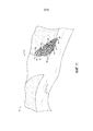
ФИГ. 11 представляет собой схематичную иллюстрацию водного аттракциона 10, содержащего управляемое течением устройство 24 раздачи плавучих средств 14, которое может быть исполнено рядом с зоной входа в воду, напр., с зоной входа с нулевой глубиной. Такое устройство 24 раздачи может быть исполнено без подвижной платформы или другого фиксированного корпусного элемента. Вместо этого, течение 16 толкает любые свободные плавучие средства 14 через вход 90 для тюбингов в зону 91 локализации, образованную стенками 92 или другими ограничивающими элементами (напр., сетью, канатами и т.д.). Плавучие средства 14 захватываются таким образом устройством 24 раздачи, обеспечивая, чтобы на аттракционе 10 не было неиспользуемых плавучих средств 14. Устройство раздачи также содержит выход 94 для тюбингов, который позволяет плавучим средствам 14 выходить в направлении стрелки 96 для использования посетителями, входящими в аттракцион 10. Плавучие средства 14 могут выталкиваться водометами 98, которые выполнены таким образом, чтобы струйное течение выталкивало плавучее средство 14 из входа 90 для тюбингов в направлении выхода 94 для тюбингов. Выход 94 для тюбингов может быть образован, чтобы он был меньше чем плавучее средство 14 по меньшей мере в одном измерении для сохранения внутри зоны локализации плавучих средств 14, теснящихся напротив выхода 94 для тюбингов, и таким образом, чтобы извлечение плавучего средства 14 требовало прикладывания посетителями тянущего усилия (напр., тянущего усилия, которое сжимает плавучее средство 14, обеспечивая выход через выход 94 для тюбингов). Таким образом, выход 94 для тюбингов имеет постоянный поток плавучих средств 14, стоящих в очереди и готовых к выдаче и которые не могут выйти назад на аттракцион 10 без вмешательства посетителей.FIG. 11 is a schematic illustration of a
В некоторых вариантах осуществления различные признаки устройства 24 раздачи могут работать в системе 100 управления, как показано на блок-схеме фиг. 12. Система 100 управления может содержать процессор 102, который может содержать одно или более устройств обработки, и память 104, хранящую команды, выполняемые процессором 102. Память 104 может содержать один или более материальных, энергонезависимых, машиночитаемых носителей. В качестве примера, такой машиночитаемый носитель может содержать RAM, ROM, EPROM, EEPROM, CD-ROM или другое оптическое дисковое запоминающее устройство, магнитное дисковое запоминающее устройство или другие магнитные запоминающие устройства, или любой другой носитель, который может использоваться для выполнения или хранения требуемого программного кода в виде выполняемых машиной команд или структур данных и к которому может иметь доступ процессор 102 или любой компьютер общего назначения или специального назначения или другая машина с процессором. Система 100 управления также может содержать схему 105 связи и/или схему 106 входных и выходных данных для облегчения связи с другими компонентами устройства 24 раздачи и/или с системами управления аквапарка. Кроме того, контроллер 100 может содержать дисплей 108, который предоставляет техническим работникам или пассажирам информацию о статусе устройства 24 раздачи.In some embodiments, various features of the
В одном варианте осуществления дисплей 108 предоставляет сообщение ОПОРОЖНЕНИЯ или ПЕРЕЗАГРУЗКИ в ответ на входной сигнал от датчика, соединенного с корпусом 30, который означает, что все плавучие средства были извлечены из устройства 24 раздачи. Например, такая сенсорная система может содержать светоизлучатель 110, который излучает свет (показанный стрелкой 111) под управлением контроллера 100 в направлении детектора 112. На основании количества зафиксированного света, система 100 управления может определять, опорожнено ли устройство 24 раздачи. Для оценки статуса устройства 24 раздачи также могут быть задействованы другие типы сенсорных систем, такие как датчики близости или датчики положения, соединенные с базовым элементом 46. В дополнение к предоставлению на дисплей 108 сообщения, статус опорожнения также может быть передан в систему управления парка для того, чтобы можно было запланировать перезагрузку.In one embodiment, the display 108 provides an EMPTY or RESET message in response to an input from a sensor connected to the
Система 100 управления также может управлять движением базового элемента 46 посредством механического регулятора 116, соединенного с двигателем 118, который приводит в движение базовый элемент 46 для передвижения вверх или вниз внутри корпуса 30. В дополнение, механический регулятор 116 (который в некоторых вариантах осуществления может быть исполнен отдельно от контроллера двигателя базового элемента) может управлять открыванием и закрыванием двери 64, закрывающей проем 36. Например, механический регулятор 116 также может управлять двигателем, соединенным с дверью 64 и который переводит дверь 64 из закрытого положения в открытое положение. Механический регулятор 116 также может управлять горизонтальным выталкивателем 63. В одном варианте осуществления система 100 управления может принимать входной сигнал от посетителя, напр., посредством устройства 122 на теле человека (браслета, бейджа и т.д.), которое считывается с помощью считывателя 124, который, в свою очередь, передает идентификационную информацию 126 для посетителя в систему управления. Если входной сигнал означает, что посетитель получил разрешение на доступ в водный аттракцион, механический регулятор 116 открывает дверь 64, обеспечивая доступ к плавучим средствам. Если посетитель не получил разрешение на доступ в водный аттракцион, дверь 64 остается в закрытом по умолчанию положении.The
Система 100 управления также может управлять контроллером 130 доставки текучей среды, который активирует доставку моющей жидкости в устройство 24 раздачи для мойки плавучих средств. Контроллер 130 доставки текучей среды соединен с одним или более источниками 132 текучей среды, содержащими моющую жидкость (напр., воду, дезинфицирующее средство) с возможностью передачи текучей среды в один или более портов 134 для впуска текучей среды. В еще одном варианте осуществления плавучие средства можно подвергать воздействию УФ излучения, а устройство 24 раздачи может содержать источник УФ излучения под управлением системы 100 управления. При получении сигнала от системы 100 управления, контроллер 130 доставки текучей среды может открывать протекание текучей среды внутри устройства 24 раздачи, напр., путем открывания клапана для высвобождения текучей среды. Соответственно, контроллер 130 доставки текучей среды может быть соединен с подходящими элементами управления протеканием. В одном варианте осуществления система 100 управления во время протекания текучей среды помещает устройство 24 раздачи в режим мойки, а дверь 64 остается закрытой даже в ответ на действующий входной сигнал посетителя, запрашивающий доступ к плавучим средствам. Когда мойка завершается, устройство 24 раздачи выводят из режима мойки, обеспечивая нормальный доступ посетителей к плавучим средствам. Режим мойки может активироваться по заданному графику или в ответ на входной сигнал оператора. В некоторых вариантах осуществления режим мойки может быть разрешен, только когда устройство 24 раздачи заполнено. Например, технический работник аттракциона может загружать устройство 24 раздачи плавучими средствами, собираемыми по мере того, как пассажиры покидают водный аттракцион, а затем может активировать режим мойки для подготовки плавучих средств для выдачи и повторного использования.The
Несмотря на то, что в настоящем описании были проиллюстрированы и описаны только некоторые признаки настоящего раскрытия, специалисты в данной области встретятся с множеством модификаций и изменений. Кроме того, необходимо понимать, что компоненты различных вариантов осуществления, раскрытых в настоящем описании, могут объединяться или заменяться друг другом. Вследствие этого, должно быть понятно, что приложенная формула изобретения предназначена охватывать все такие модификации и изменения, которые попадают в пределы истинной сущности раскрытия.Although only certain features of the present disclosure have been illustrated and described in the present description, those skilled in the art will encounter many modifications and changes. In addition, it should be understood that the components of the various embodiments disclosed herein can be combined or replaced with each other. Therefore, it should be understood that the appended claims are intended to cover all such modifications and changes that fall within the true spirit of the disclosure.
Claims (35)
Applications Claiming Priority (3)
| Application Number | Priority Date | Filing Date | Title |
|---|---|---|---|
| US14/920,654 | 2015-10-22 | ||
| US14/920,654 US9751021B2 (en) | 2015-10-22 | 2015-10-22 | Water ride flotation device dispenser |
| PCT/US2016/057545 WO2017070116A1 (en) | 2015-10-22 | 2016-10-18 | Water ride flotation device dispenser |
Publications (1)
| Publication Number | Publication Date |
|---|---|
| RU2675103C1 true RU2675103C1 (en) | 2018-12-14 |
Family
ID=57281283
Family Applications (1)
| Application Number | Title | Priority Date | Filing Date |
|---|---|---|---|
| RU2018118587A RU2675103C1 (en) | 2015-10-22 | 2016-10-18 | Device for distributing floating means on water attractions |
Country Status (11)
| Country | Link |
|---|---|
| US (1) | US9751021B2 (en) |
| EP (1) | EP3364823B1 (en) |
| JP (1) | JP6665287B2 (en) |
| KR (1) | KR101895194B1 (en) |
| CN (1) | CN108366678B (en) |
| CA (2) | CA3002734C (en) |
| ES (1) | ES2806727T3 (en) |
| MY (1) | MY186430A (en) |
| RU (1) | RU2675103C1 (en) |
| SG (1) | SG11201802921SA (en) |
| WO (1) | WO2017070116A1 (en) |
Families Citing this family (4)
| Publication number | Priority date | Publication date | Assignee | Title |
|---|---|---|---|---|
| JP6160614B2 (en) | 2012-07-04 | 2017-07-12 | 東京エレクトロン株式会社 | Substrate processing equipment |
| US10099868B1 (en) * | 2017-04-20 | 2018-10-16 | Otto Kierulff Da Costa | Set of water pipes with capsules for heavy cargo and irrigation transportation system |
| US11130068B2 (en) | 2018-11-20 | 2021-09-28 | Universal City Studios Llc | Water amusement ride motion governor |
| US10825196B2 (en) * | 2019-02-15 | 2020-11-03 | Universal City Studios Llc | Object orientation detection system |
Citations (4)
| Publication number | Priority date | Publication date | Assignee | Title |
|---|---|---|---|---|
| US3642170A (en) * | 1970-05-08 | 1972-02-15 | George R Shelley | Combination holddown finger and plate separator for self-leveling plate dispensers |
| US20050095470A1 (en) * | 2003-10-30 | 2005-05-05 | Harding Philip H. | Method and system for dispensing pelletized fuel for use with a fuel cell |
| FR2872013A1 (en) * | 2004-06-29 | 2005-12-30 | Polycaptil Sa | Tray distributor for e.g. school canteen, has tray extraction unit disposed in upper part and that displaces tray in waiting position to top of stack of trays in extraction direction across slot |
| RU2481781C2 (en) * | 2009-04-01 | 2013-05-20 | Стефано ОНЬИССАНТИ | Dispenser of disposable plates for food products and corresponding disposable plate |
Family Cites Families (22)
| Publication number | Priority date | Publication date | Assignee | Title |
|---|---|---|---|---|
| US2406250A (en) * | 1943-04-24 | 1946-08-20 | Justin D Petouhoff | Life raft release |
| US2585872A (en) | 1946-05-16 | 1952-02-12 | Steiner Louis | Magazine structure for dispensing devices |
| US2805430A (en) * | 1953-11-04 | 1957-09-10 | Roscoe H Philbrick | Life preserver storage unit and seat for motor boats |
| US3168964A (en) | 1963-10-04 | 1965-02-09 | Ralph R Davis | Article dispensing device |
| GB1088683A (en) | 1965-06-09 | 1967-10-25 | American Mach & Foundry | Temperature control of a housing containing a dispensing mechanism for stacked articles |
| US4171753A (en) | 1976-12-10 | 1979-10-23 | Bastiaan Vreede | Holder for capsules, pills and similar objects |
| US5853332A (en) * | 1995-08-21 | 1998-12-29 | Briggs; Rick A. | Participatory play structure having discrete play articles |
| US5820471A (en) * | 1989-11-20 | 1998-10-13 | Briggs; Rick A. | Participatory water play system |
| JPH03171282A (en) * | 1989-11-30 | 1991-07-24 | Ooshiyan Rain:Kk | Prepaid coin |
| US5453054A (en) * | 1994-05-20 | 1995-09-26 | Waterworld Products, Inc. | Controllable waterslide weir |
| JP3075501U (en) * | 2000-04-24 | 2001-02-23 | サンコースプリング株式会社 | Push-up dispenser |
| JP2003044980A (en) * | 2001-07-27 | 2003-02-14 | Honda Motor Co Ltd | Vehicle sharing system |
| WO2003099663A2 (en) * | 2002-05-21 | 2003-12-04 | Seaquist Perfect Dispensing Foreign, Inc. | Aerosol dispenser for mixing and dispensing multiple fluid products |
| US8152004B2 (en) * | 2005-05-05 | 2012-04-10 | Dixie Consumer Products Llc | Dispenser for disposable cutlery and components therefor |
| US7727077B2 (en) * | 2005-08-03 | 2010-06-01 | Water Ride Concepts, Inc. | Water amusement park water channel flow system |
| US7758435B2 (en) | 2005-09-02 | 2010-07-20 | Water Ride Concepts, Inc. | Amusement water rides involving interactive user environments |
| US7435028B2 (en) * | 2006-01-12 | 2008-10-14 | Colgate-Palmolive Company | Push-up dispenser |
| JP2009095362A (en) * | 2007-10-12 | 2009-05-07 | Shibaura Jihanki Kk | Fixtures |
| CA2741715C (en) * | 2008-10-27 | 2016-08-02 | Nielsen, Gwen | Interactive manual cup dispenser |
| JP6302621B2 (en) * | 2013-02-07 | 2018-03-28 | 日本たばこ産業株式会社 | Magazine and magazine stack structure |
| DE202014001720U1 (en) * | 2014-02-27 | 2015-03-02 | Gerhard Brugger | donor |
| US9560920B2 (en) * | 2014-04-11 | 2017-02-07 | Dixie Consumer Products Llc | Forward advancing cutlery dispenser |
-
2015
- 2015-10-22 US US14/920,654 patent/US9751021B2/en active Active
-
2016
- 2016-10-18 MY MYPI2018000533A patent/MY186430A/en unknown
- 2016-10-18 WO PCT/US2016/057545 patent/WO2017070116A1/en not_active Ceased
- 2016-10-18 ES ES16794461T patent/ES2806727T3/en active Active
- 2016-10-18 SG SG11201802921SA patent/SG11201802921SA/en unknown
- 2016-10-18 JP JP2018521117A patent/JP6665287B2/en active Active
- 2016-10-18 CA CA3002734A patent/CA3002734C/en active Active
- 2016-10-18 CA CA3044893A patent/CA3044893C/en active Active
- 2016-10-18 CN CN201680075642.5A patent/CN108366678B/en active Active
- 2016-10-18 EP EP16794461.0A patent/EP3364823B1/en active Active
- 2016-10-18 RU RU2018118587A patent/RU2675103C1/en active
- 2016-10-18 KR KR1020187014247A patent/KR101895194B1/en active Active
Patent Citations (4)
| Publication number | Priority date | Publication date | Assignee | Title |
|---|---|---|---|---|
| US3642170A (en) * | 1970-05-08 | 1972-02-15 | George R Shelley | Combination holddown finger and plate separator for self-leveling plate dispensers |
| US20050095470A1 (en) * | 2003-10-30 | 2005-05-05 | Harding Philip H. | Method and system for dispensing pelletized fuel for use with a fuel cell |
| FR2872013A1 (en) * | 2004-06-29 | 2005-12-30 | Polycaptil Sa | Tray distributor for e.g. school canteen, has tray extraction unit disposed in upper part and that displaces tray in waiting position to top of stack of trays in extraction direction across slot |
| RU2481781C2 (en) * | 2009-04-01 | 2013-05-20 | Стефано ОНЬИССАНТИ | Dispenser of disposable plates for food products and corresponding disposable plate |
Also Published As
| Publication number | Publication date |
|---|---|
| CA3002734A1 (en) | 2017-04-27 |
| SG11201802921SA (en) | 2018-05-30 |
| JP2019500072A (en) | 2019-01-10 |
| CA3044893C (en) | 2021-01-05 |
| CA3002734C (en) | 2019-07-16 |
| KR101895194B1 (en) | 2018-09-04 |
| ES2806727T3 (en) | 2021-02-18 |
| KR20180064538A (en) | 2018-06-14 |
| CN108366678B (en) | 2020-05-08 |
| MY186430A (en) | 2021-07-22 |
| EP3364823A1 (en) | 2018-08-29 |
| CN108366678A (en) | 2018-08-03 |
| EP3364823B1 (en) | 2020-04-29 |
| US20170113149A1 (en) | 2017-04-27 |
| HK1258912A1 (en) | 2019-11-22 |
| CA3044893A1 (en) | 2017-04-27 |
| WO2017070116A1 (en) | 2017-04-27 |
| US9751021B2 (en) | 2017-09-05 |
| JP6665287B2 (en) | 2020-03-13 |
Similar Documents
| Publication | Publication Date | Title |
|---|---|---|
| RU2675103C1 (en) | Device for distributing floating means on water attractions | |
| ES2632773T3 (en) | Card shuffler | |
| ES2702959T3 (en) | Card deck decks that include storage compartments for multiple cards and related methods | |
| ES2950791T3 (en) | Pusher type arcade machine | |
| CN109559434B (en) | Automatic lunch box machine | |
| US3757813A (en) | Apparatus for transportation and segregated emptying of vessels containing fluids of different density | |
| CN109276890B (en) | Slide entrance system | |
| EP3281908A1 (en) | Pyramidal self-service drink dispenser | |
| HK1258912B (en) | Water ride flotation device dispenser | |
| US9552685B1 (en) | Automatic ball blower | |
| US3446134A (en) | Film developing apparatus | |
| CN109598849B (en) | Automatic lunch box machine | |
| JP6354988B2 (en) | Medal stacking device | |
| US2670565A (en) | Trot line receiver and dispenser | |
| US1324415A (en) | Vending-machine | |
| KR20110106614A (en) | Cup ejector | |
| ES2627740B1 (en) | Butane bottle unassisted vending machine | |
| US2133525A (en) | Vending machine | |
| US754090A (en) | Automatic photographic apparatus. | |
| US367551A (en) | Automatic vending apparatus foe cigars | |
| US1299218A (en) | Ball-rack. | |
| US511285A (en) | Coin operated lung tester | |
| CN116173486A (en) | A method and device for randomly extracting game cards | |
| AU637159B2 (en) | Apparatus for the separation of fluids | |
| CN119827232A (en) | Layered water ecological sampling detection equipment for lakes and reservoirs |