RU8024U1 - LOCK CYLINDER - Google Patents
LOCK CYLINDER Download PDFInfo
- Publication number
- RU8024U1 RU8024U1 RU97107299/20U RU97107299U RU8024U1 RU 8024 U1 RU8024 U1 RU 8024U1 RU 97107299/20 U RU97107299/20 U RU 97107299/20U RU 97107299 U RU97107299 U RU 97107299U RU 8024 U1 RU8024 U1 RU 8024U1
- Authority
- RU
- Russia
- Prior art keywords
- pins
- code
- cylinder
- spring
- loaded
- Prior art date
Links
- 238000010586 diagram Methods 0.000 description 1
- 238000005516 engineering process Methods 0.000 description 1
- 239000000203 mixture Substances 0.000 description 1
- 230000003534 oscillatory effect Effects 0.000 description 1
- 230000035515 penetration Effects 0.000 description 1
- 230000008092 positive effect Effects 0.000 description 1
- 239000000523 sample Substances 0.000 description 1
Landscapes
- Lock And Its Accessories (AREA)
Abstract
Цилиндровое устройство для замка, содержащее корпус с радиально расположенными в ряд подпружиненными штифтами, цилиндр,несущий кодовые штифты, взаимодействующие с соответствующими подпружиненными штифтами, ключ, имеющий кодовую линейку вырезов и поводок, соединенный с подпружиненным ригелем замка, отличающееся тем, что между стенками корпуса и цилиндром введена вне зоны его штифтов втулка со своими подпружиненными от центра к периферии кодовыми штифтами, причем последние располагаются при повороте цилиндра диаметрально напротив дополнительных подпружиненных штифтов корпуса, в зоне расположения втулки на кодовом цилиндре сделан продольный вырез, во втулке установлен стопор поворота цилиндра, а кодовая линейка вырезов ключа увеличена в длину и ее дополнительная часть соответствует кодовым значениям штифтов дополнительной втулки.A cylinder lock device comprising a housing with spring-loaded pins radially arranged in a row, a cylinder carrying code pins interacting with respective spring-loaded pins, a key having a code line of cutouts and a leash connected to a spring-loaded lock bolt, characterized in that between the walls of the housing and the sleeve is inserted outside the area of its pins by a cylinder with its code pins spring-loaded from the center to the periphery, the latter being located diametrically opposite Additional spring-loaded housing pins, a longitudinal cutout is made in the sleeve location area on the code cylinder, a cylinder rotation stopper is installed in the sleeve, and the code line of key cut-outs is increased in length and its additional part corresponds to the code values of the additional sleeve pins.
Description
ЩШШДРОВОЕ yCIPOECTBO ДШ ЗАМКАSHCHDROVOE yCIPOECTBO LH LOCK
Предполагаемая полезная модель относится к охранным объектам и может быть -йспользовена в запирающих и замковых устройствах сейфов, квартир, гаражей..Известны многочисленные конструкции, так называемых английских замков и ключей к ним (1,2,3,4,5,6), содержащих цилиндровый механизм, имеющий корпус с подпружиненными штифтами и кодированные штифты непосредственно в цилиндре, причем пространственное сочетание этих пар штифтов и определяет форму ключа для отпирания замка.The proposed utility model relates to security objects and can be used in locking and locking devices of safes, apartments, garages .. Numerous designs are known, the so-called English locks and keys to them (1,2,3,4,5,6), containing a cylinder mechanism having a housing with spring-loaded pins and coded pins directly in the cylinder, and the spatial combination of these pairs of pins determines the shape of the key for unlocking the lock.
Такие конструкцм имеют низкую секретность, т.к. позволяют путем отмычек прощупывать через замочную скважину количество, размеры и величину перемещения кодовых штифтов/ располагающихся в исходном состоянии над соответствующими подпруадненными штифтами, либо просто вводить в замочную скважину быстр о твердеющие смеси, принимающие форму ключа.Such designs have low secrecy, because they make it possible by means of master keys to probe through the keyhole the number, sizes and amount of movement of the code pins / located in the initial state above the corresponding sub-prudent pins, or simply enter quickly into the keyhole the hardening mixtures that take the form of a key.
Общим недостатком указанных устройств является то, что канал для ввода ключей остается незавдщенным от несанкционированного проникания отмычки и, прозванивания внутреннего устройства замка.A common disadvantage of these devices is that the channel for entering keys remains unapproved from unauthorized penetration of the master key and ringing of the internal device of the lock.
Наиболее близким по технической, сути к заявляемому устройству является выбранный в качестве прототипа замок (7), содержащий диаметрально расположенные в корпусе две линейки подпружиненных штифтов и кодовый цйлищц) с двумя рядами кодовых штифтов, контактирующих с соответствующими подпружиненными штифтами.. : -.The closest in technical, in essence to the claimed device is the lock (7) selected as a prototype, containing two lines of spring-loaded pins and code pin diametrically located in the housing) with two rows of code pins in contact with the corresponding spring-loaded pins ..: -.
МШОб, В27/04;;. B35/IO;: B37/I2; BI3/04; BI9/IO; BI9/I6; .BI9/I8IShOB, B27 / 04 ;;. B35 / IO ;: B37 / I2; BI3 / 04; BI9 / IO; BI9 / I6; .BI9 / I8
Такое конструктивное исполнение несколько увеличивает степень секретности до определенных пределов за счет увеличения числа пар кодовых и подпружиненных штифтов 0 использования для кодирования обеих сторон ключа.This design somewhat increases the degree of security to certain limits by increasing the number of pairs of code and spring pins 0 use to encode both sides of the key.
Однако данная конструкция прототипа имеет тот же недостаток: незащищенность канала ввода ключа от изучения внутреннего устройства механизма всякого рода приспособлениямй-отмычками.However, this prototype design has the same drawback: the key input channel is insecure from studying the internal structure of the mechanism of any kind of master keys.
Заявленный объект также содержит корпус с рядом подпруадненных штифтов, цилиндр, несущ1зй кодовые штифты, взаимодействующие с соответствующими подпружиненными штифтами и ключ с линейкой вырезов под кодовые штифты.- Однако в заявленный объект дополнительно введена между цилиндром и корпусом вне зоны их штифтов втулка со своими подпружиненными от центра к периферии кодовыми , причем кодовые штифты втулки при повороте циливдра располагаются напротив дополнительных подпружиненных корпуса и под углом к оси расположения известных пар штифтов, в зоне расположения дополнительных штифтов на кодовом щлиндре сделан вырез, во втулке установлен стопор, а кодовая линейка вырезов ключа.увеличена в длину и ее дополнительная часть соответствует кодовым значениям дополнительной втулки.The claimed object also contains a housing with a number of spring-loaded pins, a cylinder, bearing code pins interacting with the corresponding spring pins and a key with a line of cuts for code pins. However, a sleeve with its spring loaded from between the cylinder and the housing outside the area of their pins is additionally inserted the center to the periphery of the code, and the code pins of the sleeve when turning the cylinder are opposite the additional spring-loaded housing and at an angle to the axis of the known pairs of pins Comrade, in the area where additional pins are located on the code cylinder, a cutout is made, a stopper is installed in the sleeve, and the code line of key cutouts is enlarged in length and its additional part corresponds to the code values of the additional sleeve.
Технические преимущества заявленного объекта по сравнению с известными устройствами заключаются в следующем:Technical advantages of the claimed object in comparison with known devices are as follows:
-введение промежуточной втулки со своими кодовыми подпружиненными , взаимодействующими определенным образом с допол- ни тельными подпружиненными штифтами корпуса;-Introduction of the intermediate sleeve with its spring-loaded code, interacting in a certain way with additional spring-loaded housing pins;
-определенное пространственное расположение взаимодействующих пар штифтов, обеспечивающих последовательную разблокировку цилиндр Вдрулка, втулка-корпус ;-Specified spatial arrangement of interacting pairs of pins, providing sequential unlocking cylinder Vdrulka, sleeve-housing;
-изменение конструкции ключа, кодовая линейка вырезов которого увеличена в длину и ее дополнительная часть соответствует кодовым значениям штифтов дополнительной втулки.- changing the design of the key, the cut-out code line of which is increased in length and its additional part corresponds to the code values of the pins of the additional sleeve.
Совокупность указанных технических преимуществ заявленного объекта обеспечивает положительный эф-фект, заключающийся в существенном повышении секретности механизма.The combination of these technical advantages of the claimed object provides a positive effect, which consists in a significant increase in the secrecy of the mechanism.
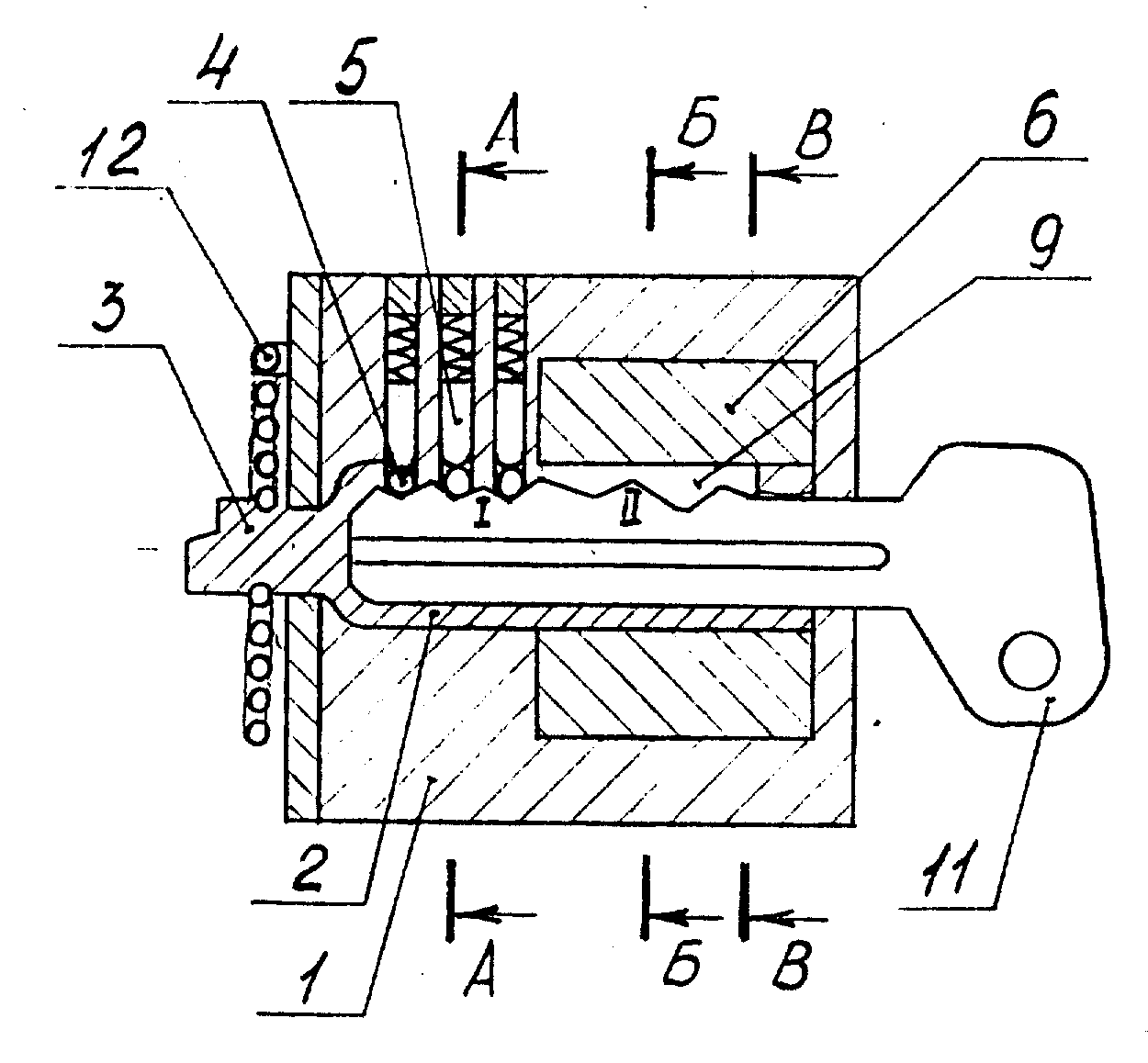
На фяг.1 изображена схема работы цилиндрового устройства для замков на фйг.2 его разрез ло А-А, на фйГ.З по Б-Б, на фиг.4 изображен тот же разрез по Б-Б, но повернут цилиндр на 90°, на фиг.5 дан разрез Б-В, показывающий размещение стопора.Figure 1 shows a diagram of the operation of the cylinder device for locks on figure 2; its section is AA, in figure G.Z along BB, figure 4 shows the same section along BB, but the cylinder is rotated 90 ° , Fig. 5 shows a section BB showing the placement of the stopper.
Щлиндровое устройство для замков содержит корпус I, непосредственно цилиндр 2, связанный с ригелем замка поводком 3. Цилиндр содержит свои кодовые штифты 4, работающие радиально в паре с подпружиненными штифтами 5 корпуса. Между стенкамй корпуса и цилиндром вне зоны расположения щтифтов введена дополнительная втулка 6 со своими кодовыми подпружиненными от центра к периферии штифтами 7, располагаемыми напротив дополнительными подпружиненны|йй штифтвйй корпуса 8, причем последние расположены, например, под углом 90 к оси расположения штифтов 4-5. Б зоне расположения втулки на кодовом цилиндре сделан вырез 9, а во втулке установлен стопор 10, ограничивающий при вращении ключа II поворот цилиндра до оси в-в. Ключ имеет две кодовые линейки вырезов I и П. Бозврат в исходное закрытое положение осуществляется, например, спиральной пружиной 12, закрепленной между поводком и корпусом, или горизонтальной пружиной ригеля замка (не показано на фиг.).The cylinder locking device comprises a housing I, a cylinder 2 directly connected to the lock bolt by a leash 3. The cylinder contains its code pins 4, working radially paired with spring-loaded pins 5 of the housing. Between the walls of the housing and the cylinder, outside the zone of location of the pins, an additional sleeve 6 is inserted with its coded spring-loaded pins 7 located opposite the additional spring-loaded pin of the housing 8, the latter being located, for example, at an angle of 90 to the axis of the location of the pins 4-5 . A cutout 9 is made in the area of the sleeve’s location on the code cylinder, and a stopper 10 is installed in the sleeve, which restricts the rotation of the cylinder to the B-axis during rotation of the key II. The key has two code lines of cut-outs I and P. The return to the initial closed position is carried out, for example, by a spiral spring 12 fixed between the leash and the body, or by a horizontal lock bolt spring (not shown in Fig.).
Цилиндровое устройство для замков работает на отпирание следующим образом.The cylinder lock device operates as unlocked as follows.
После ввода ключа II в скважину цилиндра 2 (см.фиг.1 и фИГ.2) перемещаются кодовые штифты 4, одни торцы которых упираются в кодовые выступы ключа, а другие их торцы устанавливаются в одну линию по Образующей цилиндра с торцами подпружиненных штифтов 5,при этом цилиндр разблокируется и может проворачиваться дальнейшим поворотом ключа относительно корпуса. Это стандартная схема работы типовых английских замков , в которых пассивны кодовые штифты и подпружинены к центру штифты, находящиеся в корпусе.After entering the key II into the bore of the cylinder 2 (see Fig. 1 and FIG. 2), the code pins 4 are moved, one of the ends of which abut against the code ledges of the key, and the other ends of them are installed in a line along the Generator of the cylinder with the ends of the spring pins 5, in this case, the cylinder is unlocked and can be turned by further turning the key relative to the housing. This is the standard scheme of operation of typical English locks in which the code pins are passive and the pins located in the case are spring-loaded to the center.
Б предложенном устройстве (фиг.З) кодовые Подпружиненные от центра штифты 7 первоначально блокируют втулку 6 относительно корпуса I, поэтому она неподвижна. Даже, если злоумышленником подобрана английская кодовая линейка I вырезов ключа, последний может совершать только колебательные движения, ограниченные стопором 10. Значения вырезов, кодовой линейки П заложены величиной кодовых штифтов 7 и толщиной втулки, однако эти штифты располагаются под углом, например, 90 и недоступны для прозванйвания через замочную скважинуIn the proposed device (FIG. 3), the coded spring-loaded pins 7 initially block the sleeve 6 relative to the housing I, therefore, it is stationary. Even if the attacker picked up the English code line I of key cut-outs, the latter can only make oscillatory movements limited by the stopper 10. The values of the cut-outs, code line P are set by the size of the code pins 7 and the thickness of the sleeve, however these pins are located at an angle, for example, 90 and are not available for keying through a keyhole
ЕСЛИ ключ свой, то при дальнейшем его повороте по часовой стрелке (вид со стороны ввода ключа,см.фиг.4 и фиг.5) вдлиндр 2 вырезом 9 упирается по оси в-в в ограничительный стопор 10,при этом вырезы кодовой линейки П ключа II располагаются напротив кодовых штифтов 7 и дополнительных штифтов корпуса 8. Поскольку пруадны штифтов 8 более сильные (жесткие), то противоположные торцы кодовых штифтов 7 будут поджаты к ключу II, а контактные торцовые поверхности штифтов 7 и 8 расположатся по окружности контакта втулки 6 и корпуса I и, таким образом, втулка относительно корпуса разблокируется. При дальнейших поворотах ключа цилиндр 2 будет проворачиваться вместе с втулкой 6 и через поводок 3 воздействовать наригель замка. После целого числа оборотов на отпиранйе замка и открывания дверей устройство возвращается в положение, изображенное на фиг.4. Однако вытащить из сквавдны ключ в этом положении не позволяют штифты 4, смещенные относительно штифтов 5, поэтому ключ следует повернуть в обратную сторону на 90 и вытапить его в положении фиг.2, причем втулка 5 снова заблокируется относительно корпуса, а взведенная пружина 12 возвращает после закрывания дверей поводок 3 с ригелем в исходное положение.IF you have your own key, then further turning it clockwise (view from the side of the key input, see Fig. 4 and Fig. 5), the cylinder 2 cuts out 9 along the b-axis along the stopper 10, while the cut-outs of the code line P of the key II are located opposite the code pins 7 and additional pins of the housing 8. Since the prudent pins 8 are stronger (rigid), then the opposite ends of the code pins 7 will be pressed against the key II, and the contact end surfaces of the pins 7 and 8 will be located around the contact circumference of the sleeve 6 and housing I and thus the sleeve relates It is completely unlocked. With further turns of the key, cylinder 2 will rotate together with the sleeve 6 and, through the leash 3, act on the lock deadlock. After an integer number of revolutions on unlocking the lock and opening the doors, the device returns to the position shown in FIG. 4. However, the pins 4, displaced relative to the pins 5, do not allow the key to be pulled out of the squadron in this position, therefore, the key should be turned back 90 and pulled out in the position of FIG. closing the door leash 3 with the bolt to its original position.
В различных вариантах конструкции данного устройства расположение взаимодействущих пар штифтов 4-5 и 7-8 может быть .под углом отличным от 90°, также как и конструктивное расположение элементов. В частности число пар штифтов может быть увеличено и кодовые вырезы могут быть нанесены на вторую сторону ключа. Однако эти решения известны и по мнению авторов не подлежит патентованию.In various designs of this device, the location of the interacting pairs of pins 4-5 and 7-8 can be. At an angle other than 90 °, as well as the structural arrangement of the elements. In particular, the number of pairs of pins can be increased and code cutouts can be applied to the second side of the key. However, these decisions are known and, according to the authors, are not subject to patenting.
Принципиальное предлагаемого решения от известных подобных устройств заключается в отсутствии возможнрсти вору-злоумышленнйку прощупывать отмычкамивнутреннее устройство механизма, расположение и величину перемещения кодовых штифтов 7. Действительно, прозвонив отмычками при стандартном подходе к типовому английскому замку кодовые штифты 4, и изготовив часть I ключа II, злоумышленник имеет возможность повернуть цилиндр 2 только в пределах 90°, причем втулка 6 не разблокируется. Одновременно злоумышленник сам себе этим ключом как бы затыкает скважину для исследования штифтов 7, смещенных в пространстве.The principle of the proposed solution from known similar devices is the lack of the ability for a thief-malefactor to pick out the internal device of the mechanism, the location and amount of movement of the code pins 7. With a master key, in case of a standard approach to a typical English lock, the code pins 4, and having made part I of key II, the attacker has the ability to turn the cylinder 2 only within 90 °, and the sleeve 6 is not unlocked. At the same time, the attacker shuts the well for himself with this key to examine the pins 7, which are displaced in space.
Указанные ваше конструктивные отличия позволяют создать новый класс замков повышенной секретности.Indicated your design differences allow you to create a new class of locks of high security.
. Применение данного мехашзма существенно повышает секретность (надежность) замков и запорных устройств без каких-либо дополнительных затрат и сложных технологий.. The use of this mechashism significantly increases the secrecy (reliability) of locks and locking devices without any additional costs and complex technologies.
Источники информации, принятые во внимание при составлении заявки:Sources of information taken into account when preparing the application:
1.Описание изобретения к авторскому свидетельству СССР f 224333, , 13/04 (аналог).1. Description of the invention to the USSR copyright certificate f 224333,, 13/04 (analogue).
2.Описание изобретения к авторскому свидетельству СССР 267371, ШДЕ05В, 19/16 (аналог).2. Description of the invention to the copyright certificate of the USSR 267371, SHDE05V, 19/16 (analogue).
3.Описание изобретения к авторскому свидетельству СССР J 316831, МШЕ05В, 19/10 (аналог).3. Description of the invention to the USSR copyright certificate J 316831, МШЕ05В, 19/10 (analogue).
4 Описание изобретения к авторскому свидетельству СССР № 430219, ШдаОбв, 19/18 (аналог).4 Description of the invention to the USSR copyright certificate No. 430219, ShdaObv, 19/18 (analogue).
5.Описание изобретения к авторскому свидетельству СССР № 1.684.447, 1 ШЕ05в, 35/10 (аналог).5. Description of the invention to the USSR copyright certificate No. 1.684.447, 1 ШЕ05в, 35/10 (analogue).
6.Патент США t 4.069.694 (аналог).6. US patent t 4.069.694 (analogue).
7.Замок врезной с фиксатором, типа ЗВ5МС. испускается заводом Сельмаш, г.Киров-14, паспорт БШЯ.332.583.006 ТУ, артикул: C3-I2437 (прототип).7. Mortise lock with lock, type ZV5MS. It is emitted by the Selmash plant, Kirov-14, passport BShA.332.583.006 TU, article: C3-I2437 (prototype).
Claims (1)
Priority Applications (1)
| Application Number | Priority Date | Filing Date | Title |
|---|---|---|---|
| RU97107299/20U RU8024U1 (en) | 1997-05-06 | 1997-05-06 | LOCK CYLINDER |
Applications Claiming Priority (1)
| Application Number | Priority Date | Filing Date | Title |
|---|---|---|---|
| RU97107299/20U RU8024U1 (en) | 1997-05-06 | 1997-05-06 | LOCK CYLINDER |
Publications (1)
| Publication Number | Publication Date |
|---|---|
| RU8024U1 true RU8024U1 (en) | 1998-10-16 |
Family
ID=48269911
Family Applications (1)
| Application Number | Title | Priority Date | Filing Date |
|---|---|---|---|
| RU97107299/20U RU8024U1 (en) | 1997-05-06 | 1997-05-06 | LOCK CYLINDER |
Country Status (1)
| Country | Link |
|---|---|
| RU (1) | RU8024U1 (en) |
Cited By (1)
| Publication number | Priority date | Publication date | Assignee | Title |
|---|---|---|---|---|
| RU2843124C1 (en) * | 2024-05-02 | 2025-07-07 | Максим Николаевич Филиппов | Cylinder locking mechanism and key therefor |
-
1997
- 1997-05-06 RU RU97107299/20U patent/RU8024U1/en active
Cited By (1)
| Publication number | Priority date | Publication date | Assignee | Title |
|---|---|---|---|---|
| RU2843124C1 (en) * | 2024-05-02 | 2025-07-07 | Максим Николаевич Филиппов | Cylinder locking mechanism and key therefor |
Similar Documents
| Publication | Publication Date | Title |
|---|---|---|
| CA2276259A1 (en) | Electronic lock in cylinder of standard lock | |
| MD20040284A (en) | Lock protected from unlocking with a picklock | |
| SE8801170D0 (en) | Door locks | |
| RU8024U1 (en) | LOCK CYLINDER | |
| US4732024A (en) | Lock with security cylinder and extended key | |
| ES2018574B3 (en) | INTERLOCK IN A ROTATING CYLINDER LATCH | |
| WO2003091518A8 (en) | A combination lock | |
| RU2098583C1 (en) | Lock closing mechanism | |
| US3726555A (en) | Door lock | |
| RU2094583C1 (en) | Padlock without shackle | |
| RU8023U1 (en) | LOCK CYLINDER DEVICE | |
| RU2124616C1 (en) | Cylindrical mechanism for lock | |
| ATE126312T1 (en) | SECURITY LOCK FOR A FRONT DOOR OR THE LIKE. | |
| GB2075108A (en) | Cylinder lock and key | |
| US3505837A (en) | Padlock picking guard and driver spacer | |
| RU2124101C1 (en) | High-secrecy cylinder mechanism for locking devices | |
| RU2019660C1 (en) | Electromechanical lock | |
| SU1730412A1 (en) | Padlock | |
| RU2112126C1 (en) | Special lock for reinforced door wings | |
| RU2024720C1 (en) | Handcuffs | |
| RU15115U1 (en) | THE PADLOCK | |
| RU2148139C1 (en) | Cylindrical mechanism of lock secrecy | |
| RU2260101C2 (en) | Code lock-type interlocking device | |
| RU2124102C1 (en) | Cylindrical mechanism of higher secrecy for locking devices | |
| RU2676164C1 (en) | Magnetomechanical lock |