TWI802412B - Containers and container assemblies - Google Patents
Containers and container assemblies Download PDFInfo
- Publication number
- TWI802412B TWI802412B TW111118161A TW111118161A TWI802412B TW I802412 B TWI802412 B TW I802412B TW 111118161 A TW111118161 A TW 111118161A TW 111118161 A TW111118161 A TW 111118161A TW I802412 B TWI802412 B TW I802412B
- Authority
- TW
- Taiwan
- Prior art keywords
- container
- aforementioned
- liquid
- body portion
- recesses
- Prior art date
Links
- 230000000712 assembly Effects 0.000 title description 2
- 238000000429 assembly Methods 0.000 title description 2
- 239000007788 liquid Substances 0.000 claims abstract description 85
- 210000000078 claw Anatomy 0.000 claims abstract description 17
- 230000002093 peripheral effect Effects 0.000 claims description 19
- 229920005989 resin Polymers 0.000 description 26
- 239000011347 resin Substances 0.000 description 26
- 239000010410 layer Substances 0.000 description 18
- 230000003749 cleanliness Effects 0.000 description 17
- 230000000052 comparative effect Effects 0.000 description 16
- 239000000463 material Substances 0.000 description 14
- 239000002245 particle Substances 0.000 description 14
- -1 polyethylene Polymers 0.000 description 13
- 229920005992 thermoplastic resin Polymers 0.000 description 10
- 238000004519 manufacturing process Methods 0.000 description 9
- 229920002120 photoresistant polymer Polymers 0.000 description 9
- 239000000243 solution Substances 0.000 description 8
- 239000004698 Polyethylene Substances 0.000 description 7
- 238000000071 blow moulding Methods 0.000 description 7
- 229920000573 polyethylene Polymers 0.000 description 7
- 239000004065 semiconductor Substances 0.000 description 7
- XEKOWRVHYACXOJ-UHFFFAOYSA-N Ethyl acetate Chemical compound CCOC(C)=O XEKOWRVHYACXOJ-UHFFFAOYSA-N 0.000 description 6
- 229920001903 high density polyethylene Polymers 0.000 description 6
- 239000004700 high-density polyethylene Substances 0.000 description 6
- 239000012535 impurity Substances 0.000 description 6
- 239000011342 resin composition Substances 0.000 description 6
- 239000000126 substance Substances 0.000 description 6
- LYCAIKOWRPUZTN-UHFFFAOYSA-N Ethylene glycol Chemical compound OCCO LYCAIKOWRPUZTN-UHFFFAOYSA-N 0.000 description 5
- 239000003963 antioxidant agent Substances 0.000 description 5
- 230000003078 antioxidant effect Effects 0.000 description 5
- 238000005259 measurement Methods 0.000 description 5
- 239000000049 pigment Substances 0.000 description 5
- 235000013305 food Nutrition 0.000 description 4
- 238000007689 inspection Methods 0.000 description 4
- 239000004973 liquid crystal related substance Substances 0.000 description 4
- 239000012860 organic pigment Substances 0.000 description 4
- 229920000642 polymer Polymers 0.000 description 4
- 229920000098 polyolefin Polymers 0.000 description 4
- 239000008399 tap water Substances 0.000 description 4
- 235000020679 tap water Nutrition 0.000 description 4
- 239000004711 α-olefin Substances 0.000 description 4
- CSCPPACGZOOCGX-UHFFFAOYSA-N Acetone Chemical compound CC(C)=O CSCPPACGZOOCGX-UHFFFAOYSA-N 0.000 description 3
- LFQSCWFLJHTTHZ-UHFFFAOYSA-N Ethanol Chemical compound CCO LFQSCWFLJHTTHZ-UHFFFAOYSA-N 0.000 description 3
- VGGSQFUCUMXWEO-UHFFFAOYSA-N Ethene Chemical compound C=C VGGSQFUCUMXWEO-UHFFFAOYSA-N 0.000 description 3
- 239000005977 Ethylene Substances 0.000 description 3
- OKKJLVBELUTLKV-UHFFFAOYSA-N Methanol Chemical compound OC OKKJLVBELUTLKV-UHFFFAOYSA-N 0.000 description 3
- ZMXDDKWLCZADIW-UHFFFAOYSA-N N,N-Dimethylformamide Chemical compound CN(C)C=O ZMXDDKWLCZADIW-UHFFFAOYSA-N 0.000 description 3
- 239000004743 Polypropylene Substances 0.000 description 3
- YXFVVABEGXRONW-UHFFFAOYSA-N Toluene Chemical compound CC1=CC=CC=C1 YXFVVABEGXRONW-UHFFFAOYSA-N 0.000 description 3
- 150000001336 alkenes Chemical class 0.000 description 3
- 229920001577 copolymer Polymers 0.000 description 3
- 239000002270 dispersing agent Substances 0.000 description 3
- 239000010419 fine particle Substances 0.000 description 3
- 239000001023 inorganic pigment Substances 0.000 description 3
- 229920000092 linear low density polyethylene Polymers 0.000 description 3
- 239000004707 linear low-density polyethylene Substances 0.000 description 3
- 229920001155 polypropylene Polymers 0.000 description 3
- 238000003825 pressing Methods 0.000 description 3
- 239000002356 single layer Substances 0.000 description 3
- 239000003381 stabilizer Substances 0.000 description 3
- VXNZUUAINFGPBY-UHFFFAOYSA-N 1-Butene Chemical compound CCC=C VXNZUUAINFGPBY-UHFFFAOYSA-N 0.000 description 2
- LIKMAJRDDDTEIG-UHFFFAOYSA-N 1-hexene Chemical compound CCCCC=C LIKMAJRDDDTEIG-UHFFFAOYSA-N 0.000 description 2
- WSSSPWUEQFSQQG-UHFFFAOYSA-N 4-methyl-1-pentene Chemical compound CC(C)CC=C WSSSPWUEQFSQQG-UHFFFAOYSA-N 0.000 description 2
- 229920000089 Cyclic olefin copolymer Polymers 0.000 description 2
- 229920000219 Ethylene vinyl alcohol Polymers 0.000 description 2
- KFZMGEQAYNKOFK-UHFFFAOYSA-N Isopropanol Chemical compound CC(C)O KFZMGEQAYNKOFK-UHFFFAOYSA-N 0.000 description 2
- 239000004952 Polyamide Substances 0.000 description 2
- 239000003795 chemical substances by application Substances 0.000 description 2
- 230000007423 decrease Effects 0.000 description 2
- 230000006866 deterioration Effects 0.000 description 2
- 238000010101 extrusion blow moulding Methods 0.000 description 2
- 238000005227 gel permeation chromatography Methods 0.000 description 2
- 238000010102 injection blow moulding Methods 0.000 description 2
- 238000001746 injection moulding Methods 0.000 description 2
- ZXEKIIBDNHEJCQ-UHFFFAOYSA-N isobutanol Chemical compound CC(C)CO ZXEKIIBDNHEJCQ-UHFFFAOYSA-N 0.000 description 2
- 239000000155 melt Substances 0.000 description 2
- 238000000034 method Methods 0.000 description 2
- 239000011859 microparticle Substances 0.000 description 2
- 230000003472 neutralizing effect Effects 0.000 description 2
- JRZJOMJEPLMPRA-UHFFFAOYSA-N olefin Natural products CCCCCCCC=C JRZJOMJEPLMPRA-UHFFFAOYSA-N 0.000 description 2
- 229920002647 polyamide Polymers 0.000 description 2
- 229920000728 polyester Polymers 0.000 description 2
- 239000002994 raw material Substances 0.000 description 2
- 239000002904 solvent Substances 0.000 description 2
- 238000003860 storage Methods 0.000 description 2
- 229910021642 ultra pure water Inorganic materials 0.000 description 2
- 239000012498 ultrapure water Substances 0.000 description 2
- CCTFMNIEFHGTDU-UHFFFAOYSA-N 3-methoxypropyl acetate Chemical compound COCCCOC(C)=O CCTFMNIEFHGTDU-UHFFFAOYSA-N 0.000 description 1
- QTBSBXVTEAMEQO-UHFFFAOYSA-M Acetate Chemical compound CC([O-])=O QTBSBXVTEAMEQO-UHFFFAOYSA-M 0.000 description 1
- 239000004677 Nylon Substances 0.000 description 1
- 239000004642 Polyimide Substances 0.000 description 1
- 239000004734 Polyphenylene sulfide Substances 0.000 description 1
- 239000004793 Polystyrene Substances 0.000 description 1
- 239000004372 Polyvinyl alcohol Substances 0.000 description 1
- 229920002125 Sokalan® Polymers 0.000 description 1
- GWEVSGVZZGPLCZ-UHFFFAOYSA-N Titan oxide Chemical compound O=[Ti]=O GWEVSGVZZGPLCZ-UHFFFAOYSA-N 0.000 description 1
- 239000006096 absorbing agent Substances 0.000 description 1
- 239000004840 adhesive resin Substances 0.000 description 1
- 229920006223 adhesive resin Polymers 0.000 description 1
- 230000004888 barrier function Effects 0.000 description 1
- 238000005452 bending Methods 0.000 description 1
- 230000015572 biosynthetic process Effects 0.000 description 1
- 125000000484 butyl group Chemical group [H]C([*])([H])C([H])([H])C([H])([H])C([H])([H])[H] 0.000 description 1
- 239000006229 carbon black Substances 0.000 description 1
- 238000004140 cleaning Methods 0.000 description 1
- 125000004122 cyclic group Chemical group 0.000 description 1
- 239000000645 desinfectant Substances 0.000 description 1
- 239000003599 detergent Substances 0.000 description 1
- 230000002542 deteriorative effect Effects 0.000 description 1
- 238000000502 dialysis Methods 0.000 description 1
- 238000007599 discharging Methods 0.000 description 1
- 239000003814 drug Substances 0.000 description 1
- 230000000694 effects Effects 0.000 description 1
- 230000007613 environmental effect Effects 0.000 description 1
- 239000012530 fluid Substances 0.000 description 1
- 235000013373 food additive Nutrition 0.000 description 1
- 239000002778 food additive Substances 0.000 description 1
- 238000007429 general method Methods 0.000 description 1
- WGCNASOHLSPBMP-UHFFFAOYSA-N hydroxyacetaldehyde Natural products OCC=O WGCNASOHLSPBMP-UHFFFAOYSA-N 0.000 description 1
- 239000003978 infusion fluid Substances 0.000 description 1
- 239000004611 light stabiliser Substances 0.000 description 1
- 238000004811 liquid chromatography Methods 0.000 description 1
- 229920001684 low density polyethylene Polymers 0.000 description 1
- 239000004702 low-density polyethylene Substances 0.000 description 1
- 229920001179 medium density polyethylene Polymers 0.000 description 1
- 239000004701 medium-density polyethylene Substances 0.000 description 1
- 229910021645 metal ion Inorganic materials 0.000 description 1
- 238000010137 moulding (plastic) Methods 0.000 description 1
- NJPPVKZQTLUDBO-UHFFFAOYSA-N novaluron Chemical compound C1=C(Cl)C(OC(F)(F)C(OC(F)(F)F)F)=CC=C1NC(=O)NC(=O)C1=C(F)C=CC=C1F NJPPVKZQTLUDBO-UHFFFAOYSA-N 0.000 description 1
- 229920001778 nylon Polymers 0.000 description 1
- IEQIEDJGQAUEQZ-UHFFFAOYSA-N phthalocyanine Chemical compound N1C(N=C2C3=CC=CC=C3C(N=C3C4=CC=CC=C4C(=N4)N3)=N2)=C(C=CC=C2)C2=C1N=C1C2=CC=CC=C2C4=N1 IEQIEDJGQAUEQZ-UHFFFAOYSA-N 0.000 description 1
- 229920001483 poly(ethyl methacrylate) polymer Polymers 0.000 description 1
- 229920001713 poly(ethylene-co-vinyl alcohol) Polymers 0.000 description 1
- 229920003229 poly(methyl methacrylate) Polymers 0.000 description 1
- 239000004584 polyacrylic acid Substances 0.000 description 1
- 229920002239 polyacrylonitrile Polymers 0.000 description 1
- 229920001083 polybutene Polymers 0.000 description 1
- 229920001707 polybutylene terephthalate Polymers 0.000 description 1
- 239000004417 polycarbonate Substances 0.000 description 1
- 229920000515 polycarbonate Polymers 0.000 description 1
- 229920000139 polyethylene terephthalate Polymers 0.000 description 1
- 239000005020 polyethylene terephthalate Substances 0.000 description 1
- 229920001721 polyimide Polymers 0.000 description 1
- 229920002959 polymer blend Polymers 0.000 description 1
- 239000004926 polymethyl methacrylate Substances 0.000 description 1
- 229920001955 polyphenylene ether Polymers 0.000 description 1
- 229920000069 polyphenylene sulfide Polymers 0.000 description 1
- 229920002223 polystyrene Polymers 0.000 description 1
- 229920002635 polyurethane Polymers 0.000 description 1
- 239000004814 polyurethane Substances 0.000 description 1
- 239000011118 polyvinyl acetate Substances 0.000 description 1
- 229920002689 polyvinyl acetate Polymers 0.000 description 1
- 229920002451 polyvinyl alcohol Polymers 0.000 description 1
- 239000004800 polyvinyl chloride Substances 0.000 description 1
- 229920000915 polyvinyl chloride Polymers 0.000 description 1
- 238000002360 preparation method Methods 0.000 description 1
- QQONPFPTGQHPMA-UHFFFAOYSA-N propylene Natural products CC=C QQONPFPTGQHPMA-UHFFFAOYSA-N 0.000 description 1
- 125000004805 propylene group Chemical group [H]C([H])([H])C([H])([*:1])C([H])([H])[*:2] 0.000 description 1
- 238000004064 recycling Methods 0.000 description 1
- 238000000926 separation method Methods 0.000 description 1
- 238000009751 slip forming Methods 0.000 description 1
- 235000013599 spices Nutrition 0.000 description 1
- 238000012360 testing method Methods 0.000 description 1
- OGIDPMRJRNCKJF-UHFFFAOYSA-N titanium oxide Inorganic materials [Ti]=O OGIDPMRJRNCKJF-UHFFFAOYSA-N 0.000 description 1
Images


Classifications
-
- B—PERFORMING OPERATIONS; TRANSPORTING
- B65—CONVEYING; PACKING; STORING; HANDLING THIN OR FILAMENTARY MATERIAL
- B65D—CONTAINERS FOR STORAGE OR TRANSPORT OF ARTICLES OR MATERIALS, e.g. BAGS, BARRELS, BOTTLES, BOXES, CANS, CARTONS, CRATES, DRUMS, JARS, TANKS, HOPPERS, FORWARDING CONTAINERS; ACCESSORIES, CLOSURES, OR FITTINGS THEREFOR; PACKAGING ELEMENTS; PACKAGES
- B65D23/00—Details of bottles or jars not otherwise provided for
- B65D23/001—Supporting means fixed to the container
-
- B—PERFORMING OPERATIONS; TRANSPORTING
- B65—CONVEYING; PACKING; STORING; HANDLING THIN OR FILAMENTARY MATERIAL
- B65D—CONTAINERS FOR STORAGE OR TRANSPORT OF ARTICLES OR MATERIALS, e.g. BAGS, BARRELS, BOTTLES, BOXES, CANS, CARTONS, CRATES, DRUMS, JARS, TANKS, HOPPERS, FORWARDING CONTAINERS; ACCESSORIES, CLOSURES, OR FITTINGS THEREFOR; PACKAGING ELEMENTS; PACKAGES
- B65D1/00—Rigid or semi-rigid containers having bodies formed in one piece, e.g. by casting metallic material, by moulding plastics, by blowing vitreous material, by throwing ceramic material, by moulding pulped fibrous material or by deep-drawing operations performed on sheet material
- B65D1/02—Bottles or similar containers with necks or like restricted apertures, designed for pouring contents
-
- B—PERFORMING OPERATIONS; TRANSPORTING
- B65—CONVEYING; PACKING; STORING; HANDLING THIN OR FILAMENTARY MATERIAL
- B65D—CONTAINERS FOR STORAGE OR TRANSPORT OF ARTICLES OR MATERIALS, e.g. BAGS, BARRELS, BOTTLES, BOXES, CANS, CARTONS, CRATES, DRUMS, JARS, TANKS, HOPPERS, FORWARDING CONTAINERS; ACCESSORIES, CLOSURES, OR FITTINGS THEREFOR; PACKAGING ELEMENTS; PACKAGES
- B65D23/00—Details of bottles or jars not otherwise provided for
- B65D23/10—Handles
-
- B—PERFORMING OPERATIONS; TRANSPORTING
- B65—CONVEYING; PACKING; STORING; HANDLING THIN OR FILAMENTARY MATERIAL
- B65D—CONTAINERS FOR STORAGE OR TRANSPORT OF ARTICLES OR MATERIALS, e.g. BAGS, BARRELS, BOTTLES, BOXES, CANS, CARTONS, CRATES, DRUMS, JARS, TANKS, HOPPERS, FORWARDING CONTAINERS; ACCESSORIES, CLOSURES, OR FITTINGS THEREFOR; PACKAGING ELEMENTS; PACKAGES
- B65D25/00—Details of other kinds or types of rigid or semi-rigid containers
- B65D25/20—External fittings
- B65D25/22—External fittings for facilitating lifting or suspending of containers
-
- B—PERFORMING OPERATIONS; TRANSPORTING
- B65—CONVEYING; PACKING; STORING; HANDLING THIN OR FILAMENTARY MATERIAL
- B65D—CONTAINERS FOR STORAGE OR TRANSPORT OF ARTICLES OR MATERIALS, e.g. BAGS, BARRELS, BOTTLES, BOXES, CANS, CARTONS, CRATES, DRUMS, JARS, TANKS, HOPPERS, FORWARDING CONTAINERS; ACCESSORIES, CLOSURES, OR FITTINGS THEREFOR; PACKAGING ELEMENTS; PACKAGES
- B65D25/00—Details of other kinds or types of rigid or semi-rigid containers
- B65D25/20—External fittings
- B65D25/24—External fittings for spacing bases of containers from supporting surfaces, e.g. legs
-
- Y—GENERAL TAGGING OF NEW TECHNOLOGICAL DEVELOPMENTS; GENERAL TAGGING OF CROSS-SECTIONAL TECHNOLOGIES SPANNING OVER SEVERAL SECTIONS OF THE IPC; TECHNICAL SUBJECTS COVERED BY FORMER USPC CROSS-REFERENCE ART COLLECTIONS [XRACs] AND DIGESTS
- Y02—TECHNOLOGIES OR APPLICATIONS FOR MITIGATION OR ADAPTATION AGAINST CLIMATE CHANGE
- Y02W—CLIMATE CHANGE MITIGATION TECHNOLOGIES RELATED TO WASTEWATER TREATMENT OR WASTE MANAGEMENT
- Y02W30/00—Technologies for solid waste management
- Y02W30/50—Reuse, recycling or recovery technologies
- Y02W30/80—Packaging reuse or recycling, e.g. of multilayer packaging
Landscapes
- Engineering & Computer Science (AREA)
- Mechanical Engineering (AREA)
- Ceramic Engineering (AREA)
- Containers Having Bodies Formed In One Piece (AREA)
- Details Of Rigid Or Semi-Rigid Containers (AREA)
- Catching Or Destruction (AREA)
- Filling Of Jars Or Cans And Processes For Cleaning And Sealing Jars (AREA)
Abstract
提供一種就算是在進行使用有高壓氣體之液體之壓送時容器之內壓成為高壓力,也能夠顯著地抑制起因於送液裝置所導致的容器支持具乃至於容器之變形,而能夠進行安定之送液,並且也具有能夠安置在並不具有容器支持具之送液裝置處地來作使用的高泛用性之容器以及容器組合體。 容器(10),係具備有:本體部(12),係成為略圓筒形;和筒口(11),係於本體部(12)之其中一端而開口;和階差部(13),係與本體部(12)之另外一端相連續並且作了縮徑;和圓底部(15),係與階差部(13)相連續並且以從該處而分離的方式來作了膨脹,在階差部(13)處,係被間歇性地形成有複數之凹部(14),該些複數之凹部(14),係於不會與涵蓋本體部(12)、階差部(13)以及圓底部(15)之一連串的分模線相重疊的位置處而凹陷,並且被與用以使容器自立之支持台之爪部作卡合。 Even if the internal pressure of the container becomes a high pressure during the pressure feeding of liquid using high-pressure gas, the deformation of the container holder and even the container caused by the liquid feeding device can be significantly suppressed, and the stability can be achieved. It also has a highly versatile container and container assembly that can be placed at a liquid delivery device that does not have a container holder for use. The container (10) is provided with: a body portion (12), which is slightly cylindrical; and a cylinder mouth (11), which is tied to one end of the body portion (12) to open; and a step portion (13), which is It is continuous with the other end of the body portion (12) and has been reduced in diameter; and the round bottom (15), which is continuous with the step portion (13) and expanded in a manner separated therefrom, is The difference portion (13) is intermittently formed with plural recesses (14), and these plural recesses (14) are not connected with the covering body portion (12), the step portion (13) and the circle. The position where a series of parting lines of the bottom (15) overlap is recessed, and is engaged with the claws of the support platform for making the container stand on its own.
Description
本發明,係有關於用以收容液體之容器、以及包含此容器之容器組合體。The present invention relates to a container for accommodating liquid, and a container assembly including the container.
在半導體製造和液晶顯示器製造中所使用的光阻劑或洗淨劑之類的工業用高純度藥液以及像是食品用材料液一般之液體,係為了不會發生異物之混入或變質,而以高純度的狀態來收容在容器中。此些之液體,係在被收容於容器中的狀態下而被作儲存、搬送,並被安置在送液裝置處而被從容器排出並被作使用。Industrial high-purity chemical liquids such as photoresists and detergents used in semiconductor manufacturing and liquid crystal display manufacturing, and liquids such as food material liquids, are designed to prevent foreign matter from being mixed or deteriorated. It is contained in a container in a state of high purity. These liquids are stored and transported in a state of being accommodated in a container, and are placed in a liquid delivery device to be discharged from the container and used.
在此種容器處之底面,一般而言係以能夠使容器自立的方式而被形成為平坦。作為周知技術,係周知有下述一般之由壓送所致之液體之排出方法,其係將送液管以及氣體供給管插入至容器內,並從氣體供給管而將氣體送入至容器內,再藉由此氣體來提高容器的內壓並將液體送至送液管中,而將液體從容器排出。於此情況,為了壓送高黏度而難以流動的液體,有時會使用有例如100~200kPa一般之高壓氣體。具有平坦之底面的一般所周知之容器,若是起因於高壓氣體而導致容器內之壓力提高,則會有以底面發生膨脹隆起的方式而變形並導致容器傾斜的情形。若是在容器內的液體之殘量變少,則起因於底面之變形或者是容器之傾斜,液體會成為無法到達送液管之前端,而會有無法將被收容在容器內之所有的液體從容器而排出之虞。The bottom surface of such a container is generally formed flat so that the container can stand on its own. As a well-known technique, the following general method of discharging liquid by pressure feeding is known, which is to insert a liquid feeding pipe and a gas supply pipe into the container, and send gas into the container from the gas supply pipe. , and then use this gas to increase the internal pressure of the container and send the liquid to the liquid delivery pipe to discharge the liquid from the container. In this case, in order to pressure-feed liquids with high viscosity and difficulty in flowing, for example, a general high-pressure gas of 100-200kPa is sometimes used. In a well-known container having a flat bottom surface, if the pressure in the container increases due to high-pressure gas, the bottom surface may expand and bulge and deform, causing the container to tilt. If the remaining amount of liquid in the container decreases, the liquid cannot reach the tip of the liquid delivery tube due to the deformation of the bottom surface or the inclination of the container, and all the liquid contained in the container cannot be discharged from the container. And the risk of being expelled.
在專利文獻1中,係記載有將底面設為半球面之容器以及用以使該容器自立之支持台(支撐具)。藉由使在此容器之周壁外面而於周方向連續一周地作了聯繫之凹溝與被設置在支持台之周壁內面處之凸部相卡合,容器與支持台係被作嵌合裝著。藉由使容器之底面成為半球面,上述之起因於高壓氣體所導致的容器內壓力係會均等地施加於底面。此時,由於底面全體係起因於高壓氣體之壓力而朝向下方伸長,因此凹溝係追隨於此伸長而如同渦捲彈簧之伸展一般地來伸長。起因於此,凹溝係會將支撐具之凸部推出,而無法維持與凸部間之卡合。其結果,由於容器係會從支持台而脫落並傾倒,因此,係無法安定地進行壓送。Patent Document 1 describes a container whose bottom surface is a hemispherical surface, and a stand (support) for making the container stand on its own. The container and the support platform are fitted together by engaging the grooves that are continuously connected in the circumferential direction on the outside of the peripheral wall of the container with the protrusions provided on the inner surface of the peripheral wall of the support platform. with. By making the bottom surface of the container a hemispherical surface, the above-mentioned internal pressure in the container caused by the high-pressure gas is evenly applied to the bottom surface. At this time, since the entire bottom surface is elongated downward due to the pressure of the high-pressure gas, the groove follows this elongation and elongates like a spiral spring. Because of this, the concave groove will push out the convex part of the support, and cannot maintain the engagement with the convex part. As a result, since the container falls off the support table and falls down, it cannot be stably pressure-fed.
在專利文獻2中,係記載有一種液體容器,其係具備有具有圓底之容器本體、和於中央處具有貫通部並將此容器本體可自立地作支持之支持台。在容器本體處,係被設置有用以與支持台作卡合之環繞溝。此液體容器,係被安置在送液裝置處而被作使用,該送液裝置,係具備有:台座,係具有與支持台之貫通部相嵌合並與圓底相抵接之突起部;和按壓構件,係按壓容器本體之上端。容器本體由於係被像是在送液裝置處所具備之台座之突起部以及按壓構件一般之容器支持具所包夾,因此,就算是容器本體之內壓提高,環繞溝也不會伸長,容器本體係並不會從支持台而脫落。但是,專利文獻2之液體容器,由於為了藉由高壓氣體來押送容器內之液體,係需要使用具備有像是突起部以及按壓構件一般之容器支持具的送液裝置,因此,能夠安置容器之送液裝置係有所侷限,而缺乏泛用性。 [先前技術文獻] [專利文獻] Patent Document 2 discloses a liquid container including a container body having a round bottom, and a support stand that has a through portion at the center and supports the container body independently. At the container body, there is a surrounding groove for engagement with the support platform. The liquid container is used by being placed in a liquid delivery device, and the liquid delivery device includes: a base having a protrusion that fits into the through portion of the support platform and abuts against the round bottom; and presses The component is to press the upper end of the container body. Since the container body is surrounded by the container support such as the protrusion of the pedestal and the pressing member provided in the liquid delivery device, even if the internal pressure of the container body increases, the surrounding groove will not stretch, and the container itself will The system does not fall off the support stand. However, in the liquid container of Patent Document 2, in order to convey the liquid in the container by high-pressure gas, it is necessary to use a liquid delivery device equipped with a container holder such as a protrusion and a pressing member. Therefore, the container can be placed The liquid delivery device is limited and lacks versatility. [Prior Art Literature] [Patent Document]
[專利文獻1]日本實開昭58-76899號公報 [專利文獻2]日本特開2011-098736號公報 [Patent Document 1] Japanese Publication No. 58-76899 [Patent Document 2] Japanese Unexamined Patent Publication No. 2011-098736
[發明所欲解決的課題][Problems to be Solved by the Invention]
本發明,係為為了解決前述之課題所進行者,其目的,係在於提供一種就算是在進行使用有高壓氣體之液體之壓送時容器之內壓成為高壓力,也能夠在不存在有在送液裝置處所具備之容器支持具的狀態下而顯著地抑制容器之變形,而能夠進行安定之送液,並且也具有能夠安置在並不具有容器支持具之送液裝置處地來作使用的高泛用性之容器以及容器組合體。 [用以解決問題的手段] The present invention is made to solve the above-mentioned problems, and its object is to provide a method that can maintain the internal pressure of the container even if the internal pressure of the container becomes high during the pressure feeding of the liquid using a high-pressure gas. In the state of the container holder provided at the liquid delivery device, the deformation of the container can be significantly suppressed, and stable liquid delivery can be performed, and it can also be installed at a liquid delivery device that does not have a container holder. Containers and container assemblies with high versatility. [means used to solve a problem]
為了達成前述目的所發明之本發明之容器,係收容液體,並被用以壓送前述液體,其特徵為,係具備有:本體部,係成為略圓筒形;和筒口,係於前述本體部之其中一端而開口;和階差部,係與前述本體部之另外一端相連續並且作了縮徑;和圓底部,係與前述階差部相連續並且以從該處而分離的方式來作了膨脹,在前述階差部處,係被間歇性地形成有複數之凹部,該些複數之凹部,係於不會與涵蓋前述本體部、前述階差部以及前述圓底部之一連串的分模線相重疊的位置處而凹陷,並且被與用以使容器自立之支持台之爪部作卡合,前述凹部係成為於前述本體部之周方向而為長的略長圓形,複數之前述凹部之前述周方向上的合計長度,係佔據前述本體部之最外周長度之20~50%。The container of the present invention invented in order to achieve the above-mentioned purpose is to accommodate liquid and be used to pressurize the above-mentioned liquid. It is characterized in that it is equipped with: a main body that is slightly cylindrical; and a mouth that is tied to the above-mentioned body. One end of the portion is opened; and the stepped portion is continuous with the other end of the body portion and is reduced in diameter; and the round bottom is continuous with the aforementioned stepped portion and separated therefrom. After expansion, a plurality of recesses are intermittently formed at the aforementioned step portion, and these plurality of recesses are not separated from a series of parts covering the aforementioned body portion, the aforementioned step portion, and the aforementioned round bottom. The positions where the mold lines overlap are recessed, and are engaged with the claws of the support table for making the container self-supporting. The aforementioned recesses are elongated in the circumferential direction of the aforementioned main body. The total length of the aforementioned concave portion in the aforementioned peripheral direction occupies 20% to 50% of the outermost peripheral length of the aforementioned main body portion.
在容器處,係亦可採用下述之構成:亦即是,前述凹部,係被設置於在前述本體部之中心軸上之角度為從前述分模線而分別分開20~45˚並且包夾著前述分模線而相對稱之位置的4個場所處、或者是被設置於在前述本體部之中心軸上之角度為從前述分模線而分別分開60˚並且包夾著前述分模線而相對稱之位置的6個場所處。At the container, the following configuration can also be adopted: that is, the aforementioned concave portion is arranged on the central axis of the aforementioned body portion at an angle that is separated from the aforementioned parting line by 20-45° and encloses The 4 positions at the symmetrical positions along the parting line, or the angles provided on the central axis of the body part are separated by 60° from the parting line and sandwich the parting line And the 6 places of corresponding position.
本發明之容器組合體,係使上述之任一者之容器的前述本體部,具備有胴體部和在靠近前述筒口處而較前述胴體部更為縮徑之頸部,並使把手嵌合及/或螺合於前述頸部之外面。In the container assembly of the present invention, the aforementioned body portion of any one of the aforementioned containers is equipped with a body portion and a neck portion that is smaller in diameter than the body portion near the mouth of the barrel, and the handle is fitted and /or screwed on the outside of the aforementioned neck.
容器組合體,係具備有:上述之任一者之容器;和支持台,係具備有將前述圓底部作嵌合之開口、以及從該開口之周緣部而延伸出去並與前述凹部作卡合之爪部,並藉由此而使前述容器自立。 [發明之效果] A container assembly comprising: any one of the above containers; and a support platform having an opening for fitting the aforementioned round bottom, and an opening extending from the peripheral edge of the opening to engage with the aforementioned concave portion claws, and thereby make the aforementioned container self-supporting. [Effect of Invention]
若依據本發明之容器以及容器組合體,則就算是在壓送液體時而容器內成為高壓,藉由將用以與支持台之爪部相卡合的凹部在特定之位置處而間歇性地形成,由於係並不會起因於壓力而發生伸長、變形,因此,支持台係並不會從容器而脫落,而能夠安定地進行液體之壓送。According to the container and the container assembly of the present invention, even if the pressure in the container becomes high pressure when the liquid is pumped, the pressure is intermittently increased by placing the concave portion for engaging with the claw portion of the support table at a specific position. Formation, since the system does not elongate or deform due to pressure, the support system does not fall off from the container, and the liquid can be stably fed by pressure.
又,容器以及容器組合體,在進行液體之壓送時由於容器本身係並不會在其之中心軸方向上而伸長,因此,在送液裝置處係並不需要具有用以抑制容器之變形的容器支持具,故而,係能夠對應於各種的送液裝置,而具有豐富的泛用性。In addition, the container and the container assembly do not need to be provided at the liquid delivery device to suppress the deformation of the container since the container itself does not elongate in the direction of its central axis when the liquid is pumped by pressure. Therefore, the system can correspond to various liquid delivery devices, and has rich versatility.
以下,係針對用以實施本發明之形態詳細進行說明,但是,本發明之範圍係並不被限定於此些之形態。Hereinafter, although the form for carrying out this invention is demonstrated in detail, the scope of the present invention is not limited to these forms.
在圖1中,對於本發明之容器10之其中一例作展示。圖1(a),係為容器10之正面圖,圖1(b)係為(a)之A-A線箭頭方向觀察端面圖。容器10,係為收容液體並且最高能夠耐住200kPa之內壓的壓送用之容器。容器10,係具備有:本體部12,係成為筒形;和筒口11,係於身為此本體部之其中一端之上端而開口;和階差部13,係於身為本體部12之另外一端之下端處而相連續;和圓底部15,係以從此階差部13而分離的方式來連續性地延伸並且朝向下方膨脹而成為略半球形。容器10之內部空間係經由筒口11而與外界相通連。此開口與圓底部15之內壁下端係相互對向。In FIG. 1, one example of the
本體部12,係更進而具備有:上端部12a,係開口有筒口11;和頸部12b,係從上端部12a之下端起而延伸;和胴體部12c,係從頸部12b之下端起而更進一步朝向下方延伸。胴體部12c,係朝向頸部12b而逐漸縮徑。又,在上端部12a以及頸部12b之外周面處,係分別突出有公螺紋12a
1、12b
1。
The
容器10係為樹脂製,並藉由直接吹塑成形而被形成。在直接吹塑成形中,首先係一面以被雕刻有應製造之所期望之形狀的分割式之成形模具來將被稱作型坏(Parison)之以高溫來作了熔融壓出之管形的樹脂材料作包夾,一面將型坏下端藉由模具來壓潰切斷而形成夾斷(pinch off)部。此被壓潰切斷之場所,係成為容器之底部。接著,藉由吹氣桿(blow pin)來將壓縮空氣送入至型坏內。藉由此,型坏係一面膨脹一面被推壓附著於模具之內壁,容器係被形成。身為此分割模具之嵌合界面痕跡之分模線PL,係涵蓋上端部12a、頸部12b、胴體部12c、階差部13以及圓底部15地而連續地被形成。The
容器10由於係身為直接吹塑成形品,因此,在直接與圓底部15相連續之階差部13處的分模線PL近旁之壁厚,相較於同一圓周上之其他場所之壁厚,係更些許厚。此厚壁部,係提高剛性,而有助於使容器難以變形。Since the
在如同圖1(a)中所示一般之正面觀察下,從本體部12之下端起,於階差部13處係在包夾著分模線PL並且包夾著分模線PL而為對稱之4個場所的位置處,從容器10之外面起朝向其之中心軸而凹陷有凹部14。4個的凹部14,係並未與分模線PL相重疊,並且於階差部13處,在容器10之周方向上並排地而被形成。於凹部14處,係卡合有後述之支持台20之爪部21(參照圖2)。藉由此,容器10與支持台20係相連結,容器10係自立。4個的凹部14,係全部具備有相同之形狀,並成為使沿著本體部12之周方向的長度H(周方向長度H)為較沿著本體部12之中心軸方向(亦即是容器10之中心軸方向)之長度V(中心軸方向長度V)而更長的略長圓形。Under the general front view as shown in Fig. 1(a), starting from the lower end of the
凹部14之周方向長度H之中心點h,係位置在從分模線PL上之本體部12與階差部13之間之邊界場所起而作了θ之角度的分離之位置處。亦即是,當對於容器10之本體部12與階差部13之間之邊界處而作橫剖面觀察時,從將分模線PL彼此以通過容器10之中心軸C的直線來作了連結之基準線Y起,4個的凹部14之各者,係各別作最小角度θ之分離地而有所偏移。在圖1(b)所示之例中,角度θ係為30˚。The center point h of the circumferential length H of the
如此這般,複數之凹部14係並未相連續,而是被間歇性地作設置,藉由此,就算是起因於在進行被收容在容器10中之液體之壓送時所導入的高壓氣體之壓力而造成容器10內之壓力變高,也能夠對於凹部14朝向中心軸方向長度V之方向伸長的情形作抑制,凹部14與爪部21之間之卡合係被維持,支持台20係並不會從容器10而脫落。又,由於凹部14係並不會起因於高壓力而伸長,因此容器10也不會在中心軸方向(圖1(a)中之縱方向)上而伸長,容器10之全高度在常壓下與高壓下係幾乎不會有所變化。因此,容器10,由於係能夠無關於對於容器之變形作抑制的容器支持具之有無地而適用在多種類的送液裝置中,因此係具有高泛用性。如此這般,若依據本發明之容器10,則係不會發生如同具有沿著容器之外周而連續性地凹陷的環繞溝之先前技術所周知之容器一般的「在高壓下而環繞溝伸長,支持台從容器而脫落」或者是「全高度有所增加」之問題,並且也成為不需要送液裝置之容器支持具。In this way, the plurality of
當容器10為具有4個的凹部14的情況時,上述之角度θ,較理想,係為20~45˚,更理想,係為20~40˚,又更理想,係為20~30˚,又以30˚為最理想。又,較理想,複數之角度θ係均為相同。若是角度θ為落於此範圍,則係能夠將凹部14,配置在起因於壁厚為更些許厚一事而導致難以變形的分模線PL之近旁處。When the
若是如同圖1(b)中所示一般地,使4個的凹部14,配置為以中心軸C作為對稱點之點對稱、以基準線Y作為軸之線對稱、及/或以與基準線Y和中心軸C相垂直地交叉之基準線X作為軸之線對稱,則由於壓送時之高壓力係均等地施加於各凹部14處,因此係能夠對於容器10之伸長更有效地作抑制。除此之外,在使被設置在與各凹部14相對應之位置處的支持台20之爪部21與凹部14作卡合時,係僅需要使凹部14與爪部21之對相互作對位,便能夠將容器10與支持台20作連結。If generally as shown in FIG. 1( b ), the four
相對於「本體部12之最外周長度D(在本體部12之外周處而最長之周長,參照圖2(a))」的「凹部14之周方向長度H之合計、亦即是佔據本體部12之最外周長度D的凹部14之周方向長度H」之佔有率,若是將凹部14之數量設為N,則係以佔有率=(H×N/D)×100來作表現。此佔有率,較理想,係為10~90%,更理想,係為15~75%,又更理想,係為20~50%。若是佔有率為落於此範圍,則係能夠使凹部14與爪部21確實地卡合,並且能夠對起因於對於容器10內之高壓力的施加所導致的凹部14之伸長作抑制。周方向長度H,係為起因於凹部14之存在而有所缺損的本體部12之外周長度。The sum of the "circumferential length H of the
本體部12之最外周長度,係依存於因應於對容器10所要求之容量而任意作設定的本體部12之外徑,而被決定。容器10之容量,具體而言,係為3~20L,更具體而言,係為3~10L。本體部12之外徑,例如係被設為120~360mm。另外,凹部14之中心軸方向長度V,係並未特別作限定,而被設定為4~15mm。The outermost peripheral length of the
在進行由壓送所致之送液時,送液管(未圖示)係被從筒口11來朝向圓底部15而筆直地插入,其之前端係在與圓底部15之頂部的內壁面之間具有些許之間隙的狀態下而被作定位。伴隨著起因於壓送而使液體被從容器10內而排出一事,在容器10內而殘留的液體係積存於成為略半球形之圓底部15的頂部處。藉由使送液管之前端被定位在圓底部15之頂部近旁處,係能夠顯著地減少液體的殘量。When carrying out the liquid delivery caused by pressure feeding, the liquid delivery tube (not shown) is inserted straightly from the
又,就算是起因於在進行壓送時而被導入至容器10內之高壓氣體而造成容器10內成為高壓,藉由使容器10之底面成為略半球形,由於施加在圓底部15之內壁面處的壓力係被分散,因此底面之變形係被作抑制。圓底部15之內壁面之曲率半徑,較理想,係為「將最外周長度D除以2π後之值(亦即是胴體部12c之半徑)」的1~5倍,更理想,係為1~4倍,又更理想,係為1~3倍。Also, even if the inside of the
於圖2(a)中,對於本發明之容器組合體100之立體圖作展示,於圖2(b)中,對於容器組合體100之分解立體圖作展示。容器組合體100,係由容器10和支持台20以及把手30所成。支持台20以及把手30,亦係與容器10相同的而為樹脂製。In Fig. 2(a), a perspective view of the
支持台20,係全體為成為扁平之圓筒形,並於其之上端處而有所開口。又,支持台20之外徑,係與容器10之本體部12之最外徑相同。在支持台20之開口的周緣部之與凹部14相對應的位置處,爪部21係從支持台20之側壁部起而朝向上方伸出。爪部21,係朝向支持台20之中心軸側而彎曲為勾狀。由於支持台20係為樹脂製,因此,爪部21係具有些許的可撓性。藉由此,在使容器10與支持台20作連結時,爪部21係與圓底部15之上端部抵接並撓折,並從支持台20之側面起朝向其之外側而作些許的擴廣,之後,被卡合於凹部14之凹陷中。容器10與支持台20,由於係僅藉由爪部21與凹部14之間之卡合而作連結,因此,係能夠因應於需要而簡單地作裝卸。另外,支持台20之外徑,係亦可較本體部12之最外徑而更些許小。The
把手30,係具備有:環狀部31,係藉由成為環形狀而開口為圓形並且以包圍容器10之頸部12b的方式而被安裝在頸部12b處;和握把部32,係為環狀部31之外周之一部分並朝向將環狀部31之直徑作延長的方向而延伸出去。環狀部31,係具備有通過頸部12b之安裝孔31a、和被設置在環狀部31之內壁面的母螺紋31b。另一方面,用以使手指通過握把部32之勾指孔32a,係開口為圓形。在安裝孔31a以及勾指孔32a處的兩者之開口圓所成之面,係以成為相互垂直的方式而被作配置。把手30,係藉由使公螺紋12b
1與母螺紋31b相互螺合,而被可裝卸地安裝於容器10處。把手30,係因應於需要而被安裝在容器10處,例如,作業者係在進行容器10之搬運時,係能夠使手指通過勾指孔32a並拿起容器組合體100而進行搬運。
The
把手30,係並未被與容器10一體成形,而為與容器10相互獨立之構件。藉由此,容器10,係相對於其之中心軸而具有點對稱的形狀(除了公螺紋12a
1、12b
1以外)。其結果,在藉由直接吹塑成形來製造容器10時,係能夠防止容器10之壁厚的偏差(除了底部15以及被形成於其之近旁處之夾斷部以外),而能夠有效地抑制壓送時之變形。
The
在圖1以及圖2中,雖係針對凹部14為4個的情況來作了例示,但是,凹部14之數量係只要為複數即可,具體而言,係亦可為2~6個。在圖3(a)中,針對凹部14為2個的例子作展示,在圖3(b)中,針對凹部14為3個的例子作展示,在圖3(c)中,針對凹部14為5個的例子作展示,在圖3(d)中,針對凹部14為6個的例子作展示。此些之圖,係均為在容器10之本體部12與階差部13之間進行切斷並將朝向階差部13所表示的端面仿傚於圖1(b)來作了表現的端面圖。In FIG. 1 and FIG. 2 , the case where four
在圖3(a)中之2個的凹部14,係被設置在從在本體部12與階差部13之間之邊界處之分模線PL起而分別作角度θ=45˚之分開並且以容器10之中心軸C作為對稱點的點對稱之位置處。在圖3(b)中之3個的凹部14,係相互各分離有角度θ
1=120˚地而被作配置,並且被設置在相對於與基準線Y相垂直之基準線X而為對稱的位置處。在圖3(c)中之凹部14,係相互各分離有角度θ
1=72˚地而被作配置,並且被設置在相對於基準線X而為對稱的位置處。在圖3(d)中之凹部14,係相互各分離有角度θ
1=60˚地而被作配置,並且被設置在相對於基準線X、Y而為對稱的位置處。不論是在何者之例中,均同樣的,凹部14,係在容器10之水平方向上以等間隔或者是不等間隔而斷續地被形成,並且並未與分模線PL相重疊。
The two
容器10之材料,係為熱可塑性樹脂。構成容器10之構件,係可為單層構造,亦可為多層構造。不論是在單層構造或者是多層構造之何者的情況中,均同樣的,較理想,構成容器10之熱可塑性樹脂的彎曲彈性模數,係至少為700MPa。當容器10為具備有多層構造的情況時,係只要作為形成多層構造之樹脂全體而具有上述之彎曲彈性模數即可。藉由具有至少700MPa之彎曲彈性模數的熱可塑性樹脂所形成之容器10,係能夠並不發生容器之破損或大幅度之變形地而藉由最高為200kPa之氣體來壓送液體。彎曲彈性模數,係可準據於JIS K7171(2016)而求取出來。The material of the
容器10之壁厚,係若是越厚則越能夠提高容器強度。另一方面,若是過厚,則不僅是需要更多的原材料,並且容器的重量也會變得過重。因此,只要是能夠使用具有至少700MPa之彎曲彈性模數的樹脂材料來成形容器10,並且能夠確保有必要之強度,則容器10係以具有更薄的壁厚為理想。作為其中一例,容器10之胴體部12c之壁厚,係亦可為0.8~4mm。The thicker the wall thickness of the
容器10之材料,係亦可為高純度熱可塑性樹脂。當容器10為具有多層構造的情況時,係只要至少其之內表面之材料為高純度熱可塑性樹脂即可。由高純度熱可塑性樹脂所成之容器10,係適合於收容像是半導體材料、半導體製造用藥液以及食品材料一般之要求有高度之清淨度的液體。所謂高純度熱可塑性樹脂,係指對於被收容在容器10中之液體的雜質微粒子之滲出不會超過特定之基準值的樹脂。作為表現此基準值之指標,係周知有清淨度。清淨度,係代表起因於雜質微粒子滲出至涵蓋長期間地而被收容於容器中的液體中並導致液體之品質劣化的程度。清淨度,係藉由在將超純水或光阻劑液於檢查容器中作了一定期間之收容之後,求取出在所收容之液體1mL中所存在之微粒子之數量,來得到之。微粒子之粒徑,係對應於所適用之規格,而以0.3、0.2、0.1及/或0.06μm以上之微粒子作為對象。具體而言,係藉由下述之數式(1)而被定義。The material of the
[式1]
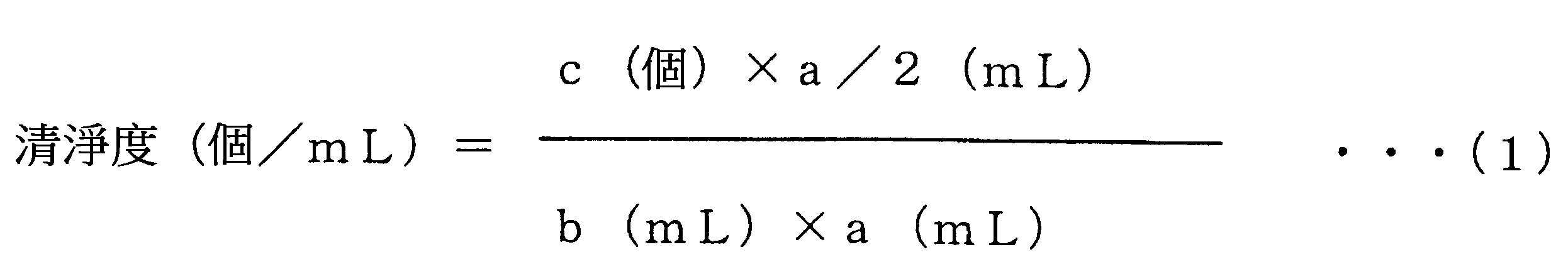
在數式(1)中,a係為檢查容器之容量,b係為從檢查容器中所取樣的液體之量。首先,如同下述一般地,而採取用以測定初期清淨度之樣本液。在容量a(mL)之檢查容器中,裝入容量之一半、亦即是a/2(mL)之超純水或者是光阻劑液,並進行15秒之震盪,並且靜置24小時,之後,進行採取。將用以測定收容後之清淨度的樣本液,在初期清淨度測定後之容器中安裝上栓體並作一定期間之放置,並在以不會產生氣泡的方式來將容器作了3圈旋轉之後,進行採取。c係為對於在樣本液全量中所包含之微粒子而藉由粒子計數器來作了計數後之值。基於該數值,來藉由式(1)而算出初期以及一定期間收容後之清淨度。若是清淨度之數值越低,則代表光阻劑液之品質越沒有劣化。若是清淨度為未滿100個/mL,則代表係並未導致光阻劑液之品質劣化地而作了收容。此種光阻劑液,係並不會使半導體或液晶顯示器(LCD)之品質以及良率降低。In formula (1), a is the capacity of the inspection container, and b is the amount of liquid sampled from the inspection container. First, sample liquid for measuring initial cleanliness is collected as follows. In the inspection container with a capacity of a (mL), fill half of the capacity, that is, a/2 (mL) of ultrapure water or photoresist solution, shake for 15 seconds, and let it stand for 24 hours. After that, take it. The sample liquid used to measure the cleanliness after containment is installed with a plug in the container after the initial cleanliness measurement and placed for a certain period of time, and the container is rotated 3 times in a way that does not generate air bubbles After that, take it. c is the value obtained by counting the fine particles contained in the total volume of the sample liquid with a particle counter. Based on this value, the cleanliness at the initial stage and after storage for a certain period of time is calculated by formula (1). The lower the value of the cleanliness, the less deterioration in the quality of the photoresist solution. If the cleanliness is less than 100 cells/mL, it means that the photoresist solution was stored without deteriorating the quality of the photoresist solution. This photoresist solution will not reduce the quality and yield of semiconductors or liquid crystal displays (LCDs).
作為用以形成容器10之高純度熱可塑性樹脂,係選擇在將容器10作為檢查容器而對於清淨度作了測定時會滿足特定之清淨度的樹脂。在收容光阻劑液的情況時,係使用清淨度為未滿100個/mL(特定之基準值之其中一例)之樹脂。換言之,所謂高純度熱可塑性樹脂,係指雜質微粒子不會超過特定之基準值地而滲出至液體中之樹脂。對應於所適用之規格,亦可採用清淨度為未滿200個/mL之樹脂。又,係亦可採用清淨度為未滿50個/mL、未滿10個/mL、未滿5個/mL、未滿3個/mL之樹脂。另外,容器之栓體(未圖示),較理想,係亦藉由高純度熱可塑性樹脂而形成。As the high-purity thermoplastic resin for forming the
又,除了清淨度以外,係亦可藉由液體之透明度之降低的程度(特定之基準值之另外一例),來規定雜質微粒子之滲出的程度。In addition, besides the cleanliness, the degree of exudation of impurity particles can also be specified by the degree of decrease in the transparency of the liquid (another example of a specific reference value).
形成容器10之樹脂,例如,係可列舉出像是聚乙烯以及聚丙烯一般之聚烯烴、聚醯胺、聚乙烯醇、乙烯-乙烯醇共聚物(poly(ethylene-co-vinyl alcohol))、聚酯、聚苯醚等。係亦可使用此些之樹脂之中之一種或二種以上來形成單層之容器,亦可使用此些之樹脂之複數種類來形成多層構造之容器。其中,又以聚乙烯為理想。具體而言,係可列舉出身為乙烯與α-烯烴之共聚物的直鏈狀聚乙烯(LLDPE)以及高密度聚乙烯(HDPE)。從剛性以及清淨度的觀點來看,較理想,係將容器10以高密度聚乙烯來形成。又,從保護環境的觀點來看,較理想,係使用能夠進行材料回收(material recycle)之樹脂。The resin forming the
高密度聚乙烯之熔體流動速率,較理想,係為0.01~3.0g/10分鐘,更理想,係為0.05~2.0g/10分鐘。又,其之密度,較理想,係為0.940~0.970g/cm 3,更理想,係為0.950~0.960g/cm 3。另外,熔體流動速率,係可準據於JIS K6760(1995)而求取出來。 The melt flow rate of high-density polyethylene is preferably 0.01-3.0 g/10 minutes, more preferably 0.05-2.0 g/10 minutes. Moreover, its density is preferably 0.940-0.970 g/cm 3 , more preferably 0.950-0.960 g/cm 3 . In addition, the melt flow rate can be calculated based on JIS K6760 (1995).
容器10中之至少內壁的表面,係亦可由密度0.940~0.970g/cm
3之聚乙烯或乙烯•α-烯烴共聚物之樹脂而成。此樹脂,較理想,係將藉由凝膠滲透色譜法所測定的重量平均分子量設為10×10
4~30×10
4,並將分子量為1×10
3以下之聚合物的含有率設為未滿2.5質量%,並且進而將藉由液相色譜法所定量出的中和劑、防氧化劑以及耐光安定劑的含有率分別設為0.01質量%以下。於此,α-烯烴,係亦可設為從由丙烯、丁烯-1、4-甲基-戊烯-1、己烯-1、辛烯-1而成之群中所選擇的至少一種類。若依據此種樹脂,則係能夠得到展現有高機械性強度,在處理性上為優良並且對於所收容之液體的雜質微粒子之滲出為極少的容器10。
At least the surface of the inner wall of the
容器10之材料,係亦可為包含有密度0.940~0.970g/cm
3之聚乙烯或乙烯•α-烯烴共聚物之樹脂和中和劑、防氧化劑以及耐光安定劑和包含無機顏料及/或有機顏料之遮光性顏料和具有2×10
3以上之數平均分子量的烯烴系聚合物之分散劑的樹脂組成物。此樹脂,較理想,係將藉由凝膠滲透色譜法所測定的重量平均分子量設為10×10
4~30×10
4,並將分子量為1×10
3以下之分子量設為未滿5質量%。在樹脂組成物中之中和劑、防氧化劑以及耐光安定劑之含有率,較理想,係分別為0.01質量%以下。作為上述之無機顏料,係可列舉出從氧化鈦、碳黑以及弁柄(bengala)中所選擇的至少一種,作為有機顏料,係可列舉出從酞菁系、喹吖啶系以及偶氮系有機顏料所選擇之至少一種。在樹脂組成物中之遮光性顏料的含有率,較理想,係為0.01~5質量%。烯烴系聚合物之分散劑之含有率,較理想,係為未滿5質量%。若依據此種樹脂組成物,則係能夠得到展現有高機械性強度,在處理性上為優良並且對於所收容之液體的雜質微粒子之滲出為極少而且能夠防止起因於光所造成的液體之變質的容器10。此種容器10,係適合對於半導體製造用藥液和上述之醫藥製造用溶劑作使用。
The material of the
容器10,係亦可具備有像是內層、中間層以及外層一般之層構造。於此情況,內層,較理想,係由高純度樹脂所成,該高純度樹脂,係包含有從藉由乙烯、丙烯、丁烯-1、4-甲基-戊烯-1、己烯-1以及辛烯-1所例示之烯烴聚合物和由乙烯以及其以外之烯烴之間之共聚物而成之群中所選擇的至少一種、與中和劑、防氧化劑以及耐光安定劑。於此情況,中和劑、防氧化劑以及耐光安定劑之含有率,較理想,係分別為最大0.01質量%。中間層,較理想,係包含有包含乙烯-乙烯醇共聚物之溶劑阻障性樹脂。又,係亦可在內層與中間層之間及/或中間層與外層之間,設置由馬來酸改性聚乙烯等所成之接著樹脂層。外層,較理想,係包含有包含遮光性物質之樹脂組成物。在此樹脂組成物中,係亦可包含有未滿5質量%之由具有2×10
3以上之數平均分子量的如同聚乙烯以及聚丙烯一般之烯烴系聚合物而成的顏料分散劑、和0.01~5重量%之包含有無機顏料及/或有機顏料之遮光性顏料,亦可包含有未滿2.5重量%之紫外線吸收劑。若依據此種層構造,則在液體之保管中以及輸送中,由於係並不會從容器10而滲出微粒子或金屬離子,因此係可得到能夠維持高純度液體之品質且難以破損並且為輕量之容器10。
The
支持台20以及把手30之材料,係並未特別作限定,而可為與容器10之材料相同,亦可為相異。例如,係可列舉出包含有由像是低密度聚乙烯、中密度聚乙烯、高密度聚乙烯、直鏈狀低密度聚乙烯、聚丙烯、聚丁烯、聚苯乙烯、聚醋酸乙烯、聚甲基丙烯酸甲酯、聚甲基丙烯酸乙酯、聚丙烯酸、環狀聚烯烴、聚丙烯腈、聚醯胺(尼龍)、聚對苯二甲酸乙二酯以及聚對苯二甲酸丁二酯一般之聚酯、聚胺酯、聚碳酸酯、聚醯亞胺、聚苯硫醚、聚氯乙烯而成之群之中之至少一者的單獨聚合物及/或共聚物及/或聚合物摻混物。The materials of the supporting
作為容器10之製造方法,雖係列舉了直接吹塑成形(壓出吹塑成形),但是,係亦可替代此,而採用像是注射吹塑成形(射出吹塑成形)、多層壓出吹塑成形以及延伸吹塑成形一般之周知之吹塑成形。又,支持台20以及把手30之製造方法,係以射出成形為理想。As the manufacturing method of the
作為被收容在容器10中之液體,例如,係可列舉出像是甲醇、乙醇、異丙醇、異丁醇、乙二醇、丙酮、乙酸乙酯、甲苯、二甲基甲醯胺、乙二醇乙酸酯、乙酸甲氧基丙酯以及丁基賽路蘇一般之液體化學品、光阻劑液以及洗淨液一般之半導體或液晶裝置之製造用藥液、消毒藥、輸液、透析液以及製劑原料一般之醫療、醫藥用藥液、香料、濃縮液、食品添加物一般之食品工業用藥液。
[實施例]
As the liquid contained in the
以下,列舉出實施例來對於本發明作更具體性之說明,但是,本發明係並不被限定於此些之實施例。Hereinafter, examples are given to describe the present invention more specifically, but the present invention is not limited to these examples.
(實施例1)
將身為容器10之材料的高密度聚乙烯樹脂(熔體流動速率0.3g/10分鐘、密度0.951g/cm
3、彎曲彈性模數1370MPa)熱熔融,並藉由擠壓機來壓出,而形成型坏。將此型坏以二分割模具來作包夾,並藉由直接吹塑成形而製作出了實施例1之容器10。此容器10,係具備有4個的凹部14,其之周方向長度H係為25mm,中心軸方向長度V係為6mm,並從分模線PL上之本體部12與階差部13之間之邊界場所起而分別作了30˚的分離。本體部12之最外周長度D係為160πmm,相對於最外周長度D之4個的凹部14之周方向長度H之比例、亦即是佔有率(H×N/D×100),係為20%。
(Example 1) A high-density polyethylene resin (melt flow rate: 0.3 g/10 minutes, density: 0.951 g/cm 3 , flexural modulus: 1370 MPa) which is the material of the
使用直鏈狀低密度聚乙烯樹脂(熔體流動速率4.0g/10分鐘、密度0.938g/cm
3),來藉由射出成形而製作了支持台20以及把手30。將支持台20與容器10作連結,並將把手螺合於容器10處,藉由此,而製作了容器組合體100。
The
(高壓時之形狀變化測定)
使用高度規(Height gauge)(MITUTOYO股份有限公司製),來作為容器10之常壓時全高度,而對於容器10之從本體部12之上端起直到圓底部15之下端為止的長度作了測定。在筒口11以及上端部12a處安裝加壓裝置,並將容器10之內壓昇壓至200kPa,並且將此於1小時內而保持為一定。在經過了1小時後的時間點處,再度對於容器10之全高度進行測定,並作為高壓時全高度而作了記錄。將相對於容器10之常壓時全高度之高壓時全高度的比例,作為全高度變化率而求取出來,其結果,係為0.61%。
(Measurement of shape change under high pressure)
Using a height gauge (manufactured by MITUTOYO Co., Ltd.), as the full height of the
(殘液量測定)
在容器10中收容2L之自來水,並將送液管(未圖示)從筒口11而筆直地插入至容器10內,並且以使其之末端位置在圓底部15之內壁面近旁處的方式而作了固定。對於容器10內施加0.05MPa之壓力,而將自來水從容器10排出,並在自來水成為了不會從送液管而排出時,停止壓力之施加,並且對於在容器10內所殘留的自來水之量作了測定,其結果,係為0.3mL。
(determination of residual liquid volume)
2L of tap water is accommodated in the
(實施例2)
將凹部14之周方向長度H變更為35mm,並將4個的凹部14之佔有率變更為28%,除此之外,係與實施例1相同地而進行操作,並製作出了實施例2之容器10。又,係與實施例1相同的而製作了支持台20以及把手30。將支持台20與容器10作連結,並將把手30螺合於容器10處,藉由此,而製作了容器組合體100。針對容器10而與實施例1相同地來進行操作並對於高壓時之形狀變化作測定,而求取出了全高度變化率,其結果,係為0.69%。
(Example 2)
The circumferential length H of the
(實施例3)
將凹部14以相互分離60˚的60˚間隔來設為6個,並將其之佔有率變更為30%,除此之外,係與實施例1相同地而進行操作,並製作出了實施例3之容器10。又,係與實施例1相同的而製作了支持台20以及把手30。將支持台20與容器10作連結,並將把手30螺合於容器10處,藉由此,而製作了容器組合體100。針對容器10而與實施例1相同地來進行操作並對於高壓時之形狀變化作測定,而求取出了全高度變化率,其結果,係為0.69%。
(Example 3)
The
(實施例4)
將凹部14之周方向長度H變更為35mm,並將6個的凹部14之佔有率變更為42%,除此之外,係與實施例3相同地而進行操作,並製作出了實施例4之容器10。又,係與實施例1相同的而製作了支持台20以及把手30。將支持台20與容器10作連結,並將把手30螺合於容器10處,藉由此,而製作了容器組合體100。針對容器10而與實施例1相同地來進行操作並對於高壓時之形狀變化作測定,而求取出了全高度變化率,其結果,係為0.86%。
(Example 4)
The length H of the circumferential direction of the
(實施例5)
將最外周長度D變更為360πmm,並將凹部14之周方向長度H設為50mm,並將6個的凹部14之佔有率變更為27%,並且將中心軸方向長度V變更為10mm,除此之外,係與實施例3相同地而進行操作,並製作出了實施例5之容器10。又,係與實施例1相同的而製作了支持台20以及把手30。將支持台20與容器10作連結,並將把手30螺合於容器10處,藉由此,而製作了容器組合體100。針對容器10而與實施例1相同地來進行操作並對於高壓時之形狀變化作測定,而求取出了全高度變化率,其結果,係為1.03%。又,係與實施例1相同地來進行操作並進行了殘液量測定,其結果,係為0.6mL。
(Example 5)
The outermost peripheral length D is changed to 360πmm, and the circumferential length H of the
(比較例1)
如同圖4中所示一般,將1個的凹部14,以會位置在從分模線PL上之本體部12與階差部13之間之邊界場所而離開角度θ=90˚之位置處的方式來作配置,並將1個的凹部14之佔有率變更為5%,除此之外,係與實施例1相同地而進行操作,並製作出了比較例1之容器10。又,係與實施例1相同的而製作了支持台20以及把手30。將支持台20與容器10作連結,並將把手30螺合於容器10處,藉由此,而製作了容器組合體100。針對容器10而與實施例1相同地來進行操作並將容器10之內壓昇壓至200kPa,其結果,容器10係從支持台20而脫落。因此,係並未對於全高度變化率作測定。
(comparative example 1)
As shown in FIG. 4, one
(比較例2)
如同圖5(a)中所示一般,替代凹部14,而涵蓋本體部42之下端之全周地來設置環繞溝44,並將環繞溝44之佔有率變更為100%,並且將容器40與把手40a作了一體成形,除此之外,係與實施例1相同地而進行操作,並製作出了比較例2之容器40。將與實施例1相同地進行操作所製作出的支持台20,與容器40作連結,而製作了容器組合體100。針對容器40而與實施例1相同地來進行操作並對於高壓時之形狀變化作測定,而求取出了全高度變化率,其結果,係為5.11%。又,係與實施例1相同地來進行操作並進行了殘液量測定,其結果,係為2.2mL。
(comparative example 2)
As shown in FIG. 5( a), instead of the
(比較例3)
將最外周長度D變更為360πmm,除此之外,係與比較例2相同地而進行操作,並製作出了比較例3之容器40。將與比較例2相同地進行操作所製作出的支持台20,與容器40作連結,而製作了容器組合體100。針對容器40而與實施例1相同地來進行操作並對於高壓時之形狀變化作測定,而求取出了全高度變化率,其結果,係為7.37%。
(comparative example 3)
Except having changed the outermost peripheral length D into 360πmm, it operated similarly to the comparative example 2, and produced the
(比較例4)
如同圖5(b)中所示一般,並不設置凹部14,並且替代圓底部15而形成了平底部45,除此之外,係與比較例2相同地而進行操作,藉由此,而製作出了就算是沒有支持台也能夠自立的比較例4之容器40。針對容器40而與實施例1相同地來進行操作並將容器之內壓昇壓至200kPa,其結果,平底部45係膨脹隆起,容器40係倒下。在針對倒下的容器40而求取出全高度變化率之後,其結果,係為4.10%。
(comparative example 4)
As shown in FIG. 5( b ), except that the
將在實施例1~5中之容器10以及比較例1~4中之容器之構成以及高壓時之形狀變化測定和殘液量測定之結果,統整展示於表1中。Table 1 shows the configuration of the
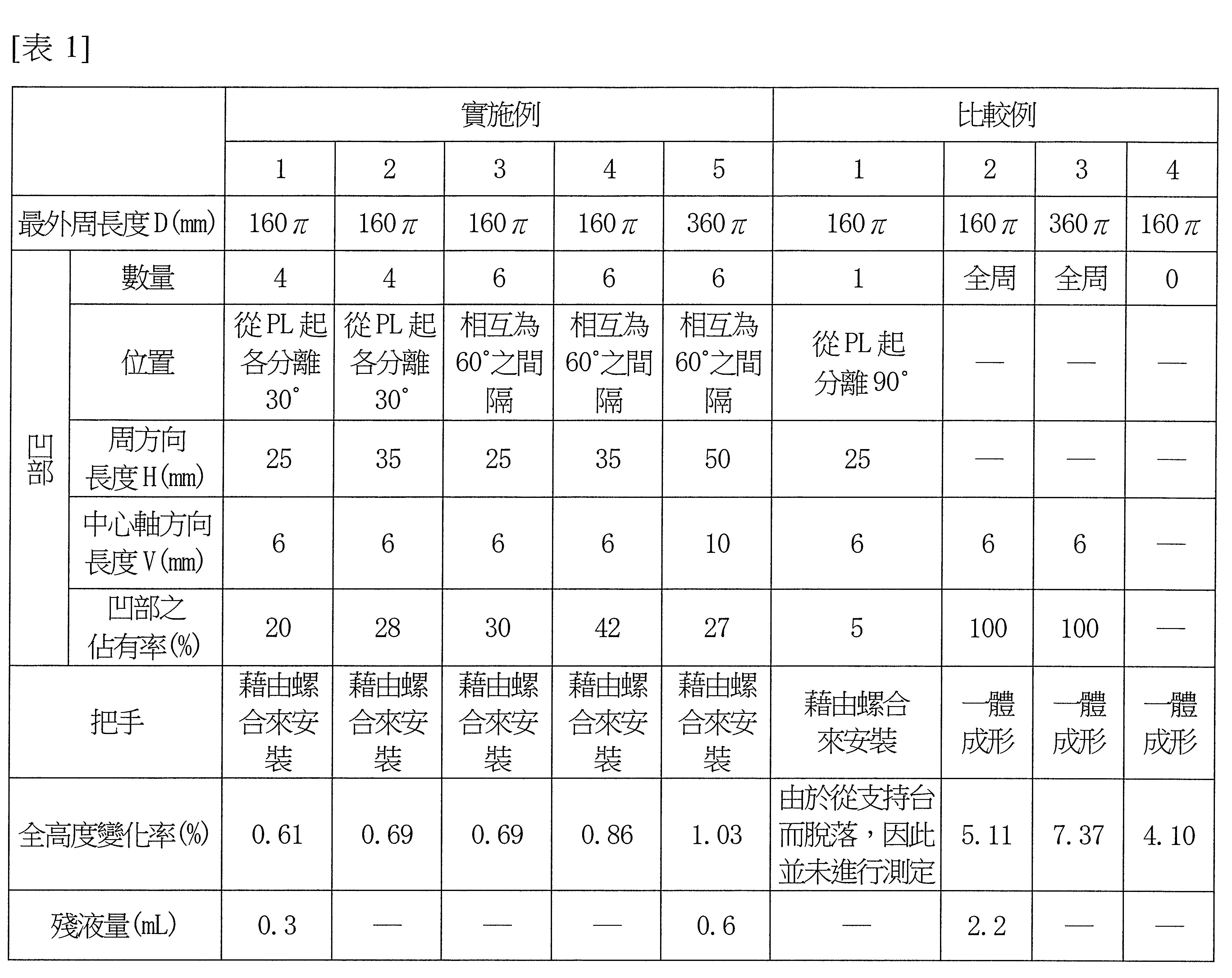
如同根據表1而可得知一般,實施例1~5之容器10,由於凹部14係均未伸長,因此,就算是容器10內為高壓,或者是並不使用對於容器10之全高度變化作抑制的容器支持具,其之全高度也幾乎不會變化。另一方面,在比較例1中,由於凹部14係僅有1個,因此,容器10與支持台20之間之卡合係為不安定,故而容器10係從支持台20而脫落。又,替代凹部14而設為涵蓋容器40之全周之連續的環繞溝44之比較例2以及3,係由於起因於容器40內之昇壓而導致環繞溝44如同渦捲彈簧一般地伸長並擴廣,因此容器之全高度係顯著地有所伸長。
[產業上的利用可能性]
As can be seen from Table 1, the
本發明之容器以及容器組合體,例如,係可合適使用在對於清淨之品質的液體有所需求之半導體和液晶裝置之製造領域、醫藥品領域以及食品領域中的液體之壓送中。The container and container assembly of the present invention can be suitably used, for example, for liquid pressure delivery in the field of manufacturing semiconductors and liquid crystal devices, the field of pharmaceuticals, and the field of food that require liquids of clean quality.
10:容器
11:筒口
12:本體部
12a:上端部
12a
1:公螺紋
12b:頸部
12b
1:公螺紋
12c:胴體部
13:階差部
14:凹部
15:圓底部
20:支持台
21:爪部
30:把手
31:環狀部
31a:安裝孔
31b:母螺紋
32:握把部
32a:勾指孔
40:容器
40a:把手
42:本體部
44:環繞溝
45:平底部
100:容器組合體
C:中心軸
D:最外周長度
H:周方向長度
h:中心點
PL:分模線
V:中心軸方向長度
X,Y:基準線
θ,θ
1:角度
10: Container 11: Mouth 12:
[圖1]係為對於適用本發明之容器作展示的正面圖以及A-A線箭頭方向觀察端面圖。 [圖2]係為對於適用本發明之容器組合體作展示的立體圖以及分解立體圖。 [圖3]係為對於適用本發明之容器的其他例作展示之端面圖。 [圖4]係為並未適用本發明的比較例1之容器之端面圖。 [圖5]係為並未適用本發明的比較例2以及4之容器之立體圖。 [Fig. 1] is a front view showing a container to which the present invention is applied and an end view viewed from the direction of the arrow A-A. [ Fig. 2 ] is a perspective view and an exploded perspective view showing a container assembly to which the present invention is applied. [ Fig. 3 ] is an end view showing another example of a container to which the present invention is applied. [ Fig. 4 ] is an end view of a container of Comparative Example 1 to which the present invention is not applied. [ Fig. 5 ] is a perspective view of containers of Comparative Examples 2 and 4 to which the present invention is not applied.
10:容器 10: container
11:筒口 11: barrel mouth
12:本體部 12: Main body
12a:上端部 12a: upper end
12a1:公螺紋 12a 1 : Male thread
12b:頸部 12b: Neck
12b1:公螺紋 12b 1 : Male thread
12c:胴體部 12c: carcass
13:階差部 13: Step Department
14:凹部 14: Concave
15:圓底部 15: round bottom
C:中心軸 C: central axis
H:周方向長度 H: Length in the circumferential direction
h:中心點 h: center point
PL:分模線 PL: parting line
V:中心軸方向長度 V: Length in direction of central axis
X,Y:基準線 X, Y: reference line
θ:角度 θ: angle
Claims (4)
Applications Claiming Priority (2)
| Application Number | Priority Date | Filing Date | Title |
|---|---|---|---|
| JP2021-083228 | 2021-05-17 | ||
| JP2021083228A JP7013610B1 (en) | 2021-05-17 | 2021-05-17 | Containers and container assemblies |
Publications (2)
| Publication Number | Publication Date |
|---|---|
| TW202246135A TW202246135A (en) | 2022-12-01 |
| TWI802412B true TWI802412B (en) | 2023-05-11 |
Family
ID=80737852
Family Applications (1)
| Application Number | Title | Priority Date | Filing Date |
|---|---|---|---|
| TW111118161A TWI802412B (en) | 2021-05-17 | 2022-05-16 | Containers and container assemblies |
Country Status (7)
| Country | Link |
|---|---|
| US (1) | US12384596B2 (en) |
| EP (1) | EP4342811B1 (en) |
| JP (1) | JP7013610B1 (en) |
| KR (1) | KR102607395B1 (en) |
| CN (1) | CN117320970B (en) |
| TW (1) | TWI802412B (en) |
| WO (1) | WO2022244527A1 (en) |
Families Citing this family (4)
| Publication number | Priority date | Publication date | Assignee | Title |
|---|---|---|---|---|
| SE544653C2 (en) * | 2020-07-08 | 2022-10-04 | Aarke Ab | Beverage bottle and method for joining thereof |
| JP7013610B1 (en) * | 2021-05-17 | 2022-01-31 | 株式会社アイセロ | Containers and container assemblies |
| JP2024066898A (en) | 2022-11-02 | 2024-05-16 | 旭化成株式会社 | Solid electrolyte laminate, solid secondary battery, and method for manufacturing the same |
| JP2025068429A (en) * | 2023-10-16 | 2025-04-28 | 株式会社アイセロ | Dip nozzle, and liquid container using the same |
Citations (7)
| Publication number | Priority date | Publication date | Assignee | Title |
|---|---|---|---|---|
| JPS5726337U (en) * | 1980-07-22 | 1982-02-10 | ||
| JPH01147983U (en) * | 1988-03-31 | 1989-10-13 | ||
| JPH072233U (en) * | 1993-06-15 | 1995-01-13 | 広幸 麻生 | Beer bottle and one shobo handle |
| JP2000010390A (en) * | 1998-06-24 | 2000-01-14 | Sharp Corp | Developer container |
| TW442429B (en) * | 1998-05-08 | 2001-06-23 | Aicello Chemical Co | Container for high purity liquid chemicals |
| JP2019001508A (en) * | 2017-06-15 | 2019-01-10 | 株式会社吉野工業所 | Container with cap |
| JP2020196537A (en) * | 2019-05-31 | 2020-12-10 | シャープ株式会社 | Container and container set |
Family Cites Families (39)
| Publication number | Priority date | Publication date | Assignee | Title |
|---|---|---|---|---|
| US845777A (en) * | 1906-10-27 | 1907-03-05 | Joseph Grossman | Milk-bottle protector. |
| US860316A (en) * | 1907-03-18 | 1907-07-16 | Louis P Nash | Casing for siphon-bottles. |
| US2837245A (en) * | 1955-05-12 | 1958-06-03 | Injection Molding Company | Low pressure flexible wall container |
| US2905351A (en) * | 1956-02-27 | 1959-09-22 | Braun Co W | Snap-on base for a bottle, jar, glass, or the like |
| US3847494A (en) * | 1970-08-19 | 1974-11-12 | E Franklin | Coupling mechanism for tubular elements |
| US3722725A (en) * | 1970-09-24 | 1973-03-27 | Monsanto Co | Package for pressurized fluent materials a |
| US3927782A (en) * | 1974-07-02 | 1975-12-23 | Illinois Tool Works | Plastic container and base construction |
| US3948404A (en) * | 1974-11-14 | 1976-04-06 | E. I. Du Pont De Nemours And Company | Composite package for containing pressurized fluids |
| FR2357437A1 (en) * | 1976-07-07 | 1978-02-03 | Carnaud Total Interplastic | HOLLOW BODY IN PLASTIC MATERIAL SUBJECT TO INTERNAL PRESSURE |
| DE2731635C2 (en) * | 1976-07-16 | 1985-07-25 | Owens-Illinois, Inc., Toledo, Ohio | Bottle made of biaxially oriented polyester |
| US4241839A (en) * | 1979-08-14 | 1980-12-30 | Sewell Plastics, Inc. | Base-cup for assuring vertical alignment of semi-hemispherically bottomed bottles |
| US4463860A (en) * | 1980-03-03 | 1984-08-07 | Yoshino Kogyosho Co., Ltd. | Saturated polyester resin bottle and stand |
| US4326638A (en) * | 1980-05-16 | 1982-04-27 | Plastipak Packaging Division, Beatrice Food Co. | Combination base cup and bottle |
| JPS5726337A (en) * | 1980-07-23 | 1982-02-12 | Mitsubishi Electric Corp | Controller for air conditioner |
| JPS5876899A (en) | 1981-10-31 | 1983-05-10 | 株式会社東芝 | Voice segment detector |
| JPS5876899U (en) | 1981-11-19 | 1983-05-24 | 大日本インキ化学工業株式会社 | Container with freestanding holder |
| JPH01147938A (en) * | 1987-12-03 | 1989-06-09 | Matsushita Electric Ind Co Ltd | Communication equipment |
| US4881666A (en) * | 1988-01-19 | 1989-11-21 | Robert Tullman | Variable volume container |
| JP3016052B2 (en) * | 1992-05-15 | 2000-03-06 | 東洋自動機株式会社 | Degassing device for automatic packaging machine |
| US5662241A (en) * | 1995-07-03 | 1997-09-02 | Sorensen; Charles K. | Container and stand for liquids |
| US6405675B1 (en) * | 2000-08-11 | 2002-06-18 | Julie M. Mills | Water bottle assembly having a removable water bowl |
| DE20201737U1 (en) * | 2002-02-05 | 2003-04-30 | Münch, Hans, 82024 Taufkirchen | Repeatedly usable bottle for drinks containing carbon dioxide gas comprises a machine-washable bottle body provided with grooves serving for attachment of the bottle base |
| US20060177399A1 (en) * | 2004-11-16 | 2006-08-10 | Herve Jourdan | Pressurized device for hair fiber styling and use of the same for hair fiber styling and/or hair |
| BRMU8500295Y1 (en) * | 2005-02-23 | 2014-01-14 | CONSTRUCTIVE PROVISION ON PACKAGING OF MEDICINAL PRODUCTS AND COSMETICS | |
| CN200988621Y (en) * | 2006-11-01 | 2007-12-12 | 美的集团有限公司 | Connecting device of electric heating container |
| CN201056328Y (en) * | 2007-07-13 | 2008-05-07 | 广东奥飞动漫文化股份有限公司 | Packaging can for conveniently piling up remote control toy car |
| US9061795B2 (en) * | 2007-08-20 | 2015-06-23 | Procter & Gamble | Supportable pressurizable container and base cup therefor with alignment tabs |
| US20090050599A1 (en) * | 2007-08-20 | 2009-02-26 | Matthew John Martin | Supportable pressurizable container having a bottom for receiving a dip tube and base cup therefor |
| US8439223B2 (en) * | 2007-08-20 | 2013-05-14 | The Procter & Gamble Company | Base cup for a supportable pressurizable container |
| US20090184116A1 (en) * | 2008-01-23 | 2009-07-23 | Laske Lawrence L | Portable, nestable storage and carrying means for food and drink having integrated releasable serving means |
| CN201249910Y (en) * | 2008-04-30 | 2009-06-03 | 陈勇 | Storage type bottle base |
| CN201390477Y (en) * | 2009-03-20 | 2010-01-27 | 吴伟坚 | Wine bottle |
| JP5560019B2 (en) | 2009-11-04 | 2014-07-23 | 株式会社アイセロ | Liquid feeding device and liquid container used for the liquid feeding device |
| US8453860B2 (en) * | 2011-09-12 | 2013-06-04 | Efrain Otero | Bottle with ratcheting base and inner bladder |
| AU2015402777B2 (en) | 2015-07-23 | 2019-03-14 | Colgate-Palmolive Company | Container closure and preform |
| US20180296013A1 (en) * | 2016-12-08 | 2018-10-18 | Matthew Richad Frei | Container Inverter |
| CN112770978B (en) * | 2018-11-30 | 2022-12-16 | 京洛株式会社 | container with lid |
| CN211495203U (en) | 2019-09-02 | 2020-09-15 | 陕西西氢航天动力科技有限公司 | Sealing device capable of being rapidly disassembled and assembled under high-temperature environment |
| JP7013610B1 (en) * | 2021-05-17 | 2022-01-31 | 株式会社アイセロ | Containers and container assemblies |
-
2021
- 2021-05-17 JP JP2021083228A patent/JP7013610B1/en active Active
-
2022
- 2022-03-31 KR KR1020237004487A patent/KR102607395B1/en active Active
- 2022-03-31 US US18/561,003 patent/US12384596B2/en active Active
- 2022-03-31 WO PCT/JP2022/016522 patent/WO2022244527A1/en not_active Ceased
- 2022-03-31 EP EP22804443.4A patent/EP4342811B1/en active Active
- 2022-03-31 CN CN202280036120.XA patent/CN117320970B/en active Active
- 2022-05-16 TW TW111118161A patent/TWI802412B/en not_active IP Right Cessation
Patent Citations (7)
| Publication number | Priority date | Publication date | Assignee | Title |
|---|---|---|---|---|
| JPS5726337U (en) * | 1980-07-22 | 1982-02-10 | ||
| JPH01147983U (en) * | 1988-03-31 | 1989-10-13 | ||
| JPH072233U (en) * | 1993-06-15 | 1995-01-13 | 広幸 麻生 | Beer bottle and one shobo handle |
| TW442429B (en) * | 1998-05-08 | 2001-06-23 | Aicello Chemical Co | Container for high purity liquid chemicals |
| JP2000010390A (en) * | 1998-06-24 | 2000-01-14 | Sharp Corp | Developer container |
| JP2019001508A (en) * | 2017-06-15 | 2019-01-10 | 株式会社吉野工業所 | Container with cap |
| JP2020196537A (en) * | 2019-05-31 | 2020-12-10 | シャープ株式会社 | Container and container set |
Also Published As
| Publication number | Publication date |
|---|---|
| TW202246135A (en) | 2022-12-01 |
| US20240367857A1 (en) | 2024-11-07 |
| JP7013610B1 (en) | 2022-01-31 |
| WO2022244527A1 (en) | 2022-11-24 |
| CN117320970B (en) | 2025-12-12 |
| KR102607395B1 (en) | 2023-11-29 |
| KR20230025526A (en) | 2023-02-21 |
| JP2022176682A (en) | 2022-11-30 |
| CN117320970A (en) | 2023-12-29 |
| EP4342811B1 (en) | 2026-02-11 |
| EP4342811A4 (en) | 2025-04-23 |
| US12384596B2 (en) | 2025-08-12 |
| EP4342811A1 (en) | 2024-03-27 |
Similar Documents
| Publication | Publication Date | Title |
|---|---|---|
| TWI802412B (en) | Containers and container assemblies | |
| CN102050248B (en) | Liquid container, liquid delivering device equipped therewith | |
| US7308991B2 (en) | Blown bottle with intrinsic liner | |
| US8733598B2 (en) | Closure/connector for liner-based dispense containers | |
| JP6354015B2 (en) | Connector for liner-based dispensing containers | |
| CN101472808B (en) | Containers for fluids and containers filled with fluids using the containers for fluids | |
| EP2376346B1 (en) | Storage system with rigid liner and method of delivering a fluid | |
| EP2774871A1 (en) | Discharge container | |
| WO2000000399A1 (en) | Container and blow-molded product | |
| CN102372106A (en) | 60 liters inner bag composite container | |
| CN104691906A (en) | Dispensing device for inner bag composite container, and method for manufacturing same | |
| JP5222390B2 (en) | Container for fluid and container containing fluid using the same | |
| JP5415517B2 (en) | Container for fluid and container containing fluid using the same | |
| WO2014066723A1 (en) | Breakseal | |
| JP3176540B2 (en) | High purity resin composition and molded article of the resin composition | |
| JP4917811B2 (en) | Stackable plastic containers | |
| CN121263369A (en) | Immersion nozzle and liquid container using the same | |
| TWI605983B (en) | Substantially rigid collapsible liner and flexible gusseted or non-gusseted liners and methods of manufacturing the same and methods for limiting choke-off in liners | |
| JP2021104849A (en) | Double container | |
| CN104936718A (en) | Manufacturing method for three-dimensional conformal lining of ordinary cylinder |
Legal Events
| Date | Code | Title | Description |
|---|---|---|---|
| MM4A | Annulment or lapse of patent due to non-payment of fees |