US10022154B2 - Femoral and tibial base components - Google Patents
Femoral and tibial base components Download PDFInfo
- Publication number
- US10022154B2 US10022154B2 US12/112,442 US11244208A US10022154B2 US 10022154 B2 US10022154 B2 US 10022154B2 US 11244208 A US11244208 A US 11244208A US 10022154 B2 US10022154 B2 US 10022154B2
- Authority
- US
- United States
- Prior art keywords
- bone
- base component
- base
- openings
- joint
- Prior art date
- Legal status (The legal status is an assumption and is not a legal conclusion. Google has not performed a legal analysis and makes no representation as to the accuracy of the status listed.)
- Active, expires
Links
Images




Classifications
-
- A—HUMAN NECESSITIES
- A61—MEDICAL OR VETERINARY SCIENCE; HYGIENE
- A61B—DIAGNOSIS; SURGERY; IDENTIFICATION
- A61B17/00—Surgical instruments, devices or methods
- A61B17/56—Surgical instruments or methods for treatment of bones or joints; Devices specially adapted therefor
- A61B17/58—Surgical instruments or methods for treatment of bones or joints; Devices specially adapted therefor for osteosynthesis, e.g. bone plates, screws or setting implements
- A61B17/68—Internal fixation devices, including fasteners and spinal fixators, even if a part thereof projects from the skin
-
- A—HUMAN NECESSITIES
- A61—MEDICAL OR VETERINARY SCIENCE; HYGIENE
- A61B—DIAGNOSIS; SURGERY; IDENTIFICATION
- A61B17/00—Surgical instruments, devices or methods
- A61B17/56—Surgical instruments or methods for treatment of bones or joints; Devices specially adapted therefor
-
- A—HUMAN NECESSITIES
- A61—MEDICAL OR VETERINARY SCIENCE; HYGIENE
- A61F—FILTERS IMPLANTABLE INTO BLOOD VESSELS; PROSTHESES; DEVICES PROVIDING PATENCY TO, OR PREVENTING COLLAPSING OF, TUBULAR STRUCTURES OF THE BODY, e.g. STENTS; ORTHOPAEDIC, NURSING OR CONTRACEPTIVE DEVICES; FOMENTATION; TREATMENT OR PROTECTION OF EYES OR EARS; BANDAGES, DRESSINGS OR ABSORBENT PADS; FIRST-AID KITS
- A61F2/00—Filters implantable into blood vessels; Prostheses, i.e. artificial substitutes or replacements for parts of the body; Appliances for connecting them with the body; Devices providing patency to, or preventing collapsing of, tubular structures of the body, e.g. stents
- A61F2/02—Prostheses implantable into the body
- A61F2/08—Muscles; Tendons; Ligaments
- A61F2/0811—Fixation devices for tendons or ligaments
-
- A—HUMAN NECESSITIES
- A61—MEDICAL OR VETERINARY SCIENCE; HYGIENE
- A61B—DIAGNOSIS; SURGERY; IDENTIFICATION
- A61B17/00—Surgical instruments, devices or methods
- A61B17/56—Surgical instruments or methods for treatment of bones or joints; Devices specially adapted therefor
- A61B17/58—Surgical instruments or methods for treatment of bones or joints; Devices specially adapted therefor for osteosynthesis, e.g. bone plates, screws or setting implements
- A61B17/60—Surgical instruments or methods for treatment of bones or joints; Devices specially adapted therefor for osteosynthesis, e.g. bone plates, screws or setting implements for external osteosynthesis, e.g. distractors, contractors
- A61B17/64—Devices extending alongside the bones to be positioned
- A61B17/6425—Devices extending alongside the bones to be positioned specially adapted to be fitted across a bone joint
-
- A—HUMAN NECESSITIES
- A61—MEDICAL OR VETERINARY SCIENCE; HYGIENE
- A61B—DIAGNOSIS; SURGERY; IDENTIFICATION
- A61B17/00—Surgical instruments, devices or methods
- A61B17/56—Surgical instruments or methods for treatment of bones or joints; Devices specially adapted therefor
- A61B17/58—Surgical instruments or methods for treatment of bones or joints; Devices specially adapted therefor for osteosynthesis, e.g. bone plates, screws or setting implements
- A61B17/68—Internal fixation devices, including fasteners and spinal fixators, even if a part thereof projects from the skin
- A61B17/80—Cortical plates, i.e. bone plates; Instruments for holding or positioning cortical plates, or for compressing bones attached to cortical plates
- A61B17/8061—Cortical plates, i.e. bone plates; Instruments for holding or positioning cortical plates, or for compressing bones attached to cortical plates specially adapted for particular bones
-
- A—HUMAN NECESSITIES
- A61—MEDICAL OR VETERINARY SCIENCE; HYGIENE
- A61B—DIAGNOSIS; SURGERY; IDENTIFICATION
- A61B17/00—Surgical instruments, devices or methods
- A61B17/56—Surgical instruments or methods for treatment of bones or joints; Devices specially adapted therefor
- A61B17/58—Surgical instruments or methods for treatment of bones or joints; Devices specially adapted therefor for osteosynthesis, e.g. bone plates, screws or setting implements
- A61B17/68—Internal fixation devices, including fasteners and spinal fixators, even if a part thereof projects from the skin
- A61B17/80—Cortical plates, i.e. bone plates; Instruments for holding or positioning cortical plates, or for compressing bones attached to cortical plates
- A61B17/8085—Cortical plates, i.e. bone plates; Instruments for holding or positioning cortical plates, or for compressing bones attached to cortical plates with pliable or malleable elements or having a mesh-like structure, e.g. small strips
-
- A—HUMAN NECESSITIES
- A61—MEDICAL OR VETERINARY SCIENCE; HYGIENE
- A61B—DIAGNOSIS; SURGERY; IDENTIFICATION
- A61B17/00—Surgical instruments, devices or methods
- A61B17/56—Surgical instruments or methods for treatment of bones or joints; Devices specially adapted therefor
- A61B17/58—Surgical instruments or methods for treatment of bones or joints; Devices specially adapted therefor for osteosynthesis, e.g. bone plates, screws or setting implements
- A61B17/68—Internal fixation devices, including fasteners and spinal fixators, even if a part thereof projects from the skin
- A61B17/80—Cortical plates, i.e. bone plates; Instruments for holding or positioning cortical plates, or for compressing bones attached to cortical plates
- A61B17/809—Cortical plates, i.e. bone plates; Instruments for holding or positioning cortical plates, or for compressing bones attached to cortical plates with bone-penetrating elements, e.g. blades or prongs
-
- A—HUMAN NECESSITIES
- A61—MEDICAL OR VETERINARY SCIENCE; HYGIENE
- A61B—DIAGNOSIS; SURGERY; IDENTIFICATION
- A61B17/00—Surgical instruments, devices or methods
- A61B17/56—Surgical instruments or methods for treatment of bones or joints; Devices specially adapted therefor
- A61B2017/567—Joint mechanisms or joint supports in addition to the natural joints and outside the joint gaps
-
- A—HUMAN NECESSITIES
- A61—MEDICAL OR VETERINARY SCIENCE; HYGIENE
- A61F—FILTERS IMPLANTABLE INTO BLOOD VESSELS; PROSTHESES; DEVICES PROVIDING PATENCY TO, OR PREVENTING COLLAPSING OF, TUBULAR STRUCTURES OF THE BODY, e.g. STENTS; ORTHOPAEDIC, NURSING OR CONTRACEPTIVE DEVICES; FOMENTATION; TREATMENT OR PROTECTION OF EYES OR EARS; BANDAGES, DRESSINGS OR ABSORBENT PADS; FIRST-AID KITS
- A61F2/00—Filters implantable into blood vessels; Prostheses, i.e. artificial substitutes or replacements for parts of the body; Appliances for connecting them with the body; Devices providing patency to, or preventing collapsing of, tubular structures of the body, e.g. stents
- A61F2/02—Prostheses implantable into the body
- A61F2/08—Muscles; Tendons; Ligaments
-
- A—HUMAN NECESSITIES
- A61—MEDICAL OR VETERINARY SCIENCE; HYGIENE
- A61F—FILTERS IMPLANTABLE INTO BLOOD VESSELS; PROSTHESES; DEVICES PROVIDING PATENCY TO, OR PREVENTING COLLAPSING OF, TUBULAR STRUCTURES OF THE BODY, e.g. STENTS; ORTHOPAEDIC, NURSING OR CONTRACEPTIVE DEVICES; FOMENTATION; TREATMENT OR PROTECTION OF EYES OR EARS; BANDAGES, DRESSINGS OR ABSORBENT PADS; FIRST-AID KITS
- A61F2/00—Filters implantable into blood vessels; Prostheses, i.e. artificial substitutes or replacements for parts of the body; Appliances for connecting them with the body; Devices providing patency to, or preventing collapsing of, tubular structures of the body, e.g. stents
- A61F2/02—Prostheses implantable into the body
- A61F2/08—Muscles; Tendons; Ligaments
- A61F2/0811—Fixation devices for tendons or ligaments
- A61F2002/0817—Structure of the anchor
- A61F2002/0823—Modular anchors comprising a plurality of separate parts
- A61F2002/0829—Modular anchors comprising a plurality of separate parts without deformation of anchor parts, e.g. fixation screws on bone surface, extending barbs, cams, butterflies, spring-loaded pins
-
- A—HUMAN NECESSITIES
- A61—MEDICAL OR VETERINARY SCIENCE; HYGIENE
- A61F—FILTERS IMPLANTABLE INTO BLOOD VESSELS; PROSTHESES; DEVICES PROVIDING PATENCY TO, OR PREVENTING COLLAPSING OF, TUBULAR STRUCTURES OF THE BODY, e.g. STENTS; ORTHOPAEDIC, NURSING OR CONTRACEPTIVE DEVICES; FOMENTATION; TREATMENT OR PROTECTION OF EYES OR EARS; BANDAGES, DRESSINGS OR ABSORBENT PADS; FIRST-AID KITS
- A61F2/00—Filters implantable into blood vessels; Prostheses, i.e. artificial substitutes or replacements for parts of the body; Appliances for connecting them with the body; Devices providing patency to, or preventing collapsing of, tubular structures of the body, e.g. stents
- A61F2/02—Prostheses implantable into the body
- A61F2/08—Muscles; Tendons; Ligaments
- A61F2/0811—Fixation devices for tendons or ligaments
- A61F2002/0847—Mode of fixation of anchor to tendon or ligament
- A61F2002/0864—Fixation of tendon or ligament between anchor elements, e.g. by additional screws in the anchor, anchor crimped around tendon
-
- A—HUMAN NECESSITIES
- A61—MEDICAL OR VETERINARY SCIENCE; HYGIENE
- A61F—FILTERS IMPLANTABLE INTO BLOOD VESSELS; PROSTHESES; DEVICES PROVIDING PATENCY TO, OR PREVENTING COLLAPSING OF, TUBULAR STRUCTURES OF THE BODY, e.g. STENTS; ORTHOPAEDIC, NURSING OR CONTRACEPTIVE DEVICES; FOMENTATION; TREATMENT OR PROTECTION OF EYES OR EARS; BANDAGES, DRESSINGS OR ABSORBENT PADS; FIRST-AID KITS
- A61F2/00—Filters implantable into blood vessels; Prostheses, i.e. artificial substitutes or replacements for parts of the body; Appliances for connecting them with the body; Devices providing patency to, or preventing collapsing of, tubular structures of the body, e.g. stents
- A61F2/02—Prostheses implantable into the body
- A61F2/08—Muscles; Tendons; Ligaments
- A61F2/0811—Fixation devices for tendons or ligaments
- A61F2002/0876—Position of anchor in respect to the bone
- A61F2002/0888—Anchor in or on a blind hole or on the bone surface without formation of a tunnel
Definitions
- Joint replacement is one of the most common and successful operations in modern orthopaedic surgery. It consists of replacing painful, arthritic, worn or diseased parts of a joint with artificial surfaces shaped in such a way as to allow joint movement. Osteoarthritis is a common diagnosis leading to joint replacement. Such procedures are a last resort treatment as they are highly invasive and require substantial periods of recovery.
- Total joint replacement also known as total joint arthroplasty, is a procedure in which all articular surfaces at a joint are replaced.
- arthroplasty procedures are also characterized by relatively long recovery times and their highly invasive procedures.
- a previously popular form of arthroplasty was interpositional arthroplasty in which the joint was surgically altered by insertion of some other tissue like skin, muscle or tendon within the articular space to keep inflammatory surfaces apart.
- Another previously done arthroplasty was excisional arthroplasty in which articular surfaces were removed leaving scar tissue to fill in the gap.
- resection(al) arthroplasty, resurfacing arthroplasty, mold arthroplasty, cup arthroplasty, silicone replacement arthroplasty, and osteotomy to affect joint alignment or restore or modify joint congruity.
- arthroplasty results in new joint surfaces which serve the same function in the joint as did the surfaces that were removed.
- Any chodrocytes (cells that control the creation and maintenance of articular joint surfaces), however, are either removed as part of the arthroplasty, or left to contend with the resulting joint anatomy. Because of this, none of these currently available therapies are chondro-protective.
- a widely-applied type of osteotomy is one in which bones are surgically cut to improve alignment.
- a misalignment due to injury or disease in a joint relative to the direction of load can result in an imbalance of forces and pain in the affected joint.
- the goal of osteotomy is to surgically re-align the bones at a joint and thereby relieve pain by equalizing forces across the joint. This can also increase the lifespan of the joint.
- this procedure involves surgical re-alignment of the joint by cutting and reattaching part of one of the bones at the knee to change the joint alignment, and this procedure is often used in younger, more active or heavier patients.
- the natural joint is a construct comprised of elements of different compliance characteristics such as bone, cartilage, synovial fluid, muscles, tendons, ligaments, etc. as described above.
- These dynamic elements include relatively compliant ones (ligaments, tendons, fluid, cartilage) which allow for substantial energy absorption and storage, and relatively stiffer ones (bone) that allow for efficient energy transfer.
- the cartilage in a joint compresses under applied force and the resultant force displacement product represents the energy absorbed by cartilage.
- the fluid content of cartilage also acts to stiffen its response to load applied quickly and dampen its response to loads applied slowly. In this way, cartilage acts to absorb and store, as well as to dissipate energy.
- the base component includes a body having an inner surface that is contoured to mate with a bone surface.
- the inner surface contacts the bone surface and may be porous, roughened or etched to promote osteointegration.
- the inner surface can be coated with an osteointegration composition.
- the base component is secured to a bone surface with a plurality of fastening members.
- the base component is also shaped to avoid and preserve structures of the knee.
- the base component is configured to locate a mounting member on the bone in order to position a kinematic load absorber for optimal reduction of forces on a joint.
- the base component is a rigid structure that may be made from titanium, cobalt chrome, or polyetheretherketones (PEEK).
- the base can be formed at least partially from flexible material.
- the base component is a generally curved body having a first end, a second end, an outer surface, and an inner surface.
- the curved body is non-planar such that the second end of the body is elevated as compared to the first end of the body.
- the inner surface of the body includes a raised portion that is contoured to the medial surface of the femur above the medial epicondyle.
- the body also includes a plurality of openings, wherein two openings are positioned side-by-side near the second end. Additionally, the openings provide differing trajectories for receiving fastening members.
- various sized bases be made available.
- the bases can be configured so that relative motion between a base component and a mating bone is less than 150 microns.
- the durability of the base to bone connection as well as material should be such that the structure can withstand five million cycles of functional loading.
- FIG. 1A is a perspective view of one embodiment of a base component.
- FIG. 1B is a perspective view of the base component of FIG. 1A mounted to a bone.
- FIG. 1C is a perspective view of another embodiment of a base component.
- FIG. 1D is a side view depicting the base component of FIG. 1C mounted to a bone.
- FIG. 11 is a side view of one embodiment of a base component fixed to a femur.
- FIG. 14 is a perspective view of an inner surface of the base component shown in FIG. 13 .
- FIG. 15A is a cross-section view of one embodiment of the base component shown in FIG. 14 .
- FIG. 16 is a front view of the base component of FIG. 13 mounted to the medial surface of a tibia.
- FIG. 22 is a perspective view of another embodiment of a base.
- the femoral and tibial base components are contoured to the medial surfaces of the femur and tibia, respectively.
- the base components have a low-profile design and contoured surfaces thereby minimizing the profile of the base components when mounted to the bone surface and enabling atraumatic soft tissue motions over the bone components.
- the base component is secured to a bone surface with one or more fastening members.
- the inner surface of the base components may be modified to promote osteointegration of the base component into bone. Osteointegration is a process of bone growth onto and about an implanted device that results in integrating the implant to the bone, thereby facilitating the transfer of load and stress from the implant directly to the bone. After osteointegration, fasteners used to initially attach the base component to bone no longer are needed to carry the load and stress from the implant.
- the base components disclosed herein are structures that are different and distinct from bone plates. As defined by the American Academy of Orthopedic Surgeons, bone plates are internal splints that hold fractured ends of bone together. In contrast, the base components disclosed herein are designed to couple to and transfer loads from a link of an implanted extra-articular system to the bones of the joint. Furthermore, the loading conditions of a bone plate system are directly proportional to the physiological loads of the bone it is attached to, by contrast the loading conditions of a base is not directly proportional to the physiological loading conditions of the bone but is directly proportional to the loading conditions of the link to which it is coupled. In various embodiments, the base component is configured to transfer the load through a combination of the fastening members used to secure the base component to the bone and/or one or more osteointegration areas on the base component.
- the base component 1 is mounted to the femur so that the coupling structure 15 is located approximately 6 mm anterior and approximately 1 mm superior to the center 19 of rotation of the knee on the medial epicondyle. Such spacing is relevant to each of the disclosed embodiments. Mounting the energy absorbing components at this location allows the extra-articular mechanical energy absorbing system to reduce forces during the heal strike to toe-off phase of a person's gait. Alternatively, the base component may be mounted at different positions on the femur to reduce forces during different phases of a person's gait.
- FIGS. 1C-D illustrate another embodiment of a base component 1 mountable on the medial surface of the femur.
- the base component 1 includes a raised surface 9 to suspend the taper locking opening 2 higher off the bone surface to avoid the knee capsule and associated structures of the knee joint.
- the taper locking opening 2 be offset approximately 10 mm or less from the surface of the joint capsule.
- the taper locking opening 2 is offset approximately 3 mm from the capsular structure.
- the taper locking opening 2 is offset approximately 6 mm from the capsular structure.
- the base component 1 allows for positioning of an extra-articular device on the knee joint while preserving the knee for procedures such as ACL or PCL repair or replacement, Pes replacement, or total knee replacement.
- the inner surface of the base component 1 be contoured to directly contact the bone surface.
- the inner surface may be curved in an anterior to posterior direction as well as superior to inferior directions.
- the inner surface includes one or more compositions that induce osteointegration to the cortex of long bones in the body.
- the inner surface represents the base component 1 to bone surface area required to support expected shear forces resulting from 40 lbs. of load carrying.
- the inner surface 5 is roughened or etched to improve osteointegration.
- the load transferred from the absorber to the base component can change over time.
- the fastening members carry all the load.
- both the fastening members and the osteointegrated surface carry the load from the implanted system.
- the osteointegration area carries most (if not all) the load. Due to the same, the energy absorbing system may be configured in an inactive state, only later activating the device once sufficient osteointegration has occurred.
- the implant may be intended for temporary use and so removability of the components is important. In these instances boney in-growth is not desirable. To prevent boney in-growth no porous coating is applied and alternative surface geometry and/or material may be used that does not encourage bone growth, additionally the fasteners are designed to carry 100% of link loads for duration of implantation.
- FIGS. 3-4 illustrate another embodiment of a base component 10 .
- the base component includes a body that is configured to position a mounting member (not shown) at a point 17 superior and anterior to the center 19 of knee rotation on the medial epicondyle as shown in FIG. 2 .
- the base component 10 also includes osteointegration rods 25 that extend along the surface of the bone. It is contemplated that the osteointegration rods 25 follow the contours of the bone surface. Accordingly, the osteointegration rods 25 can be made of malleable materials. In another embodiment, the osteointegration rods 25 can be configures to penetrate the bone surface as shown in FIGS. 3-4 .
- the osteointegration rods 25 have a sufficient surface area to allow for the transfer of the forces of the implanted system onto the bone. According to one embodiment, all of the surfaces of the osteointegration rods 25 include materials or is treated to promote bone growth.
- the openings 22 , 24 may also have divergent bores trajectories to further maximize the pull forces required to remove the base component from the bone.
- the number and trajectories of the openings may be varied in alternate embodiments.
- a post access port 13 is provided near the mounting end 15 of the base component 10 (see for example FIG. 5 ).
- the post access port 13 is sized to receive a tool that allows for disassembly of a mount member (not shown) from the base component 10 by pushing the post 23 of the mount member out of the base component.
- Openings 26 additionally alter the stress distribution on cortical bone surface that can stimulate boney remodelling. Bone can grow up into these holes further adding shear strength to the bone implant interface.
- the base component 10 includes a body having an elongated portion 12 and a curved portion 14 .
- the body is generally narrow having a rounded first end 16 and a squared-off second end 18 .
- the second end 18 is configured to attach to mounts and/or devices for absorbing energy at a joint.
- the upper surface of the body is a generally curved such that a center of the body is thicker than the edges of the body.
- the base component 10 also includes rounded edges in order to minimize sharp edges that may otherwise cause damage to surrounding tissues when the component is coupled to body anatomy such as the femur.
- two openings 22 , 24 are provided on the curved portion 14 of the body.
- the openings 22 , 24 are positioned such that fastening members inserted there through (as shown in FIGS. 11-12 ) will be configured closer to the center of rotation of the femur.
- the fastening members 22 , 24 are locking screws and the openings 22 , 24 include threads for engaging like structure of the locking screws. It is to be recognized that locking screws securely anchor the base to the bone such that the relative motion between the base component 10 and the mating bone is less than 150 microns. The locking screws function to stabilize the base component as micro-motions of the base component prevent osteointegration of the base component.
- the openings 20 , 21 , 22 , 24 can be oriented to provide fastening member trajectories that maximize pull out forces thereby minimizing the possibility that the base component is separated from the bone.
- the trajectories of the openings are oriented such that the opening trajectories are normal or approximately normal to the shear loading forces on the base component 10 .
- the two openings 22 , 24 on the curved portion 14 of the body have differing fastening member trajectories as the posterior opening 22 orients a fastening member at a downward trajectory (See FIG. 18 ), and the anterior opening 24 orients a fastening member at an upward trajectory (See FIG. 19 ).
- two openings 20 on the elongated portion of the base component 10 are sized and threaded to accommodate 3.5 mm bicortical compression screws.
- the most inferior opening 21 on the elongated portion of the base component is sized to accommodate a 6.5 mm unicortical compression screw.
- the openings 22 , 24 on the curved portion 14 of the body are sized and threaded to accommodate 4.5 mm locking screws.
- the base component 10 also includes a plurality of holes 26 that may be used for aligning the base component on the bone.
- the base component 10 may include a plurality of holes (not shown) to promote bone in-growth thereby improving base component stability.
- K-wires can be configured through the holes 26 to maintain alignment of a base to bone during its affixation thereto by fastening members.
- FIG. 7 illustrates a view of the inner surface 28 of the base component 10 .
- the inner surface 28 is a roughened or etched surface to improve osteointegration.
- the inner surface 28 is modified to induce bone growth.
- osteointegration can be obtained through mechanical interlocking or as a result of chemical loading.
- the inner surface 28 may be coated with bone morphogenic protein 2 (BMP-2), hydroxyapatite (HA), titanium, cobalt chrome beads, or any other osteo-generating substance.
- BMP-2 bone morphogenic protein 2
- HA hydroxyapatite
- titanium cobalt chrome beads
- a titanium plasma spray having a thickness of approximately 0.033 in. ⁇ 0.005 in. is applied to the inner surface 28 .
- a HA plasma spray having a thickness of approximately 35 ⁇ m ⁇ 10 ⁇ m is applied to facilitate osteointegration.
- the inner surface 28 has a first radius of curvature at the proximal end 30 of the base component 10 and a second radius of curvature at the distal end 32 of the inner surface where the first radius of curvature is greater than the second radius of curvature.
- the first radius of curvature is less than the second radius of curvature.
- the first and second radii of curvature are approximately equal.
- the inner surface 28 is generally helical in shape when moving from the proximal end 30 of the base component 10 to the distal end 32 of the base component. That is, the inner surface 28 twists when moving from the top of the inner surface to the bottom of the inner surface.
- the helical nature of the inner surface 28 generally follows contours of the femur when moving distally (down the femur) and posteriorly (front to back). Accordingly, the contouring of the inner surface 28 helps to reduce the overall profile of the base component 10 when affixed to the medial surface of the femur. Additionally, the contouring of the inner surface 28 increases the surface area in which the base component contacts the femur thereby improving load distribution.
- the end 18 of the base component 10 includes a bore 40 .
- the bore 40 is sized to receive a post (See FIG. 9B ) of a mounting member 15 .
- the bore 40 has a uniform inner diameter.
- the bore 40 is tapered (e.g., inner diameter decreases when moving away from the opening of the bore).
- a funneling feature 46 is provided around the opening of the bore 40 as shown in FIG. 9A .
- the funneling feature 46 acts as a guide to facilitate the insertion of the mounting member into the bore.
- the end 18 of the base component 10 also includes alignment members 42 for properly orienting the mounting member (not shown) on the base component.
- FIGS. 9B-C illustrate a cross-section view of one embodiment of the bore 40 of the base component 10 including a sleeve 44 .
- the sleeve 44 acts as a sacrificial piece of material that prevents damage to the bore 40 while providing a good secure fit between the mounting member and the base component.
- the sleeve 44 is press fit into the bore 40 .
- the inner diameter of the sleeve 44 can be uniform or alternatively, the outer diameter is variable.
- one or more rings can be provided on the outer diameter of the bore 40 . As the sleeve 44 is inserted into the bore 40 , the rings 48 on the outer diameter deform thereby providing a secure connection between the base component 10 and the mounting member 15 .
- the sleeve 44 facilitates the removal of the mounting member 15 from the base component 10 .
- interpositional segments can be placed at the end 18 of the bone component 10 to change the length of the base component.
- the two part base/mounting member system provides a method for good attachment of the base to the bone and a more simple surgical technique for installing the link assembly. It also allows a sheath (not shown) and/or wear components of the link/mounting member assembly to be removeable and/or replaceable without removing or replacing the base components. It further allows the wear components of the link/mounting member assembly and the base components to be different materials.
- the base components can be titanium or titanium alloy which promote osteo-integration and the wear components can be much harder materials such as cobalt chrome (e.g., Biodur CCM Plus), ceramic, or other durable materials that produce a minimal amount of particulate material or, if particulate material is generated, the smallest size of particulate material.
- cobalt chrome e.g., Biodur CCM Plus
- FIG. 10A another embodiment of the inner surface 28 of a base component is shown having a plurality of spikes 34 projecting out of the inner surface. While the spikes 34 shown in FIG. 10A are solid, it is contemplated that the spikes (not shown) may also include an inner bore (similar to a needle) that promotes for bone in-growth. According to one embodiment, the spikes 34 may be positioned anywhere on the inner surface 28 (e.g., randomly dispersed or concentrated in one or more areas) in order to preserve critical anatomy (e.g., periosteal vessels), improve pull out forces (i.e., more force required to pull component away from bone), and/or stimulate osteointegration.
- critical anatomy e.g., periosteal vessels
- pull out forces i.e., more force required to pull component away from bone
- stimulate osteointegration i.e., more force required to pull component away from bone
- the spikes 34 may extend approximately 2 mm from the inner surface 28 of the base component 10 . As those skilled in the art will appreciate, any useful spike length is contemplated.
- one or more hollow tabs 36 are provided on the inner surface 28 as shown in FIG. 10B .
- the tabs 36 may be any shape (e.g., rectangular, triangular, or any polygonal shape) having a hollow opening (i.e., the walls of the tab form the perimeter of the shape) thereby promoting osteointegration and stability to the base component 10 .
- FIGS. 11-12 illustrate the base component 10 affixed to the medial surface of the femur.
- the base component 10 has a generally low-profile when mounted to the bone.
- the base component 10 is affixed to the medial surface of the femur in order to preserve critical anatomy such as, but not limited to, medial collateral ligaments while positioning the second end 18 of the base component as close to the center of rotation of the femur.
- the curved portion 14 of the base component 10 is offset from the surface of the bone to avoid critical structure while maintaining a low profile of the device.
- FIG. 13 A presently preferred embodiment of base component 60 that is mountable to the medial surface of the tibia is depicted in FIG. 13 .
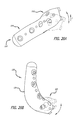
- the tibial base component 60 has an overall curved shape.
- the base component 60 includes a main body portion 62 and an arm portion 64 .
- the arm portion 64 of the base component 60 is shaped to position a link or absorber assembly approximately perpendicular to the tibial plateau to provide desired alignment across the joint.
- the arm portion 64 may be angled relative to the tibial plateau in order to provide some torque across the joint.
- the upper surface of the body is a curved convexly where the center of the body is thicker than the edges of the body.
- the base component 60 also includes rounded edges in order to minimize sharp edges that may otherwise cause damage to surrounding tissues when the component is coupled to the tibia.
- the main body portion 62 is generally narrow and includes a rounded first end 66 and a squared-off second end 68 .
- the second end 68 is configured to attach to mounts and devices for absorbing energy at a joint.
- the main body portion 62 is the portion of the base component 60 that contacts the tibia.
- the arm portion 64 is offset laterally from the bone (i.e., the arm portion does not contact the tibia). While the arm portion 64 of the base component 60 is offset from the bone, the base component defines a low-profile when mounted to the bone.
- the base component 60 also includes a plurality of openings 70 .
- the openings 70 are aligned along the center portion of the base component 60 .
- the openings 70 are positioned such that the screws contact the osteointegration area of the tibia.
- two openings 72 , 74 are provided on the arm portion 64 of the base component 60 .
- the two openings 72 , 74 are positioned such that the screws (as shown in FIGS. 18-19 ) will be mounted closer to the mounting location of the mounting member (not shown) at the end of the base component.
- the openings 70 , 72 , 74 are oriented to provide differing trajectories for fastening members that maximize pull forces thereby minimizing the possibility that the base component 60 is separated from the bone.
- the opening trajectories are oriented such that the hole trajectories are normal or approximately normal to the shear loading forces on the base component 10 .
- the two openings 72 , 74 on the arm portion 64 of the base component have differing trajectories, the posterior opening 72 orienting a fastening member at an upward trajectory, and the anterior opening 74 orienting a fastening member at a slightly upward trajectory.
- FIGS. 6-7 and 13-14 illustrate structure having five openings, it is contemplated that other embodiments of the base component may be have any number of openings. Additionally, the openings may be oriented such that fastening members will have different trajectories.
- the tibial base component 60 also includes a plurality of holes 76 that may be used during alignment of the base component 60 on the tibia and sized to receive structure such as a K-wire.
- the base component 60 may include a plurality of holes (not shown) to promote bone in-growth thereby improving base component stability.
- the inner surface facilitates the base component 60 absorbing and transferring load forces from the base component to the tibia.
- the inner surface 78 of the base component 60 may include one or more spikes or tabs.
- FIGS. 15A-B are cross-sectional views of the inner surface 78 of the tibial base component 60 .
- the inner surface 78 has an osteointegration coating applied to the top surface 80 and the edges 82 of the inner surface 78 .
- the osteointegration coating (not shown) is only applied to the inner surface.
- FIG. 15B illustrates a another embodiment where a portion of the osteointegration coating 84 on the inner surface 78 is over-contoured (i.e., extends above the plane of the inner surface 78 ).
- the over-contoured coating 84 surface is compressed when the tibial base component 60 is affixed to the bone, thereby preventing micro-motion of the base component.
- the over-contoured coating 84 also concentrates the compressive forces on the middle of the inner surface 78 .
- the tibial base component 60 has a generally low-profile when mounted to the bone.
- the base component 60 is mounted to the medial surface of the tibia in order to preserve critical anatomy such as, but not limited to, medial collateral ligaments while positioning the second end 68 of the base component as close to the pivot point of the tibia.
- the arm portion 64 of the base component 60 is also offset from the surface of the tibia to avoid critical structure while maintaining a low profile of the base component.
- the tibial base component 60 shown in FIGS. 13-17 is configured to be fixed to the medial surface of the left tibia. As those skilled in the art will appreciate, a mirror image of the base component 60 shown in FIGS. 13-17 would be fixable to the medial surface of the right tibia. Additionally, the base component may be configured to be fixed to the lateral surface of the left or right tibia. In another approach, the base component may be configured to be coupled to lateral surfaces of both the tibia and fibula. In yet another embodiment, base components may be fixed to both the lateral and medial surfaces of the left or right tibia.
- FIGS. 18-19 illustrate one embodiment of an extra-articular implantable mechanical energy absorbing system 100 that is coupled to the second ends 18 , 68 of the femoral and tibial base components 10 , 60 , respectively.
- the mechanical energy absorbing system 100 can function to reduce desired forces from a knee joint. It is also to be recognized that the placement of the bases on the bones is made such that further procedures, such as a TKA, can be conducted at the joint while leaving the bases in place but after removing the absorbing system. Additionally, the absorbing system can be replaced without having to replace the base components resulting in removal of all of the wear components.
- the base component may be made from a wide range of materials.
- the base components are made from metals and alloys such as, but not limited to, Titanium, stainless steel, Cobalt Chrome.
- the base components are made from thermoplastic materials such as, but not limited to, polyetheretherketones (PEEK).
- PEEK polyetheretherketones
- Various embodiments of the base components are rigid structures.
- FIGS. 20A-B illustrate a tibial base component 110 and a femoral base component 120 having partially flexible regions 112 , 122 for flexing and/or twisting.
- each base component 110 , 120 includes a rigid section 114 , 124 and the flexible region 112 , 122 .
- the rigid section 114 , 124 of the base components 110 , 120 are mountable to the bone and can include an osteointegration surface.
- the flexible region 112 , 122 of the base components 110 , 120 extends from the base and provides additional load bypass capabilities.
- the flexible regions 112 , 114 of the base components 110 , 120 apply a linear or nonlinear spring force when the flexible region is deflected.
- bases can incorporate one or more of the previously described features or can embody structure separate to itself.
- one or more of the bases can include adjustment structures.
- a base 130 can include two pieces 132 , 134 which are slideable with respect to each other.
- a top piece 132 can be formed of a material through which fastening members can be forceably inserted without originally including one or more through holes, whereas the bottom piece 134 can include previously machined through holes.
- the top piece 132 can be adjusted with respect to the bottom piece and the adjusted juxtapositional relationship can be set with the fasteners employed to attach the assembly to body anatomy. Accordingly, such alterations can translate into adjusting as desired the action of absorber components of an energy absorbing assembly.
- the materials be selected for the bases so that they define flexible structure intended to absorb forces. Such an approach is useful where the sub-structure of an energy absorbing device includes a defined fully loaded position so that further loads are transferred to the flexible bases.
- the base component can include structure which relies on surrounding anatomy for additional support.
- a base 160 can include structure extending to and overlaying a fibula 162 .
- a base assembly 170 can include multiple pieces attached to opposite sides of a bone and can further include a restraining cross-bar 172 extending from one of the multiple pieces to another.
- bases 190 can have simple through holes 192 ( FIGS. 29 and 32 ) for fastening members or such holes can include countersinks 194 ( FIG. 31 ). Additionally, the fastening holes can define screw head sockets 196 as shown in FIG. 30 . Moreover, the contemplated bases can embody various approaches for accomplishing connection to the bone such as by including spikes 198 ( FIGS. 29 and 32 ) or rotatable spurs 200 ( FIG. 30 ). Furthermore, the bases 190 can include small holes 202 such as those having a diameter of less than 1 mm for boney, interlocking in-growth ( FIG. 29 ).
- the base 210 can include a slotted region 212 for receiving corresponding structures.
- the holes 214 formed on a base 216 can be numbered or otherwise identified to assist a physician in selecting proper fastening members.
Landscapes
- Health & Medical Sciences (AREA)
- Life Sciences & Earth Sciences (AREA)
- Orthopedic Medicine & Surgery (AREA)
- Surgery (AREA)
- Animal Behavior & Ethology (AREA)
- Veterinary Medicine (AREA)
- Public Health (AREA)
- Engineering & Computer Science (AREA)
- Biomedical Technology (AREA)
- Heart & Thoracic Surgery (AREA)
- General Health & Medical Sciences (AREA)
- Molecular Biology (AREA)
- Medical Informatics (AREA)
- Nuclear Medicine, Radiotherapy & Molecular Imaging (AREA)
- Rehabilitation Therapy (AREA)
- Rheumatology (AREA)
- Cardiology (AREA)
- Oral & Maxillofacial Surgery (AREA)
- Transplantation (AREA)
- Vascular Medicine (AREA)
- Neurology (AREA)
- Prostheses (AREA)
Priority Applications (8)
| Application Number | Priority Date | Filing Date | Title |
|---|---|---|---|
| US12/112,415 US9655648B2 (en) | 2007-05-01 | 2008-04-30 | Femoral and tibial base components |
| US12/112,442 US10022154B2 (en) | 2007-05-01 | 2008-04-30 | Femoral and tibial base components |
| AU2009241768A AU2009241768B2 (en) | 2008-04-30 | 2009-04-30 | Femoral and tibial base components |
| JP2011507469A JP2011519303A (ja) | 2008-04-30 | 2009-04-30 | 大腿骨及び脛骨用基部構成要素 |
| EP09739244A EP2273940A2 (fr) | 2008-04-30 | 2009-04-30 | Composants servant de supports fémoraux et tibiaux |
| PCT/US2009/002714 WO2009134441A2 (fr) | 2007-05-01 | 2009-04-30 | Composants servant de supports fémoraux et tibiaux |
| CA2725420A CA2725420A1 (fr) | 2008-04-30 | 2009-04-30 | Composants servant de supports femoraux et tibiaux |
| US14/183,047 US9398957B2 (en) | 2007-05-01 | 2014-02-18 | Femoral and tibial bases |
Applications Claiming Priority (8)
| Application Number | Priority Date | Filing Date | Title |
|---|---|---|---|
| US11/743,097 US20080275567A1 (en) | 2007-05-01 | 2007-05-01 | Extra-Articular Implantable Mechanical Energy Absorbing Systems |
| US11/743,605 US10736746B2 (en) | 2007-05-01 | 2007-05-02 | Extra-articular implantable mechanical energy absorbing systems |
| US11/775,149 US7655041B2 (en) | 2007-05-01 | 2007-07-09 | Extra-articular implantable mechanical energy absorbing systems and implantation method |
| US11/775,145 US7678147B2 (en) | 2007-05-01 | 2007-07-09 | Extra-articular implantable mechanical energy absorbing systems and implantation method |
| US11/775,139 US7611540B2 (en) | 2007-05-01 | 2007-07-09 | Extra-articular implantable mechanical energy absorbing systems and implantation method |
| US4910808P | 2008-04-30 | 2008-04-30 | |
| US12/112,415 US9655648B2 (en) | 2007-05-01 | 2008-04-30 | Femoral and tibial base components |
| US12/112,442 US10022154B2 (en) | 2007-05-01 | 2008-04-30 | Femoral and tibial base components |
Related Parent Applications (1)
| Application Number | Title | Priority Date | Filing Date |
|---|---|---|---|
| US11/743,097 Continuation-In-Part US20080275567A1 (en) | 2007-05-01 | 2007-05-01 | Extra-Articular Implantable Mechanical Energy Absorbing Systems |
Related Child Applications (1)
| Application Number | Title | Priority Date | Filing Date |
|---|---|---|---|
| US12/755,335 Continuation-In-Part US20110245928A1 (en) | 2007-05-01 | 2010-04-06 | Femoral and Tibial Bases |
Publications (2)
| Publication Number | Publication Date |
|---|---|
| US20080275560A1 US20080275560A1 (en) | 2008-11-06 |
| US10022154B2 true US10022154B2 (en) | 2018-07-17 |
Family
ID=41056785
Family Applications (2)
| Application Number | Title | Priority Date | Filing Date |
|---|---|---|---|
| US12/112,442 Active 2030-01-03 US10022154B2 (en) | 2007-05-01 | 2008-04-30 | Femoral and tibial base components |
| US12/112,415 Active 2029-09-20 US9655648B2 (en) | 2007-05-01 | 2008-04-30 | Femoral and tibial base components |
Family Applications After (1)
| Application Number | Title | Priority Date | Filing Date |
|---|---|---|---|
| US12/112,415 Active 2029-09-20 US9655648B2 (en) | 2007-05-01 | 2008-04-30 | Femoral and tibial base components |
Country Status (2)
| Country | Link |
|---|---|
| US (2) | US10022154B2 (fr) |
| WO (1) | WO2009134441A2 (fr) |
Families Citing this family (32)
| Publication number | Priority date | Publication date | Assignee | Title |
|---|---|---|---|---|
| US20080275509A1 (en) * | 2007-05-01 | 2008-11-06 | Exploramed Nc4, Inc. | Mounts for implantable extra-articular systems |
| US20100137996A1 (en) | 2007-05-01 | 2010-06-03 | Moximed, Inc. | Femoral and tibial base components |
| US10022154B2 (en) | 2007-05-01 | 2018-07-17 | Moximed, Inc. | Femoral and tibial base components |
| US20110245928A1 (en) * | 2010-04-06 | 2011-10-06 | Moximed, Inc. | Femoral and Tibial Bases |
| US8894714B2 (en) | 2007-05-01 | 2014-11-25 | Moximed, Inc. | Unlinked implantable knee unloading device |
| EP2299918B1 (fr) * | 2008-04-30 | 2017-03-22 | Moximed, Inc. | Supports pour systèmes extra-articulaires implantables |
| WO2010111205A2 (fr) * | 2009-03-23 | 2010-09-30 | University Of Maryland, Baltimore | Plaques pour fracture spécifique du radius distal |
| US9861408B2 (en) * | 2009-08-27 | 2018-01-09 | The Foundry, Llc | Method and apparatus for treating canine cruciate ligament disease |
| US9668868B2 (en) | 2009-08-27 | 2017-06-06 | Cotera, Inc. | Apparatus and methods for treatment of patellofemoral conditions |
| US10349980B2 (en) | 2009-08-27 | 2019-07-16 | The Foundry, Llc | Method and apparatus for altering biomechanics of the shoulder |
| US9278004B2 (en) | 2009-08-27 | 2016-03-08 | Cotera, Inc. | Method and apparatus for altering biomechanics of the articular joints |
| CN116570353A (zh) * | 2009-08-27 | 2023-08-11 | 铸造有限责任公司 | 用于改变膝关节中髌骨与股骨之间的负载及治疗髋关节疾病的设备 |
| CA2772915C (fr) * | 2009-09-02 | 2017-09-19 | Skeletal Dynamics, Llc | Dispositif interne stabilisateur d'articulation, systeme et procede d'utilisation |
| US8679178B2 (en) * | 2009-10-20 | 2014-03-25 | Moximed, Inc. | Extra-articular implantable mechanical energy absorbing assemblies having two deflecting members and compliance member |
| US8523948B2 (en) * | 2009-10-20 | 2013-09-03 | Moximed, Inc. | Extra-articular implantable mechanical energy absorbing assemblies having a tension member, and methods |
| US20110112639A1 (en) * | 2009-11-06 | 2011-05-12 | Moximed, Inc. | Positioning Systems and Methods for Implanting an Energy Absorbing System |
| US8206452B2 (en) * | 2010-02-18 | 2012-06-26 | Biomet Manufacturing Corp. | Prosthetic device with damper |
| US9044270B2 (en) | 2011-03-29 | 2015-06-02 | Moximed, Inc. | Apparatus for controlling a load on a hip joint |
| JP2014525776A (ja) * | 2011-06-30 | 2014-10-02 | ロリオ,モーガン,パッカード | 脊椎プレート及びその使用方法 |
| US20130261670A1 (en) * | 2012-03-29 | 2013-10-03 | DePuy Synthes Products, LLC | Implant and associated instruments and methods |
| US20130325122A1 (en) | 2012-06-04 | 2013-12-05 | Moximed, Inc. | Low contact femoral and tibial bases |
| US9468466B1 (en) | 2012-08-24 | 2016-10-18 | Cotera, Inc. | Method and apparatus for altering biomechanics of the spine |
| ITVR20130013A1 (it) * | 2013-01-21 | 2014-07-22 | Tecres Spa | Dispositivo fissatore esterno per il trattamento di fratture ossee |
| US20140257501A1 (en) * | 2013-03-08 | 2014-09-11 | Moximed, Inc. | Joint Energy Absorbing System and Method of Use |
| CA2905124C (fr) | 2013-03-11 | 2021-10-26 | Embark Enterprises, Inc. | Systeme de stabilisation de grasset pour quadrupede |
| WO2014165025A1 (fr) * | 2013-03-13 | 2014-10-09 | Moximed, Inc. | Ensembles extra-articulaires implantables absorbant l'énergie mécanique, et procédés correspondants |
| WO2014150786A1 (fr) * | 2013-03-15 | 2014-09-25 | Moximed, Inc. | Approche et moyen d'implantation pour un système d'absorption d'énergie |
| US9820786B2 (en) * | 2014-01-30 | 2017-11-21 | Rahul Vaidya | Knee hinge fixation apparatus and method for application thereof |
| US20150282848A1 (en) * | 2014-01-30 | 2015-10-08 | Rahul Vaidya | Knee brace fixation apparatus and method for application thereof |
| US20170196678A1 (en) * | 2014-09-23 | 2017-07-13 | University Of Virginia Patent Foundation | Tendon and ligament fixation device and method of use |
| KR101681556B1 (ko) * | 2014-12-03 | 2016-12-01 | 백혜선 | 폐쇄성 원위 대퇴골 절골술용 고정 기구 |
| JP2024532849A (ja) * | 2021-08-17 | 2024-09-10 | ペレス エドワード | 骨固定装置、システム、および方法 |
Citations (149)
| Publication number | Priority date | Publication date | Assignee | Title |
|---|---|---|---|---|
| US2632440A (en) | 1947-12-17 | 1953-03-24 | John M Hauser | Leg brace joint and lock |
| US2877033A (en) | 1956-03-16 | 1959-03-10 | Dreher Mfg Company | Artificial joint |
| US3242922A (en) | 1963-06-25 | 1966-03-29 | Charles B Thomas | Internal spinal fixation means |
| US3648294A (en) | 1969-02-08 | 1972-03-14 | Esfandiar Shahrestani | Endoprostheses, especially for hip joints |
| US3681786A (en) | 1970-07-13 | 1972-08-08 | Medical Eng Corp | Solid human prosthesis of varying consistency |
| US3779654A (en) | 1971-08-06 | 1973-12-18 | R Horne | Artificial joint |
| US3875594A (en) | 1973-08-27 | 1975-04-08 | Dow Corning | Surgically implantable prosthetic joint having load distributing flexible hinge |
| US3902482A (en) | 1974-05-21 | 1975-09-02 | George A Taylor | Mechanical joint for an orthopedic brace or prosthesis |
| US3988783A (en) | 1976-01-21 | 1976-11-02 | Richards Manufacturing Company, Inc. | Prosthetic collateral ligament |
| US4187841A (en) | 1978-07-07 | 1980-02-12 | Knutson Richard A | Bone compression or distraction device |
| US4246660A (en) | 1978-12-26 | 1981-01-27 | Queen's University At Kingston | Artificial ligament |
| US4308863A (en) | 1979-10-18 | 1982-01-05 | Ace Orthopedic Manufacturing, Inc. | External fixation device |
| US4353361A (en) | 1980-08-25 | 1982-10-12 | Foster Robert W | Orthotic/prosthetic joint |
| US4501266A (en) | 1983-03-04 | 1985-02-26 | Biomet, Inc. | Knee distraction device |
| US4570625A (en) | 1981-08-06 | 1986-02-18 | National Research Development Corporation | Apparatus for external fixation of bone fractures |
| US4576158A (en) | 1983-01-28 | 1986-03-18 | Region Wallone | Method for determining the stability of an orthopedic device composed of an external fixation bar during setting of bone fractures |
| US4621627A (en) | 1984-12-18 | 1986-11-11 | Orthofix S.R.L. | External axial fixation device |
| US4637382A (en) | 1982-04-27 | 1987-01-20 | Brigham & Women's Hospital | Motion-guiding load-bearing external linkage for the knee |
| US4696293A (en) | 1982-09-30 | 1987-09-29 | Ciullo Jerome V | Hinged external fixator |
| US4776851A (en) | 1986-07-23 | 1988-10-11 | Bruchman William C | Mechanical ligament |
| US4846842A (en) | 1987-06-25 | 1989-07-11 | Connolly & Mcmaster | Body joint rotation support device |
| US4871367A (en) | 1987-09-03 | 1989-10-03 | Sutter Biomedical Corporation | Surgically implanted prosthesis |
| GB2223406A (en) | 1988-08-01 | 1990-04-11 | Univ Bristol | External fixator device |
| US4942875A (en) | 1986-03-03 | 1990-07-24 | American Cyanamid Company | Surgical repair device having absorbable and nonabsorbable components |
| EP0383419A1 (fr) | 1989-02-15 | 1990-08-22 | Johnson & Johnson Professional Products GmbH | Fixateur orthopédique |
| US4988349A (en) | 1987-01-21 | 1991-01-29 | Orthofix S.R.L. | Device for osteosynthesis |
| US5002574A (en) | 1989-08-18 | 1991-03-26 | Minnesota Mining And Manufacturing Co. | Tensioning means for prosthetic devices |
| US5011497A (en) | 1987-10-29 | 1991-04-30 | Atos Medical Ab | Joint prosthesis |
| US5019077A (en) | 1989-03-17 | 1991-05-28 | Orthofix S.R.L. | External splint |
| US5026372A (en) | 1987-11-05 | 1991-06-25 | Robert Sturtzkopf | Fixation device for the external adjusting of bone fragments |
| US5041112A (en) | 1989-11-30 | 1991-08-20 | Citieffe S.R.L. | External splint for the treatment of fractures of the long bones of limbs |
| US5100403A (en) | 1990-06-08 | 1992-03-31 | Smith & Nephew Richards, Inc. | Dynamic elbow support |
| US5103811A (en) | 1990-07-09 | 1992-04-14 | Crupi Jr Theodore P | Body part or joint brace |
| US5121742A (en) | 1989-10-27 | 1992-06-16 | Baylor College Of Medicine | Lower extremity orthotic device |
| GB2250919A (en) | 1989-11-14 | 1992-06-24 | Lazar Lvovich Rodnyansky | Endoapparatus for restoration of hip joint |
| US5152280A (en) | 1989-01-04 | 1992-10-06 | Confida S.A.S | Bone support device |
| WO1994006364A1 (fr) | 1992-09-15 | 1994-03-31 | Dynastab Limited Partnership | Stabilisateur de compensation dynamique |
| US5352190A (en) | 1990-03-16 | 1994-10-04 | Q-Motus, Inc. | Knee brace |
| US5375823A (en) | 1992-06-25 | 1994-12-27 | Societe Psi | Application of an improved damper to an intervertebral stabilization device |
| US5405347A (en) | 1993-02-12 | 1995-04-11 | Zimmer, Inc. | Adjustable connector for external fixation rods |
| US5415661A (en) | 1993-03-24 | 1995-05-16 | University Of Miami | Implantable spinal assist device |
| WO1996019944A1 (fr) | 1994-12-23 | 1996-07-04 | Danieli Giorgio S | Dispositif de soutien des articulations |
| US5540688A (en) | 1991-05-30 | 1996-07-30 | Societe "Psi" | Intervertebral stabilization device incorporating dampers |
| US5575819A (en) | 1986-09-19 | 1996-11-19 | Imperial College Of Science And Technology | Artificial ligaments |
| US5578038A (en) | 1992-06-18 | 1996-11-26 | Slocum; D. Barclay | Jig for use in osteotomies |
| US5624440A (en) | 1996-01-11 | 1997-04-29 | Huebner; Randall J. | Compact small bone fixator |
| US5662648A (en) | 1993-03-15 | 1997-09-02 | Orthofix S.R.L. | Method and apparatus for the external setting of fractures |
| US5662650A (en) | 1995-05-12 | 1997-09-02 | Electro-Biology, Inc. | Method and apparatus for external fixation of large bones |
| US5681313A (en) | 1995-02-06 | 1997-10-28 | Karl Leibinger Medizintechnik Gmbh & Co. Kg | Device for the extension of bones |
| US5695496A (en) | 1995-01-17 | 1997-12-09 | Smith & Nephew Inc. | Method of measuring bone strain to detect fracture consolidation |
| US5803924A (en) | 1993-08-05 | 1998-09-08 | Hi-Shear Fastners Europe Limited | External fixator |
| US5873843A (en) | 1994-02-18 | 1999-02-23 | Btg International Limited | Assessing the state of union in a bone fracture |
| US5928234A (en) | 1997-10-10 | 1999-07-27 | Manspeizer; Sheldon | External fixture for tracking motion of a joint |
| US5976136A (en) | 1998-05-11 | 1999-11-02 | Electro Biology, Inc. | Method and apparatus for external bone fixator |
| US5976125A (en) | 1995-08-29 | 1999-11-02 | The Cleveland Clinic Foundation | External distractor/fixator for the management of fractures and dislocations of interphalangeal joints |
| EP0953317A1 (fr) | 1998-04-30 | 1999-11-03 | Fred Zacouto | Implant squelettique |
| US5993449A (en) | 1995-11-30 | 1999-11-30 | Synthes (Usa) | Bone-fixing device |
| US6036691A (en) | 1993-12-14 | 2000-03-14 | Richardson; James Bruce | External orthopedic fixator with patient-operated mechanism |
| DE19855254A1 (de) | 1998-11-30 | 2000-06-08 | Richard Hans Albert | Vorrichtung zur Retention und Protektion von beschädigten Knochen |
| US6113637A (en) | 1998-10-22 | 2000-09-05 | Sofamor Danek Holdings, Inc. | Artificial intervertebral joint permitting translational and rotational motion |
| US6162223A (en) | 1999-04-09 | 2000-12-19 | Smith & Nephew, Inc. | Dynamic wrist fixation apparatus for early joint motion in distal radius fractures |
| US6176860B1 (en) | 1995-07-24 | 2001-01-23 | Hadasit Medical Research Services & Development Company, Ltd. | Orthopaedic fixator |
| US6264696B1 (en) | 1999-01-04 | 2001-07-24 | Aesculap | Tibial knee prosthesis comprising a ball joint with double inserts |
| US6277124B1 (en) | 1999-10-27 | 2001-08-21 | Synthes (Usa) | Method and apparatus for ratcheting adjustment of bone segments |
| US20010020143A1 (en) | 1997-03-24 | 2001-09-06 | Stark John G. | Instrumented accelerometers for patient monitoring |
| US6355037B1 (en) | 2000-12-05 | 2002-03-12 | Smith & Nephew, Inc. | Apparatus and method of external skeletal support allowing for internal-external rotation |
| US20020045901A1 (en) * | 1999-03-09 | 2002-04-18 | Michael Wagner | Bone plate |
| US6409729B1 (en) | 1998-05-19 | 2002-06-25 | Synthes (Usa) | Clamp assembly for an external fixation system |
| US20020095154A1 (en) | 2000-04-04 | 2002-07-18 | Atkinson Robert E. | Devices and methods for the treatment of spinal disorders |
| US6482232B1 (en) | 1997-07-23 | 2002-11-19 | Biomet, Inc. | Apparatus and method for tibial fixation of soft tissue |
| US6494914B2 (en) | 2000-12-05 | 2002-12-17 | Biomet, Inc. | Unicondylar femoral prosthesis and instruments |
| US20030040749A1 (en) * | 2001-08-24 | 2003-02-27 | Grabowski John J. | Bone fixation device |
| US6527733B1 (en) | 2000-02-22 | 2003-03-04 | Dj Orthopedics, Llc | Hinge assembly for an orthopedic knee brace and knee brace incorporating the hinge assembly |
| US6540708B1 (en) * | 2000-02-18 | 2003-04-01 | Sheldon Manspeizer | Polycentric joint for internal and external knee brace |
| US6572653B1 (en) | 2001-12-07 | 2003-06-03 | Rush E. Simonson | Vertebral implant adapted for posterior insertion |
| US6599322B1 (en) | 2001-01-25 | 2003-07-29 | Tecomet, Inc. | Method for producing undercut micro recesses in a surface, a surgical implant made thereby, and method for fixing an implant to bone |
| US6620332B2 (en) | 2001-01-25 | 2003-09-16 | Tecomet, Inc. | Method for making a mesh-and-plate surgical implant |
| US6623486B1 (en) | 1999-09-13 | 2003-09-23 | Synthes (U.S.A.) | bone plating system |
| US20030216809A1 (en) | 2000-10-24 | 2003-11-20 | Ferguson Joe W. | Method for securing soft tissue to an artificial prosthesis |
| US6663631B2 (en) | 2000-12-01 | 2003-12-16 | Charles A. Kuntz | Method and device to correct instability of hinge joints |
| WO2004019831A2 (fr) | 2002-08-12 | 2004-03-11 | Marc Franke | Articulation artificielle |
| WO2004024037A1 (fr) | 2002-09-10 | 2004-03-25 | Ferree Bret A | Protheses discales et articulaires d'absorption de chocs |
| US20040102778A1 (en) * | 2002-11-19 | 2004-05-27 | Huebner Randall J. | Adjustable bone plates |
| US6752831B2 (en) | 2000-12-08 | 2004-06-22 | Osteotech, Inc. | Biocompatible osteogenic band for repair of spinal disorders |
| US20040260302A1 (en) | 2003-06-19 | 2004-12-23 | Sheldon Manspeizer | Internal brace for distraction arthroplasty |
| US20040267179A1 (en) | 2003-06-30 | 2004-12-30 | Max Lerman | Knee unloading orthotic device and method |
| US20050085815A1 (en) | 2003-10-17 | 2005-04-21 | Biedermann Motech Gmbh | Rod-shaped implant element for application in spine surgery or trauma surgery, stabilization apparatus comprising said rod-shaped implant element, and production method for the rod-shaped implant element |
| US20050119744A1 (en) | 2000-01-11 | 2005-06-02 | Regeneration Technologies, Inc. | Soft and calcified tissue implants |
| US20050154390A1 (en) | 2003-11-07 | 2005-07-14 | Lutz Biedermann | Stabilization device for bones comprising a spring element and manufacturing method for said spring element |
| US20050192674A1 (en) | 1999-10-08 | 2005-09-01 | Ferree Bret A. | Prosthetic joints with contained compressible resilient members |
| US6966910B2 (en) | 2002-04-05 | 2005-11-22 | Stephen Ritland | Dynamic fixation device and method of use |
| US20050261680A1 (en) | 2001-03-28 | 2005-11-24 | Imperial College Innovations Ltd. | Bone fixated, articulated joint load control device |
| US6972020B1 (en) | 2001-06-01 | 2005-12-06 | New York University | Multi-directional internal distraction osteogenesis device |
| US7018418B2 (en) | 2001-01-25 | 2006-03-28 | Tecomet, Inc. | Textured surface having undercut micro recesses in a surface |
| US7029475B2 (en) | 2003-05-02 | 2006-04-18 | Yale University | Spinal stabilization method |
| US20060178744A1 (en) | 2005-02-04 | 2006-08-10 | Spinalmotion, Inc. | Intervertebral prosthetic disc with shock absorption |
| WO2006110578A2 (fr) | 2005-04-08 | 2006-10-19 | Paradigm Spine, Llc. | Dispositifs de stabilisation vertebrale et lombo-sacree interepineux et procedes d'utilisation correspondants |
| US7141073B2 (en) | 1993-11-01 | 2006-11-28 | Biomet, Inc. | Compliant fixation of external prosthesis |
| US20070043356A1 (en) | 2005-07-26 | 2007-02-22 | Timm Jens P | Dynamic spine stabilization device with travel-limiting functionality |
| US7188626B2 (en) | 1999-10-20 | 2007-03-13 | Warsaw Orthopedic, Inc. | Instruments and methods for stabilization of bony structures |
| US7201728B2 (en) | 2002-06-28 | 2007-04-10 | Shane Sterling | Anatomically designed orthopedic knee brace |
| WO2007056645A2 (fr) | 2005-11-02 | 2007-05-18 | Zimmer Technology, Inc. | Implant d'écartement d'articulation |
| US7235102B2 (en) | 2002-05-10 | 2007-06-26 | Ferree Bret A | Prosthetic components with contained compressible resilient members |
| US7241298B2 (en) | 2003-01-31 | 2007-07-10 | Howmedica Osteonics Corp. | Universal alignment guide |
| US20070161993A1 (en) | 2005-09-27 | 2007-07-12 | Lowery Gary L | Interspinous vertebral stabilization devices |
| US20070168036A1 (en) | 2003-10-23 | 2007-07-19 | Trans1 Inc. | Spinal motion preservation assemblies |
| US20070168033A1 (en) | 2003-08-01 | 2007-07-19 | Kim Daniel H | Prosthetic intervertebral discs having substantially rigid end plates and fibers between those end plates |
| US7247157B2 (en) | 2003-01-23 | 2007-07-24 | Stryker Trauma Gmbh | Implant for osteosynthesis |
| US7252670B2 (en) | 1999-04-16 | 2007-08-07 | Sdgi Holdings, Inc. | Multi-axial bone anchor system |
| WO2007090017A1 (fr) | 2006-01-27 | 2007-08-09 | Warsaw Orthopedic, Inc. | Implants intervertebraux et procedes d'utilisation |
| WO2007090015A1 (fr) | 2006-01-27 | 2007-08-09 | Warsaw Orthopedic, Inc. | Tiges vertébrales et méthodes d'utilisation |
| WO2007090009A1 (fr) | 2006-01-27 | 2007-08-09 | Warsaw Orthopedic, Inc. | Dispositifs interepineux et procedes d'utilisation |
| US20070198088A1 (en) | 2003-10-17 | 2007-08-23 | Lutz Biedermann | Flexible implant |
| US20070198091A1 (en) | 2005-12-06 | 2007-08-23 | Boyer Michael L | Facet joint prosthesis |
| US7261739B2 (en) | 2001-10-18 | 2007-08-28 | Spinecore, Inc. | Intervertebral spacer device having arch shaped spring element |
| US7273481B2 (en) | 2002-10-28 | 2007-09-25 | Blackstone Medical, Inc. | Bone plate assembly provided with screw locking mechanisms |
| WO2007106962A1 (fr) | 2006-03-17 | 2007-09-27 | Gm Dos Reis Jr Indústria E Comércio De Equipamentos Médicos | Plaque pour os |
| WO2007109436A2 (fr) | 2006-03-20 | 2007-09-27 | Depuy Products, Inc. | Système de stabilisation d'os incluant un élément de fixation fileté multi-directionnel |
| WO2007109417A2 (fr) | 2005-03-17 | 2007-09-27 | Depuy Products, Inc. | Systeme de plaque de fixation de fracture modulaire |
| US7276070B2 (en) | 2003-06-11 | 2007-10-02 | Mueckter Helmut | Osteosynthesis plate or comparable implant plus ball socket |
| WO2007114769A1 (fr) | 2006-04-04 | 2007-10-11 | Gs Development Ab | Dispositif prothetique pour articulations |
| US7282065B2 (en) | 2004-04-09 | 2007-10-16 | X-Spine Systems, Inc. | Disk augmentation system and method |
| EP1682020B1 (fr) | 2003-09-08 | 2007-10-17 | Synthes GmbH | Dispositif de fixation osseuse |
| WO2007117571A2 (fr) | 2006-04-06 | 2007-10-18 | Lotus Medical, Llc | UTILISATION de la compression active pour favoriser la guerison osseuse |
| US20070244483A9 (en) | 2005-05-10 | 2007-10-18 | Winslow Charles J | Inter-cervical facet implant with implantation tool |
| US20070244488A1 (en) | 2006-03-03 | 2007-10-18 | Robert Metzger | Tensor for use in surgical navigation |
| EP1847229A2 (fr) | 1997-02-11 | 2007-10-24 | Warsaw Orthopedic, Inc. | Système de plaquage squelettique à verrou unique |
| EP1847228A1 (fr) | 2006-04-21 | 2007-10-24 | DePuy Products, Inc. | Plaque de fixation dotée de trous multifonction |
| US7288094B2 (en) | 2005-06-10 | 2007-10-30 | Sdgi Holdings, Inc. | System and method for retaining screws relative to a vertebral plate |
| US7288095B2 (en) | 2004-08-12 | 2007-10-30 | Atlas Spine, Inc. | Bone plate with screw lock |
| US7291150B2 (en) | 1999-12-01 | 2007-11-06 | Sdgi Holdings, Inc. | Intervertebral stabilising device |
| US7306605B2 (en) | 2003-10-02 | 2007-12-11 | Zimmer Spine, Inc. | Anterior cervical plate |
| US20070288014A1 (en) | 2006-06-06 | 2007-12-13 | Shadduck John H | Spine treatment devices and methods |
| WO2008006098A2 (fr) | 2006-07-07 | 2008-01-10 | Warsaw Orthopedic, Inc. | Dispositions dynamiques pour stabilisation spinale |
| US20080015591A1 (en) * | 2006-07-13 | 2008-01-17 | Castaneda Javier E | Threaded Guide for an Orthopedic Fixation Plate |
| US20080015593A1 (en) | 2005-03-24 | 2008-01-17 | Joachim Pfefferle | Bone plate |
| US20080015592A1 (en) | 2006-06-28 | 2008-01-17 | Depuy Products, Inc. | CAM/compression lock plate |
| US7322984B2 (en) | 2005-01-06 | 2008-01-29 | Spinal, Llc | Spinal plate with internal screw locks |
| US7322983B2 (en) | 2002-02-12 | 2008-01-29 | Ebi, L.P. | Self-locking bone screw and implant |
| EP1005290B1 (fr) | 1997-07-29 | 2008-02-13 | DePuy Spine, Inc. | Plaque d'immobilisation pluriaxiale |
| US20080071375A1 (en) | 2005-10-10 | 2008-03-20 | Carver Donna J | Artificial spinal disc replacement system and method |
| US20080071373A1 (en) | 2004-01-30 | 2008-03-20 | Molz Fred J | Orthopedic distraction implants and techniques |
| US7361196B2 (en) | 2005-02-22 | 2008-04-22 | Stryker Spine | Apparatus and method for dynamic vertebral stabilization |
| US20080097441A1 (en) | 2004-10-20 | 2008-04-24 | Stanley Kyle Hayes | Systems and methods for posterior dynamic stabilization of the spine |
| EP1468655B1 (fr) | 2003-03-26 | 2008-05-21 | Precimed S.A. | Plaque d'ostéosynthèse à bloquer |
| US20080132954A1 (en) | 2005-05-02 | 2008-06-05 | Kinetic Spine Technologies, Inc. | Spinal stabilisation implant |
| US20080154378A1 (en) | 2006-12-22 | 2008-06-26 | Warsaw Orthopedic, Inc. | Bone implant having engineered surfaces |
| US20080275560A1 (en) | 2007-05-01 | 2008-11-06 | Exploramed Nc4, Inc. | Femoral and tibial base components |
| WO2008137487A1 (fr) | 2007-05-01 | 2008-11-13 | Exploramed Nc4, Inc. | Systèmes d'absorption d'énergie mécanique implantables extra-articulaires |
Family Cites Families (65)
| Publication number | Priority date | Publication date | Assignee | Title |
|---|---|---|---|---|
| DE1491233C3 (de) | 1964-10-05 | 1975-05-15 | Fa. Wilhelm Julius Teufel, 7000 Stuttgart | Kniegelenk'für Beinprothesen |
| SU578063A1 (ru) | 1971-05-20 | 1977-10-30 | Seppo Arnold | Ортопедический эндоаппарат дл восстановлени тазобедренного сустава |
| US3990116A (en) | 1974-10-17 | 1976-11-09 | Fixel Irving E | Pretensioned prosthetic device for skeletal joints |
| US4054955A (en) | 1976-01-29 | 1977-10-25 | Arnold Ivanovich Seppo | Orthopaedic endoapparatus designed to grow a new live shoulder and hip joint, to reconstruct a deformed joint or to restore a pathologically dysplastic and congenitally luxated joint |
| SU578957A1 (ru) | 1976-03-30 | 1977-11-05 | Pozdnikin Yurij | Способ реконструкции вертлужной впадины при дисплазии тазобедренного сустава |
| SU624613A1 (ru) | 1977-05-10 | 1978-09-25 | Tikhonenkov Egor S | Способ лечени врожденного вывиха бедра |
| SU640740A1 (ru) | 1977-07-12 | 1979-01-05 | Предприятие П/Я В-2769 | Устройство дл разработки подвижности в суставах нижних конечностей |
| SU719612A1 (ru) | 1977-10-28 | 1980-03-05 | Tikhonenkov Egor S | Способ углублени вертлужной впадины |
| SU704605A1 (ru) | 1978-03-14 | 1979-12-25 | Е. С. Тихоненков и С. . И. Федоров | Способ фиксации фрагментов бедренной кости после межвертельной и подвертельной коррегирующей остеотомии |
| SU741872A1 (ru) | 1978-05-04 | 1980-06-25 | за вители | Шина дл лечени врожденного вывиха бедра |
| GB2084468B (en) * | 1980-09-25 | 1984-06-06 | South African Inventions | Surgical implant |
| SU1699441A1 (ru) | 1981-07-08 | 1991-12-23 | Предприятие П/Я Г-4778 | Эндоаппарат дл восстановлени тазобедренного сустава |
| CA1205601A (fr) | 1982-09-10 | 1986-06-10 | Carl W. Bolton | Prothese de remplacement de tissus elastiques portant une charge et methode de production |
| JPS59131349A (ja) | 1982-09-10 | 1984-07-28 | ダブリユ・エル・ゴア・アンド・アソシエイツ,インコ−ポレイテイド | 引張り荷重支持組織用補綴材 |
| SU1251889A1 (ru) | 1984-01-27 | 1986-08-23 | Ленинградский Ордена Трудового Красного Знамени Научно-Исследовательский Детский Ортопедический Институт Им.Г.И.Турнера | Устройство дл динамической разгрузки тазобедренного сустава |
| SU1186204A1 (ru) | 1984-05-28 | 1985-10-23 | Московский Ордена Ленина И Ордена Октябрьской Революции Авиационный Институт Им.Серго Орджоникидзе | Устройство дл хирургического лечени повреждений тазобедренного сустава |
| US4863475A (en) | 1984-08-31 | 1989-09-05 | Zimmer, Inc. | Implant and method for production thereof |
| SU1316666A1 (ru) | 1984-09-27 | 1987-06-15 | В. В. Василенкайтис | Устройство В.В.Василенкайтиса дл разгрузки сустава |
| US4769011A (en) | 1985-03-28 | 1988-09-06 | Interpore International, Inc. | Syringe apparatus and method for the surgical implantation of granular substances |
| US4759765A (en) | 1986-03-17 | 1988-07-26 | Minnesota Mining And Manufacturing Company | Tissue augmentation device |
| US5225858A (en) * | 1987-06-01 | 1993-07-06 | Valdemar Portney | Multifocal ophthalmic lens |
| SU1588404A1 (ru) | 1988-06-12 | 1990-08-30 | Тартуский государственный университет | Устройство дл функциональной разгрузки тазобедренного сустава при переломах вертлужной впадины |
| US4959065A (en) | 1989-07-14 | 1990-09-25 | Techmedica, Inc. | Bone plate with positioning member |
| US4923471A (en) | 1989-10-17 | 1990-05-08 | Timesh, Inc. | Bone fracture reduction and fixation devices with identity tags |
| SE465202B (sv) | 1989-10-31 | 1991-08-12 | Leif Lindh | Led, foeretraedesvis foer en ortos, samt anvaendning av leden |
| SU1769868A1 (ru) | 1990-03-05 | 1992-10-23 | Le Ni Detskij Ortoped | Cпocoб лeчehия пocлeдctbий poдoboй tpabmы плeчeboгo cплetehия |
| US5234435A (en) | 1991-03-08 | 1993-08-10 | Seagrave Jr Richard A | Surgical method and apparatus |
| US5318567A (en) | 1991-07-02 | 1994-06-07 | Olivier Vichard | Screw-on plate for treatment of fractures of the odontoid apophysis |
| JP3683909B2 (ja) | 1993-10-08 | 2005-08-17 | ロゴジンスキ,チェーム | 脊椎の状態を処置する装置 |
| JP2532346B2 (ja) | 1993-10-12 | 1996-09-11 | 良二 城 | 体外式人工関節 |
| US5601553A (en) | 1994-10-03 | 1997-02-11 | Synthes (U.S.A.) | Locking plate and bone screw |
| RU2085148C1 (ru) | 1994-12-02 | 1997-07-27 | Научно-производственное внедренческое малое предприятие "Медилар" | Эндоаппарат для восстановления тазобедренного сустава |
| SE510125C2 (sv) | 1996-01-22 | 1999-04-19 | Handevelop Ab | Ledersättningsanordning |
| US6835207B2 (en) | 1996-07-22 | 2004-12-28 | Fred Zacouto | Skeletal implant |
| IT1287564B1 (it) | 1996-09-04 | 1998-08-06 | Maurizio Carta | Procedimento per la produzione di placche per osteosintesi a spessore variabile. |
| CA2523814C (fr) | 1997-02-11 | 2007-02-06 | Gary Karlin Michelson | Systeme pour poser des plaques d'osteosynthese squelettiques |
| US5984925A (en) | 1997-07-30 | 1999-11-16 | Cross Medical Products, Inc. | Longitudinally adjustable bone plates and method for use thereof |
| JPH1189860A (ja) | 1997-09-18 | 1999-04-06 | Senko Medical Instr Mfg Co Ltd | 人工靭帯 |
| US6197030B1 (en) | 1997-12-30 | 2001-03-06 | Christopher J. Pham | Elastic loaded retractable pin device for cranial bone attachment |
| US6045551A (en) | 1998-02-06 | 2000-04-04 | Bonutti; Peter M. | Bone suture |
| US6221075B1 (en) | 1998-03-06 | 2001-04-24 | Bionx Implants Oy | Bioabsorbable, deformable fixation plate |
| JP4278018B2 (ja) | 1999-11-19 | 2009-06-10 | 直秀 富田 | 膝関節徐荷器具 |
| US6401329B1 (en) * | 1999-12-21 | 2002-06-11 | Vishay Dale Electronics, Inc. | Method for making overlay surface mount resistor |
| US6692498B1 (en) | 2000-11-27 | 2004-02-17 | Linvatec Corporation | Bioabsorbable, osteopromoting fixation plate |
| FR2823096B1 (fr) | 2001-04-06 | 2004-03-19 | Materiel Orthopedique En Abreg | Plaque pour dispositif d'osteosynthese des vertebres l5 et s1, dispositif d'osteosynthese incluant une telle plaque, et instrument pour la pose d'une telle plaque |
| EP1404225A4 (fr) * | 2001-06-04 | 2009-09-16 | Warsaw Orthopedic Inc | Systeme a plaque cervicale anterieure munie de moyens d'ancrage en prise avec les corps de vertebres, plaque de connexion et procede de mise en place y relatif |
| FR2829920B1 (fr) | 2001-09-26 | 2004-05-28 | Newdeal Sa | Plaque de fixation des os d'une articulation, en particulier d'articulation metatarso-phalangienne |
| US7235077B1 (en) | 2001-11-09 | 2007-06-26 | Board Of Regents Of The University And Community College System Of Nevada On Behalf Of The University Of Nevada, Reno | Bone fixation device and method |
| US7238203B2 (en) | 2001-12-12 | 2007-07-03 | Vita Special Purpose Corporation | Bioactive spinal implants and method of manufacture thereof |
| RU2217105C2 (ru) | 2002-01-21 | 2003-11-27 | Федеральное государственное унитарное предприятие "Красноярский машиностроительный завод" | Эндоаппарат для восстановления тазобедренного сустава |
| US6679921B2 (en) | 2002-01-28 | 2004-01-20 | Robert Grubbs | Shuttle lock prosthetic connector |
| BR0313499A (pt) | 2002-08-15 | 2005-07-05 | David Gerber | Disco intervertebral |
| GB0219758D0 (en) | 2002-08-24 | 2002-10-02 | Grampian Univ Hospitals | Device |
| RU2241400C2 (ru) | 2002-09-23 | 2004-12-10 | Малахов Олег Алексеевич | Аппарат для декомпрессии тазобедренного сустава |
| US8105388B2 (en) | 2002-10-24 | 2012-01-31 | Biomet Manufacturing Corp. | Method and apparatus for wrist arthroplasty |
| US7285134B2 (en) | 2003-10-22 | 2007-10-23 | Warsaw Orthopedic, Inc. | Vertebral body replacement implant |
| US20070053963A1 (en) | 2004-01-13 | 2007-03-08 | Hotchkiss Robert N | Drug delivery to a joint |
| AU2005274013A1 (en) | 2004-08-09 | 2006-02-23 | Innovative Spinal Technologies | System and method for dynamic skeletal stabilization |
| US8162985B2 (en) | 2004-10-20 | 2012-04-24 | The Board Of Trustees Of The Leland Stanford Junior University | Systems and methods for posterior dynamic stabilization of the spine |
| JP2008518658A (ja) | 2004-10-28 | 2008-06-05 | アクシアル・バイオテック・インコーポレーテッド | 凹状の脊柱側弯症を膨張させる装置及び方法 |
| US20060241608A1 (en) | 2005-03-31 | 2006-10-26 | Mark Myerson | Plate for fusion of the metatarso-phalangeal joint |
| EP1770302A1 (fr) | 2005-09-30 | 2007-04-04 | Acandis GmbH & Co. KG | Procédé d'amortissement et dispositif correspondant |
| JP4439465B2 (ja) | 2005-12-21 | 2010-03-24 | 国立大学法人 新潟大学 | 関節免荷具検査装置 |
| JP2007170969A (ja) | 2005-12-21 | 2007-07-05 | Niigata Univ | 関節免荷具検査装置 |
| JP4591968B2 (ja) | 2005-12-21 | 2010-12-01 | 国立大学法人 新潟大学 | 股関節免荷具 |
-
2008
- 2008-04-30 US US12/112,442 patent/US10022154B2/en active Active
- 2008-04-30 US US12/112,415 patent/US9655648B2/en active Active
-
2009
- 2009-04-30 WO PCT/US2009/002714 patent/WO2009134441A2/fr not_active Ceased
Patent Citations (155)
| Publication number | Priority date | Publication date | Assignee | Title |
|---|---|---|---|---|
| US2632440A (en) | 1947-12-17 | 1953-03-24 | John M Hauser | Leg brace joint and lock |
| US2877033A (en) | 1956-03-16 | 1959-03-10 | Dreher Mfg Company | Artificial joint |
| US3242922A (en) | 1963-06-25 | 1966-03-29 | Charles B Thomas | Internal spinal fixation means |
| US3648294A (en) | 1969-02-08 | 1972-03-14 | Esfandiar Shahrestani | Endoprostheses, especially for hip joints |
| US3681786A (en) | 1970-07-13 | 1972-08-08 | Medical Eng Corp | Solid human prosthesis of varying consistency |
| US3779654A (en) | 1971-08-06 | 1973-12-18 | R Horne | Artificial joint |
| US3875594A (en) | 1973-08-27 | 1975-04-08 | Dow Corning | Surgically implantable prosthetic joint having load distributing flexible hinge |
| US3902482A (en) | 1974-05-21 | 1975-09-02 | George A Taylor | Mechanical joint for an orthopedic brace or prosthesis |
| US3988783A (en) | 1976-01-21 | 1976-11-02 | Richards Manufacturing Company, Inc. | Prosthetic collateral ligament |
| US4187841A (en) | 1978-07-07 | 1980-02-12 | Knutson Richard A | Bone compression or distraction device |
| US4246660A (en) | 1978-12-26 | 1981-01-27 | Queen's University At Kingston | Artificial ligament |
| US4308863A (en) | 1979-10-18 | 1982-01-05 | Ace Orthopedic Manufacturing, Inc. | External fixation device |
| US4353361A (en) | 1980-08-25 | 1982-10-12 | Foster Robert W | Orthotic/prosthetic joint |
| US4570625A (en) | 1981-08-06 | 1986-02-18 | National Research Development Corporation | Apparatus for external fixation of bone fractures |
| US4637382A (en) | 1982-04-27 | 1987-01-20 | Brigham & Women's Hospital | Motion-guiding load-bearing external linkage for the knee |
| US4696293A (en) | 1982-09-30 | 1987-09-29 | Ciullo Jerome V | Hinged external fixator |
| US4576158A (en) | 1983-01-28 | 1986-03-18 | Region Wallone | Method for determining the stability of an orthopedic device composed of an external fixation bar during setting of bone fractures |
| US4501266A (en) | 1983-03-04 | 1985-02-26 | Biomet, Inc. | Knee distraction device |
| US4621627A (en) | 1984-12-18 | 1986-11-11 | Orthofix S.R.L. | External axial fixation device |
| US4942875A (en) | 1986-03-03 | 1990-07-24 | American Cyanamid Company | Surgical repair device having absorbable and nonabsorbable components |
| US4776851A (en) | 1986-07-23 | 1988-10-11 | Bruchman William C | Mechanical ligament |
| US5575819A (en) | 1986-09-19 | 1996-11-19 | Imperial College Of Science And Technology | Artificial ligaments |
| US4988349A (en) | 1987-01-21 | 1991-01-29 | Orthofix S.R.L. | Device for osteosynthesis |
| US4846842A (en) | 1987-06-25 | 1989-07-11 | Connolly & Mcmaster | Body joint rotation support device |
| US4871367A (en) | 1987-09-03 | 1989-10-03 | Sutter Biomedical Corporation | Surgically implanted prosthesis |
| US5011497A (en) | 1987-10-29 | 1991-04-30 | Atos Medical Ab | Joint prosthesis |
| US5026372A (en) | 1987-11-05 | 1991-06-25 | Robert Sturtzkopf | Fixation device for the external adjusting of bone fragments |
| GB2223406A (en) | 1988-08-01 | 1990-04-11 | Univ Bristol | External fixator device |
| US5152280A (en) | 1989-01-04 | 1992-10-06 | Confida S.A.S | Bone support device |
| EP0383419A1 (fr) | 1989-02-15 | 1990-08-22 | Johnson & Johnson Professional Products GmbH | Fixateur orthopédique |
| US5019077A (en) | 1989-03-17 | 1991-05-28 | Orthofix S.R.L. | External splint |
| US5002574A (en) | 1989-08-18 | 1991-03-26 | Minnesota Mining And Manufacturing Co. | Tensioning means for prosthetic devices |
| US5121742A (en) | 1989-10-27 | 1992-06-16 | Baylor College Of Medicine | Lower extremity orthotic device |
| GB2250919A (en) | 1989-11-14 | 1992-06-24 | Lazar Lvovich Rodnyansky | Endoapparatus for restoration of hip joint |
| US5041112A (en) | 1989-11-30 | 1991-08-20 | Citieffe S.R.L. | External splint for the treatment of fractures of the long bones of limbs |
| US5352190A (en) | 1990-03-16 | 1994-10-04 | Q-Motus, Inc. | Knee brace |
| US5100403A (en) | 1990-06-08 | 1992-03-31 | Smith & Nephew Richards, Inc. | Dynamic elbow support |
| US5103811A (en) | 1990-07-09 | 1992-04-14 | Crupi Jr Theodore P | Body part or joint brace |
| US5540688A (en) | 1991-05-30 | 1996-07-30 | Societe "Psi" | Intervertebral stabilization device incorporating dampers |
| US5578038A (en) | 1992-06-18 | 1996-11-26 | Slocum; D. Barclay | Jig for use in osteotomies |
| US5375823A (en) | 1992-06-25 | 1994-12-27 | Societe Psi | Application of an improved damper to an intervertebral stabilization device |
| WO1994006364A1 (fr) | 1992-09-15 | 1994-03-31 | Dynastab Limited Partnership | Stabilisateur de compensation dynamique |
| US5405347A (en) | 1993-02-12 | 1995-04-11 | Zimmer, Inc. | Adjustable connector for external fixation rods |
| US5662648A (en) | 1993-03-15 | 1997-09-02 | Orthofix S.R.L. | Method and apparatus for the external setting of fractures |
| US5415661A (en) | 1993-03-24 | 1995-05-16 | University Of Miami | Implantable spinal assist device |
| US5803924A (en) | 1993-08-05 | 1998-09-08 | Hi-Shear Fastners Europe Limited | External fixator |
| US7141073B2 (en) | 1993-11-01 | 2006-11-28 | Biomet, Inc. | Compliant fixation of external prosthesis |
| US6036691A (en) | 1993-12-14 | 2000-03-14 | Richardson; James Bruce | External orthopedic fixator with patient-operated mechanism |
| US5873843A (en) | 1994-02-18 | 1999-02-23 | Btg International Limited | Assessing the state of union in a bone fracture |
| WO1996019944A1 (fr) | 1994-12-23 | 1996-07-04 | Danieli Giorgio S | Dispositif de soutien des articulations |
| US5695496A (en) | 1995-01-17 | 1997-12-09 | Smith & Nephew Inc. | Method of measuring bone strain to detect fracture consolidation |
| US5681313A (en) | 1995-02-06 | 1997-10-28 | Karl Leibinger Medizintechnik Gmbh & Co. Kg | Device for the extension of bones |
| US5662650A (en) | 1995-05-12 | 1997-09-02 | Electro-Biology, Inc. | Method and apparatus for external fixation of large bones |
| US6176860B1 (en) | 1995-07-24 | 2001-01-23 | Hadasit Medical Research Services & Development Company, Ltd. | Orthopaedic fixator |
| US5976125A (en) | 1995-08-29 | 1999-11-02 | The Cleveland Clinic Foundation | External distractor/fixator for the management of fractures and dislocations of interphalangeal joints |
| US5993449A (en) | 1995-11-30 | 1999-11-30 | Synthes (Usa) | Bone-fixing device |
| US5624440A (en) | 1996-01-11 | 1997-04-29 | Huebner; Randall J. | Compact small bone fixator |
| EP1847229A2 (fr) | 1997-02-11 | 2007-10-24 | Warsaw Orthopedic, Inc. | Système de plaquage squelettique à verrou unique |
| US20010020143A1 (en) | 1997-03-24 | 2001-09-06 | Stark John G. | Instrumented accelerometers for patient monitoring |
| US6482232B1 (en) | 1997-07-23 | 2002-11-19 | Biomet, Inc. | Apparatus and method for tibial fixation of soft tissue |
| EP1005290B1 (fr) | 1997-07-29 | 2008-02-13 | DePuy Spine, Inc. | Plaque d'immobilisation pluriaxiale |
| US5928234A (en) | 1997-10-10 | 1999-07-27 | Manspeizer; Sheldon | External fixture for tracking motion of a joint |
| EP0953317A1 (fr) | 1998-04-30 | 1999-11-03 | Fred Zacouto | Implant squelettique |
| US5976136A (en) | 1998-05-11 | 1999-11-02 | Electro Biology, Inc. | Method and apparatus for external bone fixator |
| US6409729B1 (en) | 1998-05-19 | 2002-06-25 | Synthes (Usa) | Clamp assembly for an external fixation system |
| US6113637A (en) | 1998-10-22 | 2000-09-05 | Sofamor Danek Holdings, Inc. | Artificial intervertebral joint permitting translational and rotational motion |
| DE19855254A1 (de) | 1998-11-30 | 2000-06-08 | Richard Hans Albert | Vorrichtung zur Retention und Protektion von beschädigten Knochen |
| US6264696B1 (en) | 1999-01-04 | 2001-07-24 | Aesculap | Tibial knee prosthesis comprising a ball joint with double inserts |
| US20020045901A1 (en) * | 1999-03-09 | 2002-04-18 | Michael Wagner | Bone plate |
| US6162223A (en) | 1999-04-09 | 2000-12-19 | Smith & Nephew, Inc. | Dynamic wrist fixation apparatus for early joint motion in distal radius fractures |
| US7252670B2 (en) | 1999-04-16 | 2007-08-07 | Sdgi Holdings, Inc. | Multi-axial bone anchor system |
| US7128744B2 (en) | 1999-09-13 | 2006-10-31 | Synthes (Usa) | Bone plating system |
| US7341589B2 (en) | 1999-09-13 | 2008-03-11 | Synthes (U.S.A.) | Bone plating system |
| US6623486B1 (en) | 1999-09-13 | 2003-09-23 | Synthes (U.S.A.) | bone plating system |
| US20050192674A1 (en) | 1999-10-08 | 2005-09-01 | Ferree Bret A. | Prosthetic joints with contained compressible resilient members |
| US7188626B2 (en) | 1999-10-20 | 2007-03-13 | Warsaw Orthopedic, Inc. | Instruments and methods for stabilization of bony structures |
| US6277124B1 (en) | 1999-10-27 | 2001-08-21 | Synthes (Usa) | Method and apparatus for ratcheting adjustment of bone segments |
| US7291150B2 (en) | 1999-12-01 | 2007-11-06 | Sdgi Holdings, Inc. | Intervertebral stabilising device |
| US20050119744A1 (en) | 2000-01-11 | 2005-06-02 | Regeneration Technologies, Inc. | Soft and calcified tissue implants |
| US6540708B1 (en) * | 2000-02-18 | 2003-04-01 | Sheldon Manspeizer | Polycentric joint for internal and external knee brace |
| US6527733B1 (en) | 2000-02-22 | 2003-03-04 | Dj Orthopedics, Llc | Hinge assembly for an orthopedic knee brace and knee brace incorporating the hinge assembly |
| US20050049708A1 (en) | 2000-04-04 | 2005-03-03 | Atkinson Robert E. | Devices and methods for the treatment of spinal disorders |
| US20020095154A1 (en) | 2000-04-04 | 2002-07-18 | Atkinson Robert E. | Devices and methods for the treatment of spinal disorders |
| US20030216809A1 (en) | 2000-10-24 | 2003-11-20 | Ferguson Joe W. | Method for securing soft tissue to an artificial prosthesis |
| US6663631B2 (en) | 2000-12-01 | 2003-12-16 | Charles A. Kuntz | Method and device to correct instability of hinge joints |
| US6494914B2 (en) | 2000-12-05 | 2002-12-17 | Biomet, Inc. | Unicondylar femoral prosthesis and instruments |
| US6355037B1 (en) | 2000-12-05 | 2002-03-12 | Smith & Nephew, Inc. | Apparatus and method of external skeletal support allowing for internal-external rotation |
| US6752831B2 (en) | 2000-12-08 | 2004-06-22 | Osteotech, Inc. | Biocompatible osteogenic band for repair of spinal disorders |
| US6599322B1 (en) | 2001-01-25 | 2003-07-29 | Tecomet, Inc. | Method for producing undercut micro recesses in a surface, a surgical implant made thereby, and method for fixing an implant to bone |
| US7018418B2 (en) | 2001-01-25 | 2006-03-28 | Tecomet, Inc. | Textured surface having undercut micro recesses in a surface |
| US6620332B2 (en) | 2001-01-25 | 2003-09-16 | Tecomet, Inc. | Method for making a mesh-and-plate surgical implant |
| US20050261680A1 (en) | 2001-03-28 | 2005-11-24 | Imperial College Innovations Ltd. | Bone fixated, articulated joint load control device |
| US6972020B1 (en) | 2001-06-01 | 2005-12-06 | New York University | Multi-directional internal distraction osteogenesis device |
| US20030040749A1 (en) * | 2001-08-24 | 2003-02-27 | Grabowski John J. | Bone fixation device |
| EP1429675B1 (fr) | 2001-08-24 | 2007-10-24 | Zimmer Spine, Inc. | Dispositif de fixation pour os |
| US7261739B2 (en) | 2001-10-18 | 2007-08-28 | Spinecore, Inc. | Intervertebral spacer device having arch shaped spring element |
| US6572653B1 (en) | 2001-12-07 | 2003-06-03 | Rush E. Simonson | Vertebral implant adapted for posterior insertion |
| US7322983B2 (en) | 2002-02-12 | 2008-01-29 | Ebi, L.P. | Self-locking bone screw and implant |
| US6966910B2 (en) | 2002-04-05 | 2005-11-22 | Stephen Ritland | Dynamic fixation device and method of use |
| US7235102B2 (en) | 2002-05-10 | 2007-06-26 | Ferree Bret A | Prosthetic components with contained compressible resilient members |
| US7201728B2 (en) | 2002-06-28 | 2007-04-10 | Shane Sterling | Anatomically designed orthopedic knee brace |
| WO2004019831A2 (fr) | 2002-08-12 | 2004-03-11 | Marc Franke | Articulation artificielle |
| WO2004024037A1 (fr) | 2002-09-10 | 2004-03-25 | Ferree Bret A | Protheses discales et articulaires d'absorption de chocs |
| US20060064169A1 (en) | 2002-09-10 | 2006-03-23 | Ferree Bret A | Shock-absorbing joint and spine replacements |
| US7273481B2 (en) | 2002-10-28 | 2007-09-25 | Blackstone Medical, Inc. | Bone plate assembly provided with screw locking mechanisms |
| US20040102778A1 (en) * | 2002-11-19 | 2004-05-27 | Huebner Randall J. | Adjustable bone plates |
| US7247157B2 (en) | 2003-01-23 | 2007-07-24 | Stryker Trauma Gmbh | Implant for osteosynthesis |
| US7241298B2 (en) | 2003-01-31 | 2007-07-10 | Howmedica Osteonics Corp. | Universal alignment guide |
| EP1468655B1 (fr) | 2003-03-26 | 2008-05-21 | Precimed S.A. | Plaque d'ostéosynthèse à bloquer |
| US7029475B2 (en) | 2003-05-02 | 2006-04-18 | Yale University | Spinal stabilization method |
| US7276070B2 (en) | 2003-06-11 | 2007-10-02 | Mueckter Helmut | Osteosynthesis plate or comparable implant plus ball socket |
| US20070106299A1 (en) | 2003-06-19 | 2007-05-10 | Sheldon Manspeizer | Internal brace for distraction arthroplasty |
| US20040260302A1 (en) | 2003-06-19 | 2004-12-23 | Sheldon Manspeizer | Internal brace for distraction arthroplasty |
| US20040267179A1 (en) | 2003-06-30 | 2004-12-30 | Max Lerman | Knee unloading orthotic device and method |
| US20070168033A1 (en) | 2003-08-01 | 2007-07-19 | Kim Daniel H | Prosthetic intervertebral discs having substantially rigid end plates and fibers between those end plates |
| EP1682020B1 (fr) | 2003-09-08 | 2007-10-17 | Synthes GmbH | Dispositif de fixation osseuse |
| US7306605B2 (en) | 2003-10-02 | 2007-12-11 | Zimmer Spine, Inc. | Anterior cervical plate |
| US20070198088A1 (en) | 2003-10-17 | 2007-08-23 | Lutz Biedermann | Flexible implant |
| US20050085815A1 (en) | 2003-10-17 | 2005-04-21 | Biedermann Motech Gmbh | Rod-shaped implant element for application in spine surgery or trauma surgery, stabilization apparatus comprising said rod-shaped implant element, and production method for the rod-shaped implant element |
| US20070168036A1 (en) | 2003-10-23 | 2007-07-19 | Trans1 Inc. | Spinal motion preservation assemblies |
| US20050154390A1 (en) | 2003-11-07 | 2005-07-14 | Lutz Biedermann | Stabilization device for bones comprising a spring element and manufacturing method for said spring element |
| US20080071373A1 (en) | 2004-01-30 | 2008-03-20 | Molz Fred J | Orthopedic distraction implants and techniques |
| US7282065B2 (en) | 2004-04-09 | 2007-10-16 | X-Spine Systems, Inc. | Disk augmentation system and method |
| US7288095B2 (en) | 2004-08-12 | 2007-10-30 | Atlas Spine, Inc. | Bone plate with screw lock |
| US20080097441A1 (en) | 2004-10-20 | 2008-04-24 | Stanley Kyle Hayes | Systems and methods for posterior dynamic stabilization of the spine |
| US7322984B2 (en) | 2005-01-06 | 2008-01-29 | Spinal, Llc | Spinal plate with internal screw locks |
| US20060178744A1 (en) | 2005-02-04 | 2006-08-10 | Spinalmotion, Inc. | Intervertebral prosthetic disc with shock absorption |
| US7361196B2 (en) | 2005-02-22 | 2008-04-22 | Stryker Spine | Apparatus and method for dynamic vertebral stabilization |
| WO2007109417A2 (fr) | 2005-03-17 | 2007-09-27 | Depuy Products, Inc. | Systeme de plaque de fixation de fracture modulaire |
| US20080015593A1 (en) | 2005-03-24 | 2008-01-17 | Joachim Pfefferle | Bone plate |
| WO2006110578A2 (fr) | 2005-04-08 | 2006-10-19 | Paradigm Spine, Llc. | Dispositifs de stabilisation vertebrale et lombo-sacree interepineux et procedes d'utilisation correspondants |
| US20080132954A1 (en) | 2005-05-02 | 2008-06-05 | Kinetic Spine Technologies, Inc. | Spinal stabilisation implant |
| US20070244483A9 (en) | 2005-05-10 | 2007-10-18 | Winslow Charles J | Inter-cervical facet implant with implantation tool |
| US7288094B2 (en) | 2005-06-10 | 2007-10-30 | Sdgi Holdings, Inc. | System and method for retaining screws relative to a vertebral plate |
| US20070043356A1 (en) | 2005-07-26 | 2007-02-22 | Timm Jens P | Dynamic spine stabilization device with travel-limiting functionality |
| US20070161993A1 (en) | 2005-09-27 | 2007-07-12 | Lowery Gary L | Interspinous vertebral stabilization devices |
| US20080071375A1 (en) | 2005-10-10 | 2008-03-20 | Carver Donna J | Artificial spinal disc replacement system and method |
| WO2007056645A2 (fr) | 2005-11-02 | 2007-05-18 | Zimmer Technology, Inc. | Implant d'écartement d'articulation |
| US20070198091A1 (en) | 2005-12-06 | 2007-08-23 | Boyer Michael L | Facet joint prosthesis |
| WO2007090009A1 (fr) | 2006-01-27 | 2007-08-09 | Warsaw Orthopedic, Inc. | Dispositifs interepineux et procedes d'utilisation |
| WO2007090015A1 (fr) | 2006-01-27 | 2007-08-09 | Warsaw Orthopedic, Inc. | Tiges vertébrales et méthodes d'utilisation |
| WO2007090017A1 (fr) | 2006-01-27 | 2007-08-09 | Warsaw Orthopedic, Inc. | Implants intervertebraux et procedes d'utilisation |
| US20070244488A1 (en) | 2006-03-03 | 2007-10-18 | Robert Metzger | Tensor for use in surgical navigation |
| WO2007106962A1 (fr) | 2006-03-17 | 2007-09-27 | Gm Dos Reis Jr Indústria E Comércio De Equipamentos Médicos | Plaque pour os |
| WO2007109436A2 (fr) | 2006-03-20 | 2007-09-27 | Depuy Products, Inc. | Système de stabilisation d'os incluant un élément de fixation fileté multi-directionnel |
| WO2007114769A1 (fr) | 2006-04-04 | 2007-10-11 | Gs Development Ab | Dispositif prothetique pour articulations |
| WO2007117571A2 (fr) | 2006-04-06 | 2007-10-18 | Lotus Medical, Llc | UTILISATION de la compression active pour favoriser la guerison osseuse |
| EP1847228A1 (fr) | 2006-04-21 | 2007-10-24 | DePuy Products, Inc. | Plaque de fixation dotée de trous multifonction |
| US20070288014A1 (en) | 2006-06-06 | 2007-12-13 | Shadduck John H | Spine treatment devices and methods |
| US20080015592A1 (en) | 2006-06-28 | 2008-01-17 | Depuy Products, Inc. | CAM/compression lock plate |
| WO2008006098A2 (fr) | 2006-07-07 | 2008-01-10 | Warsaw Orthopedic, Inc. | Dispositions dynamiques pour stabilisation spinale |
| US20080015591A1 (en) * | 2006-07-13 | 2008-01-17 | Castaneda Javier E | Threaded Guide for an Orthopedic Fixation Plate |
| US20080154378A1 (en) | 2006-12-22 | 2008-06-26 | Warsaw Orthopedic, Inc. | Bone implant having engineered surfaces |
| US20080275560A1 (en) | 2007-05-01 | 2008-11-06 | Exploramed Nc4, Inc. | Femoral and tibial base components |
| WO2008137487A1 (fr) | 2007-05-01 | 2008-11-13 | Exploramed Nc4, Inc. | Systèmes d'absorption d'énergie mécanique implantables extra-articulaires |
Non-Patent Citations (32)
| Title |
|---|
| Aldegheri, Roberto, M.D. et al.; "Articulated Distraction of the Hip-Conservative Surgery for Arthritis in Young Patients", Clinical Orthopaedics and Related Research, No. 301, pp. 94-101. |
| Aldegheri, Roberto, M.D. et al.; "Articulated Distraction of the Hip—Conservative Surgery for Arthritis in Young Patients", Clinical Orthopaedics and Related Research, No. 301, pp. 94-101. |
| Benzel, Edward; "Qualitative Attributes of Spinal Implants"; in: Biomechanics of Spine Stabilization, 1995. |
| Buckwalter, Joseph A.; "Joint distraction for osteoarthritis"; The Lancet, Department of Orthopaedic Surgery, University of Iowa Hospitals and Clinics, vol. 347, Feb. 3, 1996, pp. 279-280. |
| Coathup, M.J. et al.; "Osseo-mechanical induction of extra-cortical plates with reference to their surface properties and gemoetric designs", Elsevier, Biomaterials 20 (1999) 793-800. |
| Deie, Masataka, M.D. et al.; "A New Articulated Distraction Arthroplasty Device for Treatment of the Osteoarthritic Knee Joint: A Preliminary Report"; Arthroscopy: The Journal of Arthroscopic and Related Surgery; vol. 23, No. 8 (Aug.), 2007: pp. 833-838. |
| Dienst, M. et al.; "Dynamic external fixation for distal radius fractures"; Clinical Orthopaedics and Related Research, 1997, vol. 338, pp. 160-171. |
| Gunther, Klaus-Peter, M.D.; "Surgical approaches for osteoarthritis"; Best Practice & Research Clinical Rheumatology, vol. 15, No. 4, pp. 627-643, 2001. |
| Hall, J. et al.; "Use of a hinged external fixator for elbow instability after severe distal humeral fracture"; Journal of Orthopaedic Trauma, 2000, vol. 14, No. 6, pp. 442-448. |
| Klein, D. et al.; "Percutaneous treatment of carpal, metacarpal, and phalangeal injuries"; Clinical Orthopaedics and Related Research, 200, vol. 375, pp. 116-125. |
| Krakauer, J. et al.; "Hinged device for fractures involving the proximal interphalangeal joint"; Clinical Orthopaedics and Related Research, 1996, vol. 327, pp. 29-37. |
| Lafeber et al., Unloading Joints to Treat Osteoarthritis, Including Joint Distraction, Current Opinion in Rheumatology 2006, 18;519-525. |
| Madey, S. et al.; Hinged external fixation of the elbow: optimal axis alignment to minimize motion resistance; Journal of Orthopaedic Trauma, 2000, vol. 14, No. 1, pp. 41-47. |
| Neel, Michael D, M.D. et al.; "Early Multicenter Experience With a Noninvasive Expandable Prosthesis"; Clinical Orthopaedics and Related Research, 2003, No. 415, pp. 72-81. |
| Neel, Michael D., M.D.; "Repiphysis-Limb Salvage System for the Skeletally Immature"; Wright Medical Technology, Repiphysis Limb Salvage System, 2001, pp. 1-8. |
| Neel, Michael D., M.D.; "Repiphysis—Limb Salvage System for the Skeletally Immature"; Wright Medical Technology, Repiphysis Limb Salvage System, 2001, pp. 1-8. |
| Nockels, Russ P.; "Dynamic Stabilization in the Surgical Management of Painful Lumbar Spinal Disorders"; Spine, 2005, vol. 30, No. 16S, pp. S68-S72. |
| Orthofix; "Gentle Limb Deformity Correction"; website pages, http://www.eight-plate.com/, 2008. |
| Orthofix; "Xcaliber Articulated Ankle"; advertising brochure, May 2004. |
| PCT search report dated Jan. 20, 2010 from PCT application No. PCT/US2009/002714 as issued by the European Patent Office as searching authority. |
| Perry, Clayton R. et al.; "Patellar Fixation Protected with a Load-Sharing Cable: A Mechanical and Clinical Study"; Journal of Orthopaedic Trauma, 1988, vol. 2, No. 3, pp. 234-240. |
| Pilliar et al., Bone Ingrowth and Stress Shielding with a Porous Surface Coated Fracture Fixation Plate, Journal of Biomedical Materials Research, vol. 13, 799-810 (1979). |
| Pollo, Fabian E. et al.; "Reduction of Medial Compartment Loads With Valgus Bracing of the Osteoarthritic Knee"; American Journal Sports Medicine, vol. 30, No. 3, 2002; pp. 414-421. |
| Repicci, John A., M.D. et al. "Minimally invasive unicondylar knee arthroplasty for the treatment of unicompartmental osteoarthritis: an outpatient arthritic bypass procedure"; Orthopedic Clinics of North America, 35 (2004), pp. 201-216. |
| Sommerkamp, G. et al.; "Dynamic external fixation of unstable reactures of the distal part of the radius"; The Journal of Bone and Joint Surgery; 1994, vol. 76-A, No. 8, pp. 1149-1161. |
| Tencer, Allan F. et al. "Fixation of the Patella (Chap. 9.3)"; in: Biomechanics in Orthopedic Trauma Bone Fracture and Fixation, 1994. |
| Thakur, A.J.; "Tension Band Wiring"; in; The Elements of Fracture Fixation, 1997. |
| Uchikura, C. et al.; "Comparative study of nonbridging and bridging external fixators fro unstable distal raduis fractures"; Journal of Orthopaedic Science, 2004, vol. 9, pp. 560-565. |
| Weisstein. Jason S., M.D. et al.; "Oncologic Approaches to Pediatric Limb Preservation"; Journal of the American Academy of Orthopaedic Surgeons; vol. 13, No. 8, Dec. 2005. |
| Wilke, Hans-Joachim et al.; "Biomechanical Evaluation of a New Total Posterior-Element Replacement System"; Spine, 2006, vol. 31, No. 24, pp. 2790-2796. |
| Wilkins, Ross M., M.D. et al.; "The Phenix Expandable Prosthesis"; Clinical Orthopaedics and Related Research, No. 382, pp. 51-58. |
| Yamamoto, Ei et al.; "Effects of Stress Shielding on the Transverse Mechanical Properties of Rabbit Patellar Tendons"; Journal of Biomechanical Engineering, 2000, vol. 122, pp. 608-614. |
Also Published As
| Publication number | Publication date |
|---|---|
| US20080275562A1 (en) | 2008-11-06 |
| US9655648B2 (en) | 2017-05-23 |
| US20080275560A1 (en) | 2008-11-06 |
| WO2009134441A3 (fr) | 2010-03-11 |
| WO2009134441A2 (fr) | 2009-11-05 |
Similar Documents
| Publication | Publication Date | Title |
|---|---|---|
| US10022154B2 (en) | Femoral and tibial base components | |
| US10383736B2 (en) | Femoral and tibial base components | |
| AU2009241768B2 (en) | Femoral and tibial base components | |
| US9398957B2 (en) | Femoral and tibial bases | |
| AU2009259930B2 (en) | Implantable brace for providing joint support | |
| EP2175804B1 (fr) | Systèmes pour l'absorption d'énergie mécanique implantables extra-articulaires | |
| EP2490623B1 (fr) | Ensembles extra-articulaires implantables absorbant l'énergie mécanique dotés d'un élément de tension | |
| US20180125550A1 (en) | Method and Apparatus for Treating Canine Cruciate Ligament Disease | |
| US20130325122A1 (en) | Low contact femoral and tibial bases | |
| US10238425B2 (en) | Implantable assembly for a knee joint and method for mounting an implantable assembly for a knee joint |
Legal Events
| Date | Code | Title | Description |
|---|---|---|---|
| AS | Assignment |
Owner name: EXPLORAMED NC4, INC., CALIFORNIA Free format text: ASSIGNMENT OF ASSIGNORS INTEREST;ASSIGNORS:CLIFFORD, ANTON G.;MAKOWER, JOSHUA;LANDRY, MICHAEL E.;AND OTHERS;REEL/FRAME:021248/0173;SIGNING DATES FROM 20080708 TO 20080709 Owner name: EXPLORAMED NC4, INC., CALIFORNIA Free format text: ASSIGNMENT OF ASSIGNORS INTEREST;ASSIGNORS:CLIFFORD, ANTON G.;MAKOWER, JOSHUA;LANDRY, MICHAEL E.;AND OTHERS;SIGNING DATES FROM 20080708 TO 20080709;REEL/FRAME:021248/0173 |
|
| AS | Assignment |
Owner name: MOXIMED, INC., CALIFORNIA Free format text: CHANGE OF NAME;ASSIGNOR:EXPLORAMED NC4, INC.;REEL/FRAME:021542/0760 Effective date: 20080605 Owner name: MOXIMED, INC.,CALIFORNIA Free format text: CHANGE OF NAME;ASSIGNOR:EXPLORAMED NC4, INC.;REEL/FRAME:021542/0760 Effective date: 20080605 |
|
| AS | Assignment |
Owner name: MOXIMED, INC., CALIFORNIA Free format text: ASSIGNMENT OF ASSIGNORS INTEREST;ASSIGNORS:CLIFFORD, ANTON G.;MAKOWER, JOSHUA;SLONE, CLINTON N.;AND OTHERS;SIGNING DATES FROM 20110523 TO 20110524;REEL/FRAME:026332/0176 |
|
| STCF | Information on status: patent grant |
Free format text: PATENTED CASE |
|
| MAFP | Maintenance fee payment |
Free format text: PAYMENT OF MAINTENANCE FEE, 4TH YR, SMALL ENTITY (ORIGINAL EVENT CODE: M2551); ENTITY STATUS OF PATENT OWNER: SMALL ENTITY Year of fee payment: 4 |
|
| AS | Assignment |
Owner name: MOXIMED, INC., CALIFORNIA Free format text: ASSIGNMENT OF ASSIGNORS INTEREST;ASSIGNORS:CLIFFORD, ANTON G.;SLONE, CLINTON N.;MAKOWER, JOSHUA;AND OTHERS;SIGNING DATES FROM 20110523 TO 20110524;REEL/FRAME:068180/0504 |
|
| MAFP | Maintenance fee payment |
Free format text: PAYMENT OF MAINTENANCE FEE, 8TH YR, SMALL ENTITY (ORIGINAL EVENT CODE: M2552); ENTITY STATUS OF PATENT OWNER: SMALL ENTITY Year of fee payment: 8 |