US10125063B2 - Column with separative installations for separating a mixture of hydrocarbons and/or hydrocarbon derivatives by means of an extractive distillation using a selective solvent - Google Patents
Column with separative installations for separating a mixture of hydrocarbons and/or hydrocarbon derivatives by means of an extractive distillation using a selective solvent Download PDFInfo
- Publication number
- US10125063B2 US10125063B2 US15/323,802 US201515323802A US10125063B2 US 10125063 B2 US10125063 B2 US 10125063B2 US 201515323802 A US201515323802 A US 201515323802A US 10125063 B2 US10125063 B2 US 10125063B2
- Authority
- US
- United States
- Prior art keywords
- column
- feed pipe
- cross
- substantially horizontal
- selective solvent
- Prior art date
- Legal status (The legal status is an assumption and is not a legal conclusion. Google has not performed a legal analysis and makes no representation as to the accuracy of the status listed.)
- Active, expires
Links
- 239000002904 solvent Substances 0.000 title claims abstract description 65
- 239000000203 mixture Substances 0.000 title claims abstract description 40
- 229930195733 hydrocarbon Natural products 0.000 title claims abstract description 34
- 150000002430 hydrocarbons Chemical class 0.000 title claims abstract description 34
- 238000000895 extractive distillation Methods 0.000 title claims abstract description 19
- 239000004215 Carbon black (E152) Chemical class 0.000 title claims abstract description 17
- 238000009434 installation Methods 0.000 title description 3
- 238000010992 reflux Methods 0.000 claims abstract description 23
- 239000012808 vapor phase Substances 0.000 claims abstract description 7
- 238000002156 mixing Methods 0.000 claims description 29
- 239000007788 liquid Substances 0.000 claims description 27
- 230000003068 static effect Effects 0.000 claims description 20
- SECXISVLQFMRJM-UHFFFAOYSA-N N-Methylpyrrolidone Chemical compound CN1CCCC1=O SECXISVLQFMRJM-UHFFFAOYSA-N 0.000 claims description 9
- 238000011144 upstream manufacturing Methods 0.000 claims description 7
- WEVYAHXRMPXWCK-UHFFFAOYSA-N Acetonitrile Chemical compound CC#N WEVYAHXRMPXWCK-UHFFFAOYSA-N 0.000 claims description 6
- UHOVQNZJYSORNB-UHFFFAOYSA-N Benzene Chemical compound C1=CC=CC=C1 UHOVQNZJYSORNB-UHFFFAOYSA-N 0.000 claims description 6
- KAKZBPTYRLMSJV-UHFFFAOYSA-N Butadiene Chemical compound C=CC=C KAKZBPTYRLMSJV-UHFFFAOYSA-N 0.000 claims description 6
- ZMXDDKWLCZADIW-UHFFFAOYSA-N N,N-Dimethylformamide Chemical compound CN(C)C=O ZMXDDKWLCZADIW-UHFFFAOYSA-N 0.000 claims description 6
- YXFVVABEGXRONW-UHFFFAOYSA-N Toluene Chemical compound CC1=CC=CC=C1 YXFVVABEGXRONW-UHFFFAOYSA-N 0.000 claims description 6
- 238000000034 method Methods 0.000 claims description 6
- XLYOFNOQVPJJNP-UHFFFAOYSA-N water Substances O XLYOFNOQVPJJNP-UHFFFAOYSA-N 0.000 claims description 6
- 235000013844 butane Nutrition 0.000 claims description 4
- IJDNQMDRQITEOD-UHFFFAOYSA-N n-butane Chemical class CCCC IJDNQMDRQITEOD-UHFFFAOYSA-N 0.000 claims description 4
- 125000000383 tetramethylene group Chemical group [H]C([H])([*:1])C([H])([H])C([H])([H])C([H])([H])[*:2] 0.000 claims description 4
- CTQNGGLPUBDAKN-UHFFFAOYSA-N O-Xylene Chemical compound CC1=CC=CC=C1C CTQNGGLPUBDAKN-UHFFFAOYSA-N 0.000 claims description 2
- 239000008096 xylene Substances 0.000 claims description 2
- 230000000694 effects Effects 0.000 description 8
- 238000005259 measurement Methods 0.000 description 7
- 238000010586 diagram Methods 0.000 description 4
- 238000000926 separation method Methods 0.000 description 3
- 238000004090 dissolution Methods 0.000 description 2
- 238000000265 homogenisation Methods 0.000 description 2
- 238000012856 packing Methods 0.000 description 2
- 229910000831 Steel Inorganic materials 0.000 description 1
- 230000001174 ascending effect Effects 0.000 description 1
- 230000000903 blocking effect Effects 0.000 description 1
- 230000000052 comparative effect Effects 0.000 description 1
- 230000001419 dependent effect Effects 0.000 description 1
- 230000001747 exhibiting effect Effects 0.000 description 1
- 239000006193 liquid solution Substances 0.000 description 1
- 239000010959 steel Substances 0.000 description 1
- 238000009827 uniform distribution Methods 0.000 description 1
Images


Classifications
-
- B—PERFORMING OPERATIONS; TRANSPORTING
- B01—PHYSICAL OR CHEMICAL PROCESSES OR APPARATUS IN GENERAL
- B01D—SEPARATION
- B01D3/00—Distillation or related exchange processes in which liquids are contacted with gaseous media, e.g. stripping
- B01D3/14—Fractional distillation or use of a fractionation or rectification column
- B01D3/32—Other features of fractionating columns ; Constructional details of fractionating columns not provided for in groups B01D3/16 - B01D3/30
-
- B—PERFORMING OPERATIONS; TRANSPORTING
- B01—PHYSICAL OR CHEMICAL PROCESSES OR APPARATUS IN GENERAL
- B01D—SEPARATION
- B01D3/00—Distillation or related exchange processes in which liquids are contacted with gaseous media, e.g. stripping
- B01D3/34—Distillation or related exchange processes in which liquids are contacted with gaseous media, e.g. stripping with one or more auxiliary substances
- B01D3/40—Extractive distillation
-
- B—PERFORMING OPERATIONS; TRANSPORTING
- B01—PHYSICAL OR CHEMICAL PROCESSES OR APPARATUS IN GENERAL
- B01F—MIXING, e.g. DISSOLVING, EMULSIFYING OR DISPERSING
- B01F25/00—Flow mixers; Mixers for falling materials, e.g. solid particles
- B01F25/30—Injector mixers
- B01F25/31—Injector mixers in conduits or tubes through which the main component flows
- B01F25/312—Injector mixers in conduits or tubes through which the main component flows with Venturi elements; Details thereof
- B01F25/3121—Injector mixers in conduits or tubes through which the main component flows with Venturi elements; Details thereof with additional mixing means other than injector mixers, e.g. screens, baffles or rotating elements
-
- B—PERFORMING OPERATIONS; TRANSPORTING
- B01—PHYSICAL OR CHEMICAL PROCESSES OR APPARATUS IN GENERAL
- B01F—MIXING, e.g. DISSOLVING, EMULSIFYING OR DISPERSING
- B01F25/00—Flow mixers; Mixers for falling materials, e.g. solid particles
- B01F25/30—Injector mixers
- B01F25/31—Injector mixers in conduits or tubes through which the main component flows
- B01F25/312—Injector mixers in conduits or tubes through which the main component flows with Venturi elements; Details thereof
- B01F25/3124—Injector mixers in conduits or tubes through which the main component flows with Venturi elements; Details thereof characterised by the place of introduction of the main flow
- B01F25/31242—Injector mixers in conduits or tubes through which the main component flows with Venturi elements; Details thereof characterised by the place of introduction of the main flow the main flow being injected in the central area of the venturi, creating an aspiration in the circumferential part of the conduit
-
- B—PERFORMING OPERATIONS; TRANSPORTING
- B01—PHYSICAL OR CHEMICAL PROCESSES OR APPARATUS IN GENERAL
- B01F—MIXING, e.g. DISSOLVING, EMULSIFYING OR DISPERSING
- B01F25/00—Flow mixers; Mixers for falling materials, e.g. solid particles
- B01F25/30—Injector mixers
- B01F25/31—Injector mixers in conduits or tubes through which the main component flows
- B01F25/312—Injector mixers in conduits or tubes through which the main component flows with Venturi elements; Details thereof
- B01F25/3125—Injector mixers in conduits or tubes through which the main component flows with Venturi elements; Details thereof characteristics of the Venturi parts
-
- B—PERFORMING OPERATIONS; TRANSPORTING
- B01—PHYSICAL OR CHEMICAL PROCESSES OR APPARATUS IN GENERAL
- B01F—MIXING, e.g. DISSOLVING, EMULSIFYING OR DISPERSING
- B01F25/00—Flow mixers; Mixers for falling materials, e.g. solid particles
- B01F25/40—Static mixers
- B01F25/42—Static mixers in which the mixing is affected by moving the components jointly in changing directions, e.g. in tubes provided with baffles or obstructions
-
- B—PERFORMING OPERATIONS; TRANSPORTING
- B01—PHYSICAL OR CHEMICAL PROCESSES OR APPARATUS IN GENERAL
- B01F—MIXING, e.g. DISSOLVING, EMULSIFYING OR DISPERSING
- B01F25/00—Flow mixers; Mixers for falling materials, e.g. solid particles
- B01F25/40—Static mixers
- B01F25/42—Static mixers in which the mixing is affected by moving the components jointly in changing directions, e.g. in tubes provided with baffles or obstructions
- B01F25/43—Mixing tubes, e.g. wherein the material is moved in a radial or partly reversed direction
- B01F25/431—Straight mixing tubes with baffles or obstructions that do not cause substantial pressure drop; Baffles therefor
- B01F25/4316—Straight mixing tubes with baffles or obstructions that do not cause substantial pressure drop; Baffles therefor the baffles being flat pieces of material, e.g. intermeshing, fixed to the wall or fixed on a central rod
-
- B—PERFORMING OPERATIONS; TRANSPORTING
- B01—PHYSICAL OR CHEMICAL PROCESSES OR APPARATUS IN GENERAL
- B01F—MIXING, e.g. DISSOLVING, EMULSIFYING OR DISPERSING
- B01F25/00—Flow mixers; Mixers for falling materials, e.g. solid particles
- B01F25/40—Static mixers
- B01F25/42—Static mixers in which the mixing is affected by moving the components jointly in changing directions, e.g. in tubes provided with baffles or obstructions
- B01F25/43—Mixing tubes, e.g. wherein the material is moved in a radial or partly reversed direction
- B01F25/431—Straight mixing tubes with baffles or obstructions that do not cause substantial pressure drop; Baffles therefor
- B01F25/43197—Straight mixing tubes with baffles or obstructions that do not cause substantial pressure drop; Baffles therefor characterised by the mounting of the baffles or obstructions
- B01F25/431971—Mounted on the wall
-
- B01F5/0415—
-
- B01F5/0428—
-
- B01F5/061—
-
- C—CHEMISTRY; METALLURGY
- C07—ORGANIC CHEMISTRY
- C07C—ACYCLIC OR CARBOCYCLIC COMPOUNDS
- C07C11/00—Aliphatic unsaturated hydrocarbons
- C07C11/02—Alkenes
- C07C11/08—Alkenes with four carbon atoms
-
- C—CHEMISTRY; METALLURGY
- C07—ORGANIC CHEMISTRY
- C07C—ACYCLIC OR CARBOCYCLIC COMPOUNDS
- C07C7/00—Purification; Separation; Use of additives
- C07C7/04—Purification; Separation; Use of additives by distillation
- C07C7/05—Purification; Separation; Use of additives by distillation with the aid of auxiliary compounds
- C07C7/08—Purification; Separation; Use of additives by distillation with the aid of auxiliary compounds by extractive distillation
-
- C—CHEMISTRY; METALLURGY
- C07—ORGANIC CHEMISTRY
- C07C—ACYCLIC OR CARBOCYCLIC COMPOUNDS
- C07C9/00—Aliphatic saturated hydrocarbons
- C07C9/02—Aliphatic saturated hydrocarbons with one to four carbon atoms
- C07C9/10—Aliphatic saturated hydrocarbons with one to four carbon atoms with four carbon atoms
-
- C—CHEMISTRY; METALLURGY
- C10—PETROLEUM, GAS OR COKE INDUSTRIES; TECHNICAL GASES CONTAINING CARBON MONOXIDE; FUELS; LUBRICANTS; PEAT
- C10G—CRACKING HYDROCARBON OILS; PRODUCTION OF LIQUID HYDROCARBON MIXTURES, e.g. BY DESTRUCTIVE HYDROGENATION, OLIGOMERISATION, POLYMERISATION; RECOVERY OF HYDROCARBON OILS FROM OIL-SHALE, OIL-SAND, OR GASES; REFINING MIXTURES MAINLY CONSISTING OF HYDROCARBONS; REFORMING OF NAPHTHA; MINERAL WAXES
- C10G21/00—Refining of hydrocarbon oils, in the absence of hydrogen, by extraction with selective solvents
- C10G21/06—Refining of hydrocarbon oils, in the absence of hydrogen, by extraction with selective solvents characterised by the solvent used
- C10G21/12—Organic compounds only
- C10G21/20—Nitrogen-containing compounds
-
- B01F2005/0636—
Definitions
- the invention relates to a column comprising separatory internals for separating a mixture of hydrocarbons and/or hydrocarbon derivatives by extractive distillation with a selective solvent and to a process employing the column.
- Extractive distillation columns are used for separating mixtures of hydrocarbons and/or hydrocarbon derivatives using a selective solvent which increases the volatility differences between the components of the mixture to be separated.
- the mixture to be separated and the selective solvent are passed over the separatory internals of the column in countercurrent, the selective solvent becoming laden with the components from the mixture to be separated for which it has greater affinity and being withdrawn from the lower region of the column as laden selective solvent while, by contrast, the components from the mixture to be separated for which the selective solvent has a lower affinity remain in the vapor phase and are withdrawn as top stream which is completely or partially condensed to obtain a condensate, some of which is withdrawn as product stream, the remainder being reintroduced to the column as reflux.
- a column comprising separatory internals for separating a mixture of hydrocarbons and/or hydrocarbon derivatives by extractive distillation with a selective solvent, with supply of the selective solvent in the upper region of the column and supply of the mixture of hydrocarbons and/or hydrocarbon derivatives to be separated below the supply of the selective solvent, the selective solvent becoming laden in the column with the components from the mixture to be separated for which it has greater affinity and being withdrawn from the lower region of the column as laden selective solvent while, by contrast, the components from the mixture to be separated for which the selective solvent has a lower affinity remain in the vapor phase and are withdrawn as top stream
- the suction effect of the liquid jet of the selective solvent which flows in through the first, substantially horizontal feed pipe ceases as soon as a certain amount of gas is aspirated via the second feed pipe which joins the first, substantially horizontal feed pipe in the region of the narrowest point of the cross-sectional narrowing; a column of liquid backs up in the second feed pipe, said column being eliminated again very rapidly however, since the suction effect is established again as soon as even a small column of liquid has built up in the second feed pipe.
- the gas that has already been aspirated is completely dissolved in the liquid due to the high turbulences downstream of the narrowest point of the cross-sectional narrowing.
- any prior art extractive distillation column may be employed in accordance with the invention. Preference is given to columns on a world scale because for large column diameters, in particular larger than 0.5 m or else larger than 1.5 m, dissolution and homogenization of the reflux with the selective solvent becomes more difficult with increasing column diameter.
- the separatory internals may in particular be trays or packings. In the case of packings, liquid distributors disposed thereabove are always necessary.
- the liquid distributor distributes the liquid uniformly over the column cross section and comprises fittings of a type such that the steam is passed upward through the column separately from the liquid.
- liquid distributors that may be used include trough distributors, perforated plate distributors, nozzle distributors or pipe distributors.
- the reflux is preferably introduced onto separatory internals, in particular trays, to scrub out the solvent from the ascending vapor.
- the particular configuration of the first, substantially horizontal feed pipe comprising a cross-sectional narrowing to a narrowest point and an adjoining widening utilizes the well-known Venturi effect, i.e. the constriction generates locally elevated velocities which causes the second liquid stream to be aspirated via the second feed pipe disposed in the region of the narrowest point of the cross-sectional narrowing, i.e. of the constriction, without the need for a feed pump or static pressure. Exploiting the Venturi effect thus makes it possible to achieve thorough commixing for liquid streams without the use of moving parts and without the additional installed height that would be necessary for application of static pressure.
- the first feed pipe is to be disposed substantially horizontally in the column, which is to be understood as meaning that small deviations from the horizontal due to fabrication- and installation-dependent factors of up to 5 degrees or else of up to 10 degrees are also encompassed.
- the ratio of the cross section of the first, substantially horizontal feed pipe upstream of the cross-sectional narrowing to the cross section of the first, horizontal feed pipe at the narrowest point of the cross-sectional narrowing is chosen such that the pressure inside the first, substantially horizontal feed pipe at the narrowest point of the cross-sectional narrowing is higher than the pressure outside the first, substantially horizontal feed pipe immediately proximal to the narrowest point of the cross-sectional narrowing.
- the diameter of the first, substantially horizontal feed pipe upstream of the cross-sectional narrowing prefferably be chosen such that the flow velocity in the first, substantially horizontal feed pipe upstream of the cross-sectional narrowing is in the range of from 0.1 to 5.0 m/s, preferably in the range of from 0.3 to 1.5 m/s.
- the geometry of the first, substantially horizontal feed pipe is preferably chosen such that the cross-sectional narrowing spans a length of up to 4 times the diameter of the first, substantially horizontal feed pipe, preferably of up to 3 times, and the widening downstream of the narrowest point of the cross-sectional narrowing spans a length of between 0.1 times the diameter of the first, substantially horizontal feed pipe and 15 times the diameter of the first, substantially horizontal feed pipe.
- This particular configuration of the first, substantially horizontal feed pipe seeks to achieve a minimized length of said pipe, in order that the installation costs thereof are as low as possible.
- the second feed pipe that joins the first, substantially horizontal feed pipe in the region of the narrowest point of the cross-sectional narrowing preferably protrudes into said pipe by a protrusion depth of from 0.1 to 0.8 times the diameter of the second feed pipe, preferably by a protrusion depth of from 0.15 to 0.75 times the diameter of the second feed pipe.
- This preferred configuration of the second feed pipe achieves an additional improvement in mixing over the cross section of the first, substantially horizontal pipe. It is further preferred when the second feed pipe protruding into the first, substantially horizontal pipe terminates slantedly at an angle to the longitudinal axis of said second feed pipe in the range of from 4° to 65°.
- This further preferred configuration achieves a further improvement in mixing over the cross section of the first, substantially horizontal feed pipe due to amplified separation vortices at the end of the second feed pipe and an altogether stronger aspiratory effect.
- the first, substantially horizontal feed pipe has disposed in it, downstream of the narrowest point of the cross-sectional narrowing and substantially transversely to the longitudinal axis of said pipe, a substantially planar static mixing element that partially blocks the cross section of said pipe.
- the static mixing element provided in the present case shall be substantially planar, i.e. its dimension in the longitudinal direction of the first, substantially horizontal feed pipe shall be negligible compared to its two other dimensions.
- the substantially planar static mixing element shall partially block the cross section of the first, substantially horizontal feed pipe, preferably blocking in the range of from 5% to 50% thereof.
- the substantially planar static mixing element is preferably spaced apart from the point of the narrowest cross section of the first, substantially horizontal feed pipe by at least double the diameter of said pipe at the point of the narrowest cross section of said pipe.
- the static mixing element is eccentrically disposed in the cross section of the first, substantially horizontal feed pipe and is in contact with the interior wall of said pipe or is close to the wall thereof but in the upper region of the first, substantially horizontal feed pipe is spaced apart from the interior wall of said pipe.
- the static mixing element eccentrically disposed in the first, substantially horizontal feed pipe is in the shape of an annulus.
- the static mixing element eccentrically disposed in the first, substantially horizontal feed pipe is in the shape of an annulus which is open at the top, said annulus preferably being secured to the interior wall by means of supports in the upper region of said interior wall.
- the invention also provides a process for separating a mixture of hydrocarbons and/or hydrocarbon derivatives by extractive distillation with a selective solvent in a column with supply of the selective solvent in the upper region of the column and supply of the mixture of hydrocarbons and/or hydrocarbon derivatives to be separated below the supply of the selective solvent, the selective solvent becoming laden in the column with the components from the mixture to be separated for which it has greater affinity and being withdrawn from the lower region of the column as laden selective solvent while, by contrast, the components from the mixture of hydrocarbons and/or hydrocarbon derivatives to be separated for which the selective solvent has a lower affinity remain in the vapor phase and are withdrawn as top stream which is completely or partially condensed to obtain a condensate, some of which is withdrawn as product stream, the remainder being reintroduced into the column as reflux, wherein
- the process according to the invention is preferably an extractive distillation of C4 cuts to obtain butanes and/or butenes and/or 1,3-butadiene with a selective solvent selected from N-methylpyrrolidone or mixtures thereof with water, dimethylformamide and acetonitrile or an extractive distillation of aromatics-containing mixtures to obtain benzene and/or toluene and/or xylene.
- a selective solvent selected from N-methylpyrrolidone or mixtures thereof with water, dimethylformamide and acetonitrile or an extractive distillation of aromatics-containing mixtures to obtain benzene and/or toluene and/or xylene.
- the invention is more particularly elucidated hereinbelow with the aid of a drawing and working examples.
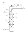
- FIG. 1 shows a schematic diagram of a preferred embodiment of a column according to the invention
- FIG. 2 shows a schematic diagram of a preferred embodiment for a first feed pipe, said pipe being substantially horizontally disposed in the column, in the region of the narrowest point of the cross-sectional narrowing in the first, substantially horizontal feed pipe and with a static mixing element downstream of the narrowest point of the cross-sectional narrowing in the first, substantially horizontal feed pipe and
- FIGS. 3A and 3B show examples of preferred embodiments of static mixing elements
- FIG. 1 shows a preferred embodiment for an inventive column K for performing an extractive distillation of a mixture of hydrocarbons and/or hydrocarbon derivatives 1 by running said mixture in countercurrent to a selective solvent 2 over separatory internals E, with a liquid distributor F disposed above said internals, the selective solvent 2 becoming laden in the column K with the components from the mixture to be separated 1 for which it has greater affinity and being withdrawn from the lower region of the column as laden selective solvent 3 while, by contrast, the components from the mixture to be separated for which the selective solvent 2 has a lower affinity remain in the vapor phase and are withdrawn as top stream 4 which is condensed to obtain a condensate 5 , some of which is withdrawn as product stream 6 , the remainder being reintroduced to the column K as reflux 7 .
- the selective solvent 2 is fed into the column via a substantially horizontal feed pipe R 1 above the internals E and the liquid distributor F.
- the substantially horizontal feed pipe R 1 has a geometry that induces a Venturi effect, i.e. the feed pipe R 1 has a cross-sectional narrowing to a narrowest point after which said pipe widens again, the reflux 7 being aspirated from a second feed pipe R 2 in the region of the narrowest point of the cross-sectional narrowing, without the need for a feed pump or static pressure.
- the schematic diagram in FIG. 2 elucidates the invention-essential admixing element for admixing the reflux 7 into the selective solvent 2 : the selective solvent 2 is supplied via a first feed pipe R 1 which exhibits a cross-sectional narrowing to a narrowest cross section V and subsequently widens again.
- the second feed pipe R 2 is arranged through which the reflux 7 is passed and admixed into the stream 2 of the selective solvent.
- the preferred embodiment shown achieves an additional improvement in mixing quality when a static mixer M is disposed downstream of the narrowest point V of the cross-sectional narrowing and transversely to the main flow direction through the first feed pipe R 1 .
- FIGS. 3A and 3B Preferred geometric configurations for static mixers M are shown in FIGS. 3A and 3B : in the shape of an annulus which is open at the top and is in contact with the lower interior wall of the pipe R 1 in FIG. 3A , and in the shape of an eccentrically disposed annulus likewise in contact with the lower interior wall of the first feed pipe R 1 but spaced apart from the upper interior wall of said pipe and secured thereto with supports in FIG. 3B .
- a stream of selective solvent 2 comprising an N-methylpyrolidone/water mixture having a density of 1013.7 kg/m 3 and a viscosity of 1.179 mPa ⁇ s.
- the reflux 7 introduced at a mass flow rate of 22 t/h comprises a mixture of butanes and butenes having a density of 572.1 kg/m 3 and a viscosity of 0.14 mPa ⁇ s.
- the extractive distillation column K has a commercially available perforated plate liquid distributor disposed in it above the separatory internals E.
- mixing quality X max /X av has a value of 6.8.
- X max presently describes the highest value in the measurement zone for the mass fraction of stream 7 .
- X av describes the average value in the measurement zone for the mass fraction of stream 7 , i.e. the value to be found in the entire measurement zone in the case of perfect mixing.
- Mixing quality is defined by the ratio X max /X av . Accordingly, mixing quality is 1 in the case of ideal mixing.
- the ratio X min /X av is defined analogously, i.e., as the ratio of the lowest value in the measurement zone to the average value in the measurement zone, in each case for the mass fraction of stream 7 .
- Admixing apparatus provided above the separatory internals E is a first, substantially horizontally disposed feed pipe R 1 exhibiting a cross-sectional narrowing to a narrowest point V, said pipe widening again afterwards.
- a second feed pipe R 2 joins therewith, partially protrudes into the first, substantially horizontal feed pipe R 1 and has a slanted end.
- a second feed pipe R 2 having an internal diameter of 50.8 mm protrudes into the first, substantially horizontal feed pipe R 1 to a protrusion depth of 49.2 mm at the upstream end and to a protrusion depth of 29.2 mm at the downstream end, i.e. the second feed pipe R 2 is slanted.
- the mixing quality values which follow are determined in a measurement zone defined as a cross section of the first, substantially horizontal feed pipe R 1 at a distance of 2 m downstream of the downstream-facing end of the narrowest point V of the cross-sectional narrowing: X max /X av equals 1.09 and X min /X av equals 0.85.
- the setup in Example 2 is the same as the setup in Example 1 except that, in addition, disposed downstream of the feed pipes R 1 and R 2 , there is a static mixing element M corresponding to the schematic diagram in FIG. 3B , which is in the shape of an eccentrically disposed ring and is made of a steel sheet and is of 4 mm in thickness, 260 mm in external diameter and 200 mm in internal diameter, said ring being in contact with the lower interior wall of the first, substantially horizontal feed pipe R 1 and being secured to the upper interior wall of said pipe with two supports.
- the mixing quality determined in this case is 1.02 for X max /X av and 0.99 for X min /X av .
Landscapes
- Chemical & Material Sciences (AREA)
- Chemical Kinetics & Catalysis (AREA)
- Organic Chemistry (AREA)
- Dispersion Chemistry (AREA)
- Oil, Petroleum & Natural Gas (AREA)
- Engineering & Computer Science (AREA)
- Analytical Chemistry (AREA)
- Water Supply & Treatment (AREA)
- General Chemical & Material Sciences (AREA)
- Vaporization, Distillation, Condensation, Sublimation, And Cold Traps (AREA)
- Organic Low-Molecular-Weight Compounds And Preparation Thereof (AREA)
- Production Of Liquid Hydrocarbon Mixture For Refining Petroleum (AREA)
Applications Claiming Priority (4)
| Application Number | Priority Date | Filing Date | Title |
|---|---|---|---|
| EP14176082.7 | 2014-07-08 | ||
| EP14176082 | 2014-07-08 | ||
| EP14176082 | 2014-07-08 | ||
| PCT/EP2015/065423 WO2016005359A1 (de) | 2014-07-08 | 2015-07-07 | Kolonne mit trennwirksamen einbauten zur auftrennung eines gemisches von kohlenwasserstoffen und/oder kohlenwasserstoffderivaten durch extraktivdestillation mit einem selektiven lösungsmittel |
Publications (2)
| Publication Number | Publication Date |
|---|---|
| US20170158583A1 US20170158583A1 (en) | 2017-06-08 |
| US10125063B2 true US10125063B2 (en) | 2018-11-13 |
Family
ID=51063355
Family Applications (1)
| Application Number | Title | Priority Date | Filing Date |
|---|---|---|---|
| US15/323,802 Active 2035-11-01 US10125063B2 (en) | 2014-07-08 | 2015-07-07 | Column with separative installations for separating a mixture of hydrocarbons and/or hydrocarbon derivatives by means of an extractive distillation using a selective solvent |
Country Status (8)
| Country | Link |
|---|---|
| US (1) | US10125063B2 (de) |
| EP (1) | EP3166705B1 (de) |
| JP (1) | JP6759183B2 (de) |
| KR (1) | KR102358867B1 (de) |
| CN (1) | CN106659945B (de) |
| BR (1) | BR112017000028B1 (de) |
| RU (1) | RU2694032C2 (de) |
| WO (1) | WO2016005359A1 (de) |
Families Citing this family (5)
| Publication number | Priority date | Publication date | Assignee | Title |
|---|---|---|---|---|
| KR102086048B1 (ko) | 2017-07-07 | 2020-03-06 | 주식회사 엘지화학 | 분산판 및 이를 포함하는 정제탑 |
| US11449577B2 (en) | 2019-11-20 | 2022-09-20 | Micron Technology, Inc. | Methods and apparatus for performing video processing matrix operations within a memory array |
| US11853385B2 (en) | 2019-12-05 | 2023-12-26 | Micron Technology, Inc. | Methods and apparatus for performing diversity matrix operations within a memory array |
| CN112451993B (zh) * | 2020-11-25 | 2022-02-01 | 中国石油化工股份有限公司 | 一种喷淋萃取设备和溶剂萃取方法 |
| CN116999883B (zh) * | 2023-08-07 | 2024-04-19 | 江苏诺恩作物科学股份有限公司 | 一种生产敌草快二氯盐的系统以及方法 |
Citations (9)
| Publication number | Priority date | Publication date | Assignee | Title |
|---|---|---|---|---|
| US2129684A (en) * | 1934-09-15 | 1938-09-13 | Eastman Kodak Co | Process and apparatus for removing water from aqueous aliphatic acids |
| US2610141A (en) | 1948-12-31 | 1952-09-09 | Standard Oil Dev Co | Extractive distillation process |
| FR2606291A1 (fr) | 1986-11-12 | 1988-05-13 | Elf Aquitaine | Fractionnement avec solvant supercritique |
| US4802630A (en) | 1985-11-19 | 1989-02-07 | Ecolab Inc. | Aspirating foamer |
| WO1999003554A1 (en) | 1997-07-18 | 1999-01-28 | Koch-Glitsch, Inc. | Venturi swirl tube for vapor liquid contact tray |
| US20050059838A1 (en) | 2002-09-03 | 2005-03-17 | Mitsubishi Chemical Corporation | Process for producing (meth)acrylic acid compound |
| CN101588851A (zh) | 2007-01-25 | 2009-11-25 | 巴斯夫欧洲公司 | 通过变压精馏从三烷/甲醛/水混合物中分离三烷的方法 |
| DE102010011014A1 (de) | 2010-03-11 | 2011-09-15 | Basf Se | Verfahren und Vorrichtung zur destillativen Gewinnung von Rein-1,3-Butadien aus Roh-1,3-Butadien |
| US9273829B2 (en) | 2012-10-09 | 2016-03-01 | Basf Se | Sorption store for storing gaseous substances |
Family Cites Families (5)
| Publication number | Priority date | Publication date | Assignee | Title |
|---|---|---|---|---|
| AU462261B2 (en) * | 1970-12-29 | 1975-06-19 | SNAMPROGETTI Sp. A | Process for the recovery of aromatic hydrocarbons from mixtures containing the same |
| DE2648638A1 (de) * | 1976-10-27 | 1978-05-03 | Metallgesellschaft Ag | Verfahren zur erhoehung der ausbeute an aromaten bei der extraktiven destillation |
| DE10219375A1 (de) * | 2002-04-30 | 2003-11-13 | Basf Ag | Kontinuierliches Verfahren zur Gewinnung von Butenen aus einem C4-Schnitt |
| DE10233620A1 (de) * | 2002-07-24 | 2004-02-12 | Basf Ag | Kontinuierliches Verfahren zur Auftrennung eines C4-Schnittes |
| DE10333756A1 (de) * | 2003-07-24 | 2005-02-17 | Basf Ag | Verfahren zur Auftrennung eines Roh-C4-Schnittes |
-
2015
- 2015-07-07 WO PCT/EP2015/065423 patent/WO2016005359A1/de not_active Ceased
- 2015-07-07 KR KR1020177003077A patent/KR102358867B1/ko active Active
- 2015-07-07 EP EP15734382.3A patent/EP3166705B1/de active Active
- 2015-07-07 JP JP2017501295A patent/JP6759183B2/ja active Active
- 2015-07-07 BR BR112017000028-8A patent/BR112017000028B1/pt active IP Right Grant
- 2015-07-07 RU RU2017103940A patent/RU2694032C2/ru active
- 2015-07-07 US US15/323,802 patent/US10125063B2/en active Active
- 2015-07-07 CN CN201580037020.9A patent/CN106659945B/zh active Active
Patent Citations (10)
| Publication number | Priority date | Publication date | Assignee | Title |
|---|---|---|---|---|
| US2129684A (en) * | 1934-09-15 | 1938-09-13 | Eastman Kodak Co | Process and apparatus for removing water from aqueous aliphatic acids |
| US2610141A (en) | 1948-12-31 | 1952-09-09 | Standard Oil Dev Co | Extractive distillation process |
| US2663679A (en) | 1948-12-31 | 1953-12-22 | Standard Oil Dev Co | Extractive distillation of alcohols obtained from olefins |
| US4802630A (en) | 1985-11-19 | 1989-02-07 | Ecolab Inc. | Aspirating foamer |
| FR2606291A1 (fr) | 1986-11-12 | 1988-05-13 | Elf Aquitaine | Fractionnement avec solvant supercritique |
| WO1999003554A1 (en) | 1997-07-18 | 1999-01-28 | Koch-Glitsch, Inc. | Venturi swirl tube for vapor liquid contact tray |
| US20050059838A1 (en) | 2002-09-03 | 2005-03-17 | Mitsubishi Chemical Corporation | Process for producing (meth)acrylic acid compound |
| CN101588851A (zh) | 2007-01-25 | 2009-11-25 | 巴斯夫欧洲公司 | 通过变压精馏从三烷/甲醛/水混合物中分离三烷的方法 |
| DE102010011014A1 (de) | 2010-03-11 | 2011-09-15 | Basf Se | Verfahren und Vorrichtung zur destillativen Gewinnung von Rein-1,3-Butadien aus Roh-1,3-Butadien |
| US9273829B2 (en) | 2012-10-09 | 2016-03-01 | Basf Se | Sorption store for storing gaseous substances |
Non-Patent Citations (7)
| Title |
|---|
| International Preliminary Report on Patentability and Written Opinion dated Jan. 19, 2017 in PCT/EP2015/065423 (submitting English translation only). |
| International Search Report dated Sep. 28, 2015 in PCT/EP2015/065423 filed Jul. 7, 2015. |
| U.S. Appl. No. 14/911,747, filed Feb. 12, 2016, US 2016-0186932 A1, Matthias Weickert et al. |
| U.S. Appl. No. 14/911,756, filed Feb. 12, 2016, US 2016-0201853 A1, Matthias Weickert et al. |
| U.S. Appl. No. 14/911,789, filed Feb. 12, 2016, US 2016-0201854 A1, Matthias Weickert et al. |
| U.S. Appl. No. 14/912,809, filed Feb. 18, 2016, US 2016-0207767 A1, Matthias Kern et al. |
| U.S. Appl. No. 14/915,035, filed Feb. 26, 2016, US 2016-0207852 A1, Matthias Kern et al. |
Also Published As
| Publication number | Publication date |
|---|---|
| BR112017000028B1 (pt) | 2021-11-09 |
| KR102358867B1 (ko) | 2022-02-08 |
| US20170158583A1 (en) | 2017-06-08 |
| WO2016005359A1 (de) | 2016-01-14 |
| BR112017000028A2 (pt) | 2017-10-31 |
| CN106659945B (zh) | 2019-07-05 |
| EP3166705B1 (de) | 2018-08-15 |
| RU2017103940A (ru) | 2018-08-08 |
| JP6759183B2 (ja) | 2020-09-23 |
| JP2017521248A (ja) | 2017-08-03 |
| CN106659945A (zh) | 2017-05-10 |
| RU2017103940A3 (de) | 2019-02-19 |
| EP3166705A1 (de) | 2017-05-17 |
| KR20170028964A (ko) | 2017-03-14 |
| RU2694032C2 (ru) | 2019-07-08 |
Similar Documents
| Publication | Publication Date | Title |
|---|---|---|
| US10125063B2 (en) | Column with separative installations for separating a mixture of hydrocarbons and/or hydrocarbon derivatives by means of an extractive distillation using a selective solvent | |
| EP2804689B1 (de) | Vorrichtung und verfahren zur trennung von kohlenwasserstoffen aus kohlenwasserstoffhaltigem wasser | |
| CN101171072B (zh) | 顺流分馏塔盘 | |
| US7128276B2 (en) | Method for mixing fluids | |
| PL206028B1 (pl) | Sposób otrzymywania surowego 1,3-butadienu z frakcji C₄ drogą destylacji ekstrakcyjnej i urządzenie do realizacji tego sposobu | |
| CN101927097B (zh) | 通过在具有一个或多个连续分隔壁的塔中蒸馏来分离一种或多种进料混合物的方法 | |
| KR20150010664A (ko) | 증류 장치 | |
| CA2501675A1 (en) | Method and device for extractive distillation | |
| CN100441553C (zh) | 获得粗1,3-丁二烯的方法 | |
| US20150299581A1 (en) | System and method of delivering dilution water droplets within an oil-and-water stream | |
| JP2013530827A (ja) | 分離カラムの供給セクション | |
| CN102448594A (zh) | 至并流蒸气-液体接触塔盘的改进流体分配 | |
| DK145733B (da) | Afgasningskolonne | |
| CN105327657A (zh) | 一种溢流型气液分配器 | |
| CA2911317A1 (en) | Systems and methods for recovering dimethyl ether from gas mixtures and liquid mixtures | |
| TW201739494A (zh) | 催化蒸餾塔中用於分配氣體及液體之新穎裝置 | |
| US20080128264A1 (en) | Three-phase extractive distillation with multiple columns connected in series | |
| RU2599400C1 (ru) | Многопоточная контактная тарелка | |
| TW202402371A (zh) | 具有交替隔室高度之萃取塔 | |
| RU2588527C2 (ru) | Секция подачи разделительной колонны | |
| RU2556006C1 (ru) | Способ ректификации углеводородных смесей | |
| RU2081662C1 (ru) | Способ ввода жидких смесей в разделительные аппараты | |
| KR20100132465A (ko) | 하나 이상의 백업 층 및 하나 이상의 분리 층을 갖는 구조화 패킹의 용도 | |
| RU2005128023A (ru) | Перекрестно-точный контактор-озонатор | |
| TH67446B (th) | อุปกรณ์สัมผัสและกระจายแบบหลายเฟสสำหรับกระบวนการไฮโดรโพรเซสซิง |
Legal Events
| Date | Code | Title | Description |
|---|---|---|---|
| AS | Assignment |
Owner name: BASF SE, GERMANY Free format text: ASSIGNMENT OF ASSIGNORS INTEREST;ASSIGNORS:HEIDA, BERND;HOFINGER, JULIA;RENZE, PETER;SIGNING DATES FROM 20150901 TO 20150922;REEL/FRAME:040839/0410 |
|
| STCF | Information on status: patent grant |
Free format text: PATENTED CASE |
|
| MAFP | Maintenance fee payment |
Free format text: PAYMENT OF MAINTENANCE FEE, 4TH YEAR, LARGE ENTITY (ORIGINAL EVENT CODE: M1551); ENTITY STATUS OF PATENT OWNER: LARGE ENTITY Year of fee payment: 4 |