US10274506B2 - Automatic analytical apparatus - Google Patents
Automatic analytical apparatus Download PDFInfo
- Publication number
- US10274506B2 US10274506B2 US15/111,623 US201515111623A US10274506B2 US 10274506 B2 US10274506 B2 US 10274506B2 US 201515111623 A US201515111623 A US 201515111623A US 10274506 B2 US10274506 B2 US 10274506B2
- Authority
- US
- United States
- Prior art keywords
- container
- sample
- liquid
- actuator
- liquid surface
- Prior art date
- Legal status (The legal status is an assumption and is not a legal conclusion. Google has not performed a legal analysis and makes no representation as to the accuracy of the status listed.)
- Active
Links
Images



Classifications
-
- G—PHYSICS
- G01—MEASURING; TESTING
- G01N—INVESTIGATING OR ANALYSING MATERIALS BY DETERMINING THEIR CHEMICAL OR PHYSICAL PROPERTIES
- G01N35/00—Automatic analysis not limited to methods or materials provided for in any single one of groups G01N1/00 - G01N33/00; Handling materials therefor
- G01N35/02—Automatic analysis not limited to methods or materials provided for in any single one of groups G01N1/00 - G01N33/00; Handling materials therefor using a plurality of sample containers moved by a conveyor system past one or more treatment or analysis stations
- G01N35/04—Details of the conveyor system
-
- G—PHYSICS
- G01—MEASURING; TESTING
- G01F—MEASURING VOLUME, VOLUME FLOW, MASS FLOW OR LIQUID LEVEL; METERING BY VOLUME
- G01F23/00—Indicating or measuring liquid level or level of fluent solid material, e.g. indicating in terms of volume or indicating by means of an alarm
- G01F23/22—Indicating or measuring liquid level or level of fluent solid material, e.g. indicating in terms of volume or indicating by means of an alarm by measuring physical variables, other than linear dimensions, pressure or weight, dependent on the level to be measured, e.g. by difference of heat transfer of steam or water
- G01F23/28—Indicating or measuring liquid level or level of fluent solid material, e.g. indicating in terms of volume or indicating by means of an alarm by measuring physical variables, other than linear dimensions, pressure or weight, dependent on the level to be measured, e.g. by difference of heat transfer of steam or water by measuring the variations of parameters of electromagnetic or acoustic waves applied directly to the liquid or fluent solid material
- G01F23/284—Electromagnetic waves
- G01F23/292—Light, e.g. infrared or ultraviolet
- G01F23/2921—Light, e.g. infrared or ultraviolet for discrete levels
- G01F23/2928—Light, e.g. infrared or ultraviolet for discrete levels using light reflected on the material surface
-
- G—PHYSICS
- G01—MEASURING; TESTING
- G01N—INVESTIGATING OR ANALYSING MATERIALS BY DETERMINING THEIR CHEMICAL OR PHYSICAL PROPERTIES
- G01N35/00—Automatic analysis not limited to methods or materials provided for in any single one of groups G01N1/00 - G01N33/00; Handling materials therefor
- G01N35/00584—Control arrangements for automatic analysers
- G01N35/00722—Communications; Identification
- G01N35/00732—Identification of carriers, materials or components in automatic analysers
-
- G—PHYSICS
- G01—MEASURING; TESTING
- G01N—INVESTIGATING OR ANALYSING MATERIALS BY DETERMINING THEIR CHEMICAL OR PHYSICAL PROPERTIES
- G01N35/00—Automatic analysis not limited to methods or materials provided for in any single one of groups G01N1/00 - G01N33/00; Handling materials therefor
- G01N35/0099—Automatic analysis not limited to methods or materials provided for in any single one of groups G01N1/00 - G01N33/00; Handling materials therefor comprising robots or similar manipulators
-
- G—PHYSICS
- G01—MEASURING; TESTING
- G01N—INVESTIGATING OR ANALYSING MATERIALS BY DETERMINING THEIR CHEMICAL OR PHYSICAL PROPERTIES
- G01N35/00—Automatic analysis not limited to methods or materials provided for in any single one of groups G01N1/00 - G01N33/00; Handling materials therefor
- G01N35/02—Automatic analysis not limited to methods or materials provided for in any single one of groups G01N1/00 - G01N33/00; Handling materials therefor using a plurality of sample containers moved by a conveyor system past one or more treatment or analysis stations
- G01N35/025—Automatic analysis not limited to methods or materials provided for in any single one of groups G01N1/00 - G01N33/00; Handling materials therefor using a plurality of sample containers moved by a conveyor system past one or more treatment or analysis stations having a carousel or turntable for reaction cells or cuvettes
-
- B—PERFORMING OPERATIONS; TRANSPORTING
- B01—PHYSICAL OR CHEMICAL PROCESSES OR APPARATUS IN GENERAL
- B01L—CHEMICAL OR PHYSICAL LABORATORY APPARATUS FOR GENERAL USE
- B01L9/00—Supporting devices; Holding devices
- B01L9/50—Clamping means, e.g. tongs
-
- G01F23/0069—
-
- G—PHYSICS
- G01—MEASURING; TESTING
- G01F—MEASURING VOLUME, VOLUME FLOW, MASS FLOW OR LIQUID LEVEL; METERING BY VOLUME
- G01F23/00—Indicating or measuring liquid level or level of fluent solid material, e.g. indicating in terms of volume or indicating by means of an alarm
- G01F23/80—Arrangements for signal processing
- G01F23/802—Particular electronic circuits for digital processing equipment
-
- G—PHYSICS
- G01—MEASURING; TESTING
- G01N—INVESTIGATING OR ANALYSING MATERIALS BY DETERMINING THEIR CHEMICAL OR PHYSICAL PROPERTIES
- G01N35/00—Automatic analysis not limited to methods or materials provided for in any single one of groups G01N1/00 - G01N33/00; Handling materials therefor
- G01N35/02—Automatic analysis not limited to methods or materials provided for in any single one of groups G01N1/00 - G01N33/00; Handling materials therefor using a plurality of sample containers moved by a conveyor system past one or more treatment or analysis stations
- G01N35/04—Details of the conveyor system
- G01N2035/0401—Sample carriers, cuvettes or reaction vessels
- G01N2035/0403—Sample carriers with closing or sealing means
- G01N2035/0405—Sample carriers with closing or sealing means manipulating closing or opening means, e.g. stoppers, screw caps, lids or covers
-
- G—PHYSICS
- G01—MEASURING; TESTING
- G01N—INVESTIGATING OR ANALYSING MATERIALS BY DETERMINING THEIR CHEMICAL OR PHYSICAL PROPERTIES
- G01N35/00—Automatic analysis not limited to methods or materials provided for in any single one of groups G01N1/00 - G01N33/00; Handling materials therefor
- G01N35/02—Automatic analysis not limited to methods or materials provided for in any single one of groups G01N1/00 - G01N33/00; Handling materials therefor using a plurality of sample containers moved by a conveyor system past one or more treatment or analysis stations
- G01N35/04—Details of the conveyor system
- G01N2035/0401—Sample carriers, cuvettes or reaction vessels
- G01N2035/0412—Block or rack elements with a single row of samples
-
- G—PHYSICS
- G01—MEASURING; TESTING
- G01N—INVESTIGATING OR ANALYSING MATERIALS BY DETERMINING THEIR CHEMICAL OR PHYSICAL PROPERTIES
- G01N35/00—Automatic analysis not limited to methods or materials provided for in any single one of groups G01N1/00 - G01N33/00; Handling materials therefor
- G01N35/02—Automatic analysis not limited to methods or materials provided for in any single one of groups G01N1/00 - G01N33/00; Handling materials therefor using a plurality of sample containers moved by a conveyor system past one or more treatment or analysis stations
- G01N35/04—Details of the conveyor system
- G01N2035/0474—Details of actuating means for conveyors or pipettes
- G01N2035/0491—Position sensing, encoding; closed-loop control
- G01N2035/0493—Locating samples; identifying different tube sizes
-
- G—PHYSICS
- G01—MEASURING; TESTING
- G01N—INVESTIGATING OR ANALYSING MATERIALS BY DETERMINING THEIR CHEMICAL OR PHYSICAL PROPERTIES
- G01N35/00—Automatic analysis not limited to methods or materials provided for in any single one of groups G01N1/00 - G01N33/00; Handling materials therefor
- G01N35/02—Automatic analysis not limited to methods or materials provided for in any single one of groups G01N1/00 - G01N33/00; Handling materials therefor using a plurality of sample containers moved by a conveyor system past one or more treatment or analysis stations
- G01N35/04—Details of the conveyor system
- G01N2035/0474—Details of actuating means for conveyors or pipettes
- G01N2035/0491—Position sensing, encoding; closed-loop control
- G01N2035/0494—Detecting or compensating piositioning errors
-
- G—PHYSICS
- G01—MEASURING; TESTING
- G01N—INVESTIGATING OR ANALYSING MATERIALS BY DETERMINING THEIR CHEMICAL OR PHYSICAL PROPERTIES
- G01N35/00—Automatic analysis not limited to methods or materials provided for in any single one of groups G01N1/00 - G01N33/00; Handling materials therefor
- G01N35/0098—Automatic analysis not limited to methods or materials provided for in any single one of groups G01N1/00 - G01N33/00; Handling materials therefor involving analyte bound to insoluble magnetic carrier, e.g. using magnetic separation
Definitions
- the present invention relates to an automatic analytical apparatus including an imaging device which images liquid in a container containing the liquid or a pipetting device which pipets the liquid.
- Examples of a method for grasping a liquid surface height include a method for obtaining an image and information on a container containing liquid and liquid in the container by such as a camera or a laser source from the outside of the container and a method for detecting a position of a liquid surface height based on a change in a capacitance when a probe tip and a liquid surface come into contact when the suction probe is moved down in the container.
- PTL 1 discloses that a sample checker which irradiates a side wall of a container with a laser source to check a specimen in a blood collection tube includes a chuck mechanism for clamping and fixing the blood collection tube during irradiation of the laser source.
- a specimen transport apparatus and an automatic analytical apparatus need to accurately grasp a liquid surface height.
- a blood collection tube with a small diameter is less firmly held than a blood collection tube with a large diameter. Therefore, it is assumed that the blood collection tube might be carried in an inclined state or the tube might not be centered since the center of the blood collection tube is varied. For example, if a container is inclined or is not centered when information on a liquid surface height is obtained by a camera and a laser, the liquid surface height information may not be accurately obtained. Further, further, in a pipetting process, since a container is not centered, a liquid surface position is varied, and reproductivity of trace pipetting may not be secured.
- an object of the present invention is to provide a container holding device capable of suppressing a backtracking operation by a user, a delay of the result report, and a decrease in reliability of the analysis result by performing a process after a, container is certainly centered.
- a container-clamping apparatus for clamping a container transported by a transport mechanism.
- the container-clamping apparatus includes at least two container holding members, an arm, and a connection member.
- the container holding members hold a side wall of the container.
- the arm moves the container holding members toward the container.
- the connection member connects the arm and the container holding member. At least apart of the container holding member or the connection member is formed of an elastic body.
- a container is centered which is held by a chuck mechanism. Consequently an accurate liquid surface position can be detected, and highly reproductive liquid pipetting can be realized.
- FIG. 1A is a view illustrating a state in which a holder using an arm opening/closing mechanism is opened by a linear movement in an embodiment of the present invention.
- FIG. 1B is a view illustrating a state in which the holder using the arm opening/closing mechanism is closed by a linear movement in the embodiment of the present invention.
- FIG. 1C is an overall view of the holder using the arm opening/closing mechanism by a linear movement in the embodiment of the present invention.
- FIG. 2A is a view illustrating a state in which a holder using an arm opening/closing mechanism is opened by a rotational movement in an embodiment of the present invention.
- FIG. 2B is a view illustrating a state in which the holder using the arm opening/closing mechanism is closed by a rotational movement in the embodiment of the present invention.
- FIG. 2C is an overall view of the holder using the arm opening/closing mechanism by a rotational movement in the embodiment of the present invention.
- FIG. 3 is a configuration view of a sample checker including a container holding mechanism according to an embodiment of the present invention.
- FIG. 4 is a configuration view of an automatic analytical apparatus using a vibration suppression mechanism between a holder and a holder attachment unit in another embodiment of the present invention.
- FIG. 5 is an overall view of the automatic analytical apparatus including the container holding mechanism according to the present invention.
- FIG. 6A is a view illustrating a state in which a holder using an arm opening/closing mechanism is opened by a linear movement in which the center of a container can be predominantly positioned in an embodiment of the present invention.
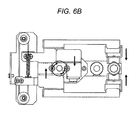
- FIG. 6B is a view illustrating a state in which the holder using the arm opening/closing mechanism is closed by a linear movement in which the center of a container can be predominantly positioned in the embodiment of the present invention.
- FIG. 6C is an overall view of the holder using the arm opening/closing mechanism by a linear movement in which the center of a container can be predominantly positioned in the embodiment of the present invention.
- FIGS. 1A and 1B are views illustrating the container holder 100 from an upper surface side.
- FIG. 1A illustrates a state in which the container holder 100 is not holding a container.
- FIG. 1B illustrates a state in which the container holder 100 is holding the container.
- FIG. 1C illustrates an overall view of the container holder 100 and a container 101 erected on a rack 102 as an example of a holding target.
- a container-clamping apparatus 100 includes an actuator 103 , an opening/closing arm 104 , an elastic body 105 , a container holding member 106 , and a linear movement mechanism 107 .
- Power generated by rotation of the actuator 103 is transmitted to the opening/closing arm 104 via a link mechanism 108 , and the opening/closing arm 104 opens and closes on right and left sides.
- the opening/closing arm 104 linearly drives by the linear movement mechanism 107 so as to open on right and left sides in association with driving of the actuator 103 .
- the elastic body 105 is provided to each of the opening/closing arms 104 for suppressing vibration and centering a container. Further, the container holding member 106 is provided to a tip of the elastic body 105 . Since the container holding member 106 is connected via the elastic body 105 , the elastic body is compressed when holding a container ( FIG. 1B ). Therefore, the container is pushed by the same elastic body from the both sides, and the center of containers having various diameters can be also positioned at a same position. Further, even if a container is inclined, the container can be held upright by applying the same elastic force from both sides of the container.
- the vibration is absorbed by the elastic body 105 . Therefore, the vibration is not transmitted to a container held by the container-clamping apparatus 105 , and the container can be stably held.
- a vibration suppression mechanism is configured as a spring connected to each arm opening/closing mechanism.
- the vibration suppression mechanism may be an elastic body, such as rubber, other than a spring.
- the container holding member 106 is formed in a block body having a recess such that the member can hold a container having a cylindrical shape.
- the member may have another shape depending on a container shape.
- a basic operation of the container-clamping apparatus 100 according to the example will be described next.
- an operation for holding a test tube mounted on a rack will be described as an example of a holding target container.
- the present invention is not limited to this embodiment.
- a detector (not illustrated) is provided near the container-clamping apparatus 100 .
- the detector detects that a container to be held arrives through a lower side of the container-clamping apparatus 100 .
- a known detecting means such as a light sensor, an RFID reader, a bar code reader may be used.
- detection method arrival of a specimen container may be detected, and after arrival of the rack 102 is detected, a test tube mounted on the rack 102 may be transported so as to move to an appropriate holding position of the container-clamping apparatus 100 .
- the opening/closing arm 104 shifts to a closed position by which the actuator 103 rotationally drives, and the link mechanism 108 pushing the opening/closing arm 104 on both sides to open moves to a position where the link mechanism 108 does not come into contact with the opening/closing arm.
- the actuator 103 is driven by a motor 109 .
- the motor 109 rotationally drives the actuator 103 .
- an amount to move in a direction in which the opening/closing arms 104 approach each other is preferably larger than a movement amount needed to cause the container holding member 106 to come into contact with a side surface of a container. Accordingly, in the case of holding the container (as illustrated in FIG. 1B ), the elastic body 105 is compressed at all times, and a repulsive force is generated between a side surface of the container and the opening/closing arm.
- a pair of the opening/closing arms includes the elastic body 105 having an elastic modulus which is the same on right and left sides. Therefore, a container held by the container holding member 106 is pushed by the same force from both sides.
- the pair of the opening/closing arms is driven by rotation of an actuator, a driving amount thereof is constant at all times. Therefore, even if a position of the container is deviated, the center of the container can be held and centered at all times at the same position since the container is pushed by the same force from the both sides. Further, the same repulsive force is applied from both sides of the container. Therefore, even if the containers have various diameters, the center of the container can be held at the same position.
- the same repulsive force is applied to a side surface of a container held by the container holding member 106 from both sides. Therefore, even if a shaft center of a container is inclined, the container can be held at a correct position, and as illustrated in FIG. 1B , the container can be held at all times at the same position and in the same state.
- the sample container 101 is assumed which has a test tube shape and is erected on the rack 102 which can carry a plurality of test containers.
- the container is not limited thereto.
- a test container carried by a holder which can mount one test tube may be held, and a reagent bottle containing a reagent and a reaction vessel for storing reaction liquid in which a sample and a reagent are mixed may be held.
- An external shape of these containers may be other than a cylindrical shape.
- a container holding member preferably has an appropriate shape along an external shape of a container to be held.
- FIG. 2A illustrates a state in which the container-clamping apparatus 200 does not hold a container (an upper surface view).
- FIG. 2B illustrates a state in which the container-clamping apparatus 200 holds the container (an upper surface view).
- FIG. 2C illustrates a state in which the container-clamping apparatus 200 holds a container 101 (a perspective view).
- the container holding device 200 includes an actuator 201 , an opening/closing arm 202 , an elastic body 203 , a container holding member 204 , a spring 205 , and a motor 207 .
- Power generated by rotation of the actuator 201 is transmitted to the opening/closing arm 202 through link mechanisms 206 and 206 ′, and the opening/closing arm 202 is opened and closed on right and left sides.
- a container holding member is fixed at the rear of the mechanism in the opening/closing arm 202 . Therefore, the container holding member rotationally drives so as to hold or release a container in association with driving of the actuator 201 .
- the container holding member 204 includes a roller mechanism.
- the roller mechanism includes a shaft extending in a length direction of a container and two rollers provided at both ends of the shaft, and two roller mechanisms are provided to each opening/closing arm.
- a controller rotates the actuator 201 to shift the opening/closing arm 202 in an open state to a close state, and holds a container.
- effects similar to that in the example 1 can be realized by a different configuration, and even if a container position is deviated from a holding position, the center of the container can be held at all times and centered at the same position since the container is pushed by the same force from the both sides. Since a pressure is applied by an elastic body from both sides of the container, even if a diameter of the container is varied, the center of the container can be held at the same position.
- the vibration is absorbed by the elastic body 203 , and the vibration is not transmitted to the held container.
- a bar code reader 313 illustrated in FIG. 3 reads a bar code 312 attached on a side surface of a container 101 .
- Information for specifying a container type can be obtained from the bar code 112 , and by inquiring the read information to a database stored in a device controller 311 , information on the difference of the shape of the container 101 can be preliminary obtained from registered container information.
- Container shape information may be directly read from the bar code 312 .
- a rotation frequency of an actuator provided to a container holder can be changed. For example, in the case where the container diameter is ⁇ 13 mm, the rotation frequency of the actuator is increased in comparison with a container having a diameter of ⁇ 16 mm. Consequently, an elastic body can be sufficiently compressed even while holding a small diameter container, and a holding force can be adjusted to the optimum force. Further, when a large diameter container is held, an excessive force is not applied, and the container is hardly damaged. Furthermore, a container can be held according to a shape such that effects by external vibration such as device vibration is suppressed. An arbitrary configuration written in other examples can be used in a specific configuration of the container holding device 300 .
- the sample checker includes a function to detect foam on a liquid surface of a sample in a blood collection tube by an imaging means such as a camera before pipetting and analyzing the sample.
- a sample to be checked is erected on a rack 102 in a state in which the sample is put in a container 101 such as a blood collection tube and transported in an automatic analytical apparatus by using a transport means such as a belt conveyor.
- An apparatus which can transport, on a belt conveyor, a rack which can mount multiple containers will be exemplified in the example.
- the present invention is not limited to this embodiment.
- a sample disk which rotationally drives by arranging sample containers on the circumference and the sample checker may be combined. Further, the apparatus may separately carry a holder mounting one container on a belt conveyor.
- a container type which can be used might be specified in some apparatus. However, according to user usage, multiple container types may be mixedly used. For example, a small container is used for a trace sample, and a container having a large internal volume such as a blood collection tube is used for a large volume sample. A small container may be erected at an opening of the blood collection tube.
- a bar code 312 can be attached to a container 101 for identification, and such as a sample type can be recognized by reading the bar code 312 by a bar code reader 313 .
- a bar code reader 313 Other than the bar code, a two-dimensional code, an RFID tag, and an IC chip may be attached.
- a sample checker includes a reader corresponding to each storage medium.
- a sample contained in the container 101 might have a foam 303 on a liquid surface.
- the foam 303 is generally visually confirmed before a user processes a sample, and the foam is appropriately removed by such as foam breaking.
- foam breaking it is difficult to totally remove the foam 303 .
- a pipetting probe which has a probe mounting a function to detect a position of a liquid surface by measuring, in real time, a change in a physical quantity of such as a resistance, a capacitance, an inner pressure in a probe, and a probe vibration frequency, which are a physical quantity changed when coming into contact with a liquid surface to reduce an immersed amount of the pipetting probe.
- a liquid surface detection is used to minimize an immersed contamination amount of a pipetting probe 304 and is an essential function in an automatic analytical apparatus since there are various types of sample containers 101 , and an amount of filled sample is not fixed.
- a conventional liquid surface detection function cannot distinct the foam 303 as a liquid surface. In this case, a film and a foam are incorrectly determined as a liquid surface, and suction is performed without coming into contact with an analysis target. Therefore, an originally needed amount is not separated, and an accurate analysis result may not be output.
- foam is detected by an imaging unit 306 at a sample separating position (a position for temporary stop) for separating a sample.
- a lighting 307 is irradiated from upward at a position for temporary stop for separating a sample.
- the imaging unit 306 is provided on an upper side of a blood collection tube as well as the lighting 307 and images a reflected light which is a light returned when a lighting light 308 from the lighting 307 reflects on a target sample liquid surface.
- the lighting 307 may be a white light source, and the imaging unit may be a camera which images an image of a liquid surface.
- the lighting may be a laser light
- the imaging unit may be a light receiving element obtaining a reflected light from a liquid surface.
- An image analysis unit 310 detects foam on a sample liquid surface in a container by image-processing an obtained image.
- a position where the imaging unit is provided is not limited to an upper side of a blood collection tube, and the imaging unit may be provided on a side, a lower side, or an oblique upper side of the blood collection tube.
- the device controller 311 determines that sample separating by the pipetting probe 304 is “negative”. Consequently, the device controller 311 carries the container on an abnormal sample tray. In the case where foam is not detected and in the case where foam is detected at a position where does not affect the separating operation, sample separating by the pipetting probe 304 is determined as “possible”, and the device controller 311 carries the container on a normal sample tray or carries the container to a separation device through a transport line.
- the imaging unit 306 is generally image-photographing by a camera. However, the unit can be replaced to a variation measurement of a target by a laser.
- the container 101 to be used various containers are used depending on a purpose as described above.
- a centroid position of the container 101 mounted on the rack 102 is low, the container is stable in a state mounted on the rack and hardly affected by external vibration such as device vibration.
- the container is easily affected by external vibration such as device vibration. If a container is vibrated by external vibration during imaging, an image obtained for sample check is likely to be blurred, and foam might be erroneously detected.
- the container 101 is held by the container-clamping apparatus 300 when the container 101 is imaged to suppress blurring by external vibration such as device vibration on the image obtained for sample check.
- the container may be controlled so as to be held at all times without having a process to detect a container type.
- the center of a container is positioned at the same position regardless of a container type. Therefore, existence and a position of a foam can be accurately detected when foam is detected. Further, in a state in which device vibration may occur during sample check, the sample checker can suppress a deviation of a liquid surface position by the vibration and accurately detect a state of foam on a liquid surface.
- a pipetting device including a container holding device 400 will be described with reference to FIG. 4 .
- a description will be omitted regarding a content which is not changed from other examples.
- the pipetting device in the example moves a probe 402 downward in a container and suctions a predetermined amount of samples from the vicinity of a sample liquid surface when a sample container mounted on a carried rack is carried at a pipetting position.
- the probe 402 which has been suctioned the sample moves upward and comes out of the container. Then, the probe 402 discharges the suctioned sample by a rotation movement or a horizontal movement in a reaction vessel (not illustrated) disposed at other position. Consequently, the predetermined amount of samples can be separated in another container.
- a sample is generally separated at a position where the pipetting probe moves downward by a predetermined amount after detecting a liquid surface position.
- a liquid surface moves by vibration, and detecting an accurate liquid surface position may be difficult.
- the pipetting probe accurately detects a liquid surface position, a side area of a probe coming into contact with a sample is increased when the liquid surface moves by vibration after detection, and contamination by suctioning a next sample liquid in a state in which a sample is attached on a side surface of the probe may increasingly occur.
- the container holding device 400 includes an elastic body 401 between with a container-clamping apparatus attachment unit 403 for attaching the container holding device to a case of a pipetting device. Therefore, even if an elastic body is not provided between an opening/closing arm of the container holder 400 and a container holding mechanism, effects by external vibration is absorbed by the elastic body 401 , and therefore a configuration of the container holding device 400 can be simplified.
- an elastic body 201 is provided between the container holding device 400 and the container holder attachment unit 403 , and therefore, in comparison with the case where the elastic body is provided at a tip of the container-clamping apparatus 400 , the elastic body can be disposed on a wide area, and vibration can be effectively suppressed.
- the container-clamping apparatus 400 stably clamps a container at a pipetting position, even in the case where external vibration occurs when a sample is separated, it can be prevented that the vibration is transmitted to liquid in a container. Consequently, a liquid surface does not vibrate when a pipetting probe moves downward, and pipetting accuracy is stabilized.
- the container holding device according to the example may be replaced to a configuration described in other examples according to the present invention.
- an automatic analytical apparatus including a container-clamping apparatus 105
- the automatic analytical apparatus include, but not limited to, various type apparatuses, such as a biochemical analytical apparatus, an immune analytical apparatus, a coagulation analytical apparatus.
- a biochemical analytical apparatus such as a biochemical analytical apparatus, an immune analytical apparatus, a coagulation analytical apparatus.
- the automatic immune analytical apparatus includes such as a sample rack 10 , a reagent disk 11 , a container lid opening/closing mechanism 12 , a sample pipetting mechanism 13 , a reagent pipetting mechanism 14 , a magnetic particle agitation mechanism 15 , a magazine 16 , a reaction tank 17 , a transport mechanism 20 , a chip discarding unit 21 , a transport mechanism 23 , an impurity suction mechanism 24 , a washing liquid discharging mechanism 25 , a transport mechanism 27 , and a reagent discharging mechanism 28 .
- a sample is placed on the sample rack 10 .
- the reagent disk 11 stores a reagent container 11 a having a lid, which contains a reagent and magnetic particles needed in an immune reaction.
- the container lid opening/closing mechanism 12 opens and closes a lid of the reagent container 11 a having the lid.
- the sample pipetting mechanism 13 pipets and separates a sample.
- the reagent pipetting mechanism 14 pipets and separates a reagent and magnetic particles from the reagent container 11 a having a lid.
- the magnetic particle agitation mechanism 15 agitates magnetic particles in the reagent container 11 a having a lid.
- the magazine 16 stores a reaction vessel 16 a (hereinafter called a vessel) to be used in reaction and a chip 16 b to be used for pipetting and separating a sample.
- the reaction tank 17 can control a temperature to react a sample and a reagent in the vessel 16 a .
- the transport mechanism 20 transports the vessel 16 a to the reaction tank 17 and a vessel discarding unit 18 and transports the chip 16 b to a buffer 19 which temporarily stores a sample for pipetting.
- the chip discarding unit 21 discards the chip 16 b used for pipetting of the sample.
- the transport mechanism 23 transports the vessel 16 a from the reaction tank 17 to a magnetic separator 22 or from the magnetic separator 22 to the reaction tank 17 .
- the impurity suction mechanism 24 suctions liquid including impurities in the vessel 16 a transported by the magnetic separator 22 .
- the washing liquid discharging mechanism 25 discharges washing liquid in the vessel 16 a transported to the magnetic separator 22 .
- the transport mechanism 27 transports the vessel 16 a from the reaction tank 17 to a detection unit 26 or from the detection unit 26 to the reaction tank 17 .
- the reagent discharging mechanism 28 discharges a reagent for detection to the vessel 16 a transported to the detection unit 26 .
- the transport mechanism 20 the vessel 16 a is transported on the reaction tank 17 from the magazine 16 , and also the chip 16 b is transported to the buffer 19 .
- the reaction tank 17 rotates, and the transported vessel 16 a moves to a reagent pipetting position.
- a reagent is pipetted from the reagent disk 11 to the vessel 16 a on the reaction tank 17 .
- the reaction tank 17 rotates again, and the vessel 16 a moves to the sample pipetting position.
- the chip 16 b transported to the buffer 19 is mounted to a chip holder by an upward and downward operation of the sample pipetting mechanism 13 , and a sample is separated from the sample rack 10 and pipetted to the vessel 16 a moved to the sample pipetting position.
- the used chip 16 b is discharged to the chip discarding unit 21 by an upward and downward operation of the sample pipetting mechanism 13 .
- the vessel 16 a in which a sample and a reagent have been pipetted moves to a reagent pipetting position by reaction of the reaction tank 17 after waiting for a reaction for a certain period of time in the reaction tank 17 , and magnetic particles are pipetted and separated from the reagent disk 11 by the reagent pipetting mechanism 14 . Further, after waiting for a reaction for a certain period of time in the reaction tank 17 , the reaction tank 17 rotates, and the vessel 16 a on the reaction tank 17 is transported to the magnetic separator 22 by the transport mechanism 23 .
- the magnetic separator 22 repeats suctioning by the impurity suction mechanism 24 and discharging washing liquid by the washing liquid discharging mechanism 25 several times. Consequently, magnetic components including reaction products are remained in the vessel 16 a , and the vessel 16 a is returned to the reaction tank 17 by the transport mechanism 23
- the reaction tank 17 rotates, and the vessel 16 a is transported to the detection unit 26 by the transport mechanism 27 , a reagent for detection is discharged by the reagent discharging mechanism 28 to the vessel 16 a , and detection is performed.
- the vessel 16 a which has been detected is returned to the reaction tank 17 by the transport mechanism 27 , the reaction tank 17 rotates, and the vessel 16 a is discarded to the vessel discarding unit 18 by the transport mechanism 20 . After that, the above-described operation is repeated to a sample to be used.
- the container-clamping apparatus 105 is provided on an upper side of a position where the sample pipetting mechanism 13 separates a sample from the sample rack 10 .
- the container-clamping apparatus By providing the container-clamping apparatus at this position, while separating a liquid surface of the transported sample, vibration caused by operations by other mechanisms in an automatic immune analytical apparatus is not transmitted to a sample, and the sample can be accurately separated.
- the immune analytical apparatus may include a sample check mechanism.
- Existence of foam on a liquid surface can be checked by irradiating a lighting light and a laser light to a sample liquid surface for sample check and by checking a reflected light from a liquid surface by an imaging unit such as a camera and a light detector.
- an imaging unit such as a camera and a light detector.
- the sample check mechanism is preferably provided at a position which is same as a pipetting position by the sample pipetting mechanism or an upper stream side than the position. In the case where a pipetting position and a sample check position are the same, a container holder according to the present invention can be commonly used, and a number of mechanisms can be decreased.
- the container-clamping apparatus 105 may hold a reagent container at a position where the reagent pipetting mechanism 14 pipets a reagent contained in a reagent container and a position where the magnetic particle agitation mechanism 15 agitates a reagent.
- effects on a reagent by vibration caused by operations of peripheral mechanisms can be suppressed, and the reagent can be separated and agitated always in the same state.
- the container holder may hold the vessel 16 a at a suction position by the impurity suction mechanism 24 which separates impurities other than magnetic particles in the vessel 16 a containing reaction liquid. In this case, impurities can be removed in the vessel always in the same state.
- FIGS. 6A to 6C A description overlapping with that in the Example 1 will be omitted.
- FIGS. 6A and 6B are views illustrating a container holder from an upper surface side.
- FIG. 6A illustrates a state in which the container holder is not holding a container.
- FIG. 6B illustrates a state in which the container holder is holding the container.
- FIG. 6C illustrates an overall view of the container holder and a container 101 erected on a rack 102 as an example of a holding target.
- a basic configuration and an operation outline of the container-clamping apparatus 600 are similar to those in the Example 1. However, a spring 601 , a belt 602 , and a pulley 603 which support a liner movement are added in comparison with the Example 1. Further, a container holding member 605 and a connection member 606 for connecting the container holding member 605 to an opening/closing arm 604 are provided to a tip of the opening/closing arm 604 .
- the connection member 606 is formed of a rigid material.
- At least a part of the container holding member 605 is formed of an elastic body such as rubber, and therefore, a centering function of a container described in the Examples 1 and 2 can be achieved by which the elastic body portion is compressed when the container is held.
- a whole of the container holding member 605 may be formed of an elastic body, or a part of the member may be formed of the elastic body, and other parts may be formed of a rigid member.
Landscapes
- Physics & Mathematics (AREA)
- Chemical & Material Sciences (AREA)
- General Physics & Mathematics (AREA)
- Immunology (AREA)
- Analytical Chemistry (AREA)
- Biochemistry (AREA)
- General Health & Medical Sciences (AREA)
- Life Sciences & Earth Sciences (AREA)
- Health & Medical Sciences (AREA)
- Pathology (AREA)
- Electromagnetism (AREA)
- Robotics (AREA)
- Chemical Kinetics & Catalysis (AREA)
- Engineering & Computer Science (AREA)
- Thermal Sciences (AREA)
- Fluid Mechanics (AREA)
- Automatic Analysis And Handling Materials Therefor (AREA)
Applications Claiming Priority (3)
| Application Number | Priority Date | Filing Date | Title |
|---|---|---|---|
| JP2014-012084 | 2014-01-27 | ||
| JP2014012084 | 2014-01-27 | ||
| PCT/JP2015/051158 WO2015111526A1 (ja) | 2014-01-27 | 2015-01-19 | 自動分析装置 |
Publications (2)
| Publication Number | Publication Date |
|---|---|
| US20160334431A1 US20160334431A1 (en) | 2016-11-17 |
| US10274506B2 true US10274506B2 (en) | 2019-04-30 |
Family
ID=53681330
Family Applications (1)
| Application Number | Title | Priority Date | Filing Date |
|---|---|---|---|
| US15/111,623 Active US10274506B2 (en) | 2014-01-27 | 2015-01-19 | Automatic analytical apparatus |
Country Status (5)
| Country | Link |
|---|---|
| US (1) | US10274506B2 (de) |
| EP (1) | EP3101428B1 (de) |
| JP (2) | JPWO2015111526A1 (de) |
| CN (1) | CN105793714B (de) |
| WO (1) | WO2015111526A1 (de) |
Cited By (5)
| Publication number | Priority date | Publication date | Assignee | Title |
|---|---|---|---|---|
| US20190004078A1 (en) * | 2015-12-15 | 2019-01-03 | Horiba, Ltd. | Device for rotating object |
| US10908173B2 (en) * | 2014-11-14 | 2021-02-02 | Sysmex Corporation | Sample measurement apparatus and method of measuring samples |
| US11406981B2 (en) | 2018-08-22 | 2022-08-09 | Biomerieux, Inc. | Detection instruments with automated cell location selection for newly intaken specimen containers and related methods |
| US20230236213A1 (en) * | 2020-06-05 | 2023-07-27 | Shimadzu Corporation | Automatic sample injection device |
| US20240302400A1 (en) * | 2019-05-03 | 2024-09-12 | Gen-Probe Incorporated | Receptacle transport system for an analytical system |
Families Citing this family (24)
| Publication number | Priority date | Publication date | Assignee | Title |
|---|---|---|---|---|
| WO2016181466A1 (ja) | 2015-05-11 | 2016-11-17 | 株式会社安川電機 | 分注システム、コントローラ及び制御方法 |
| EP3196652A1 (de) * | 2016-01-22 | 2017-07-26 | Roche Diagnostics GmbH | Laborverteilungssystem |
| EP3196648B1 (de) * | 2016-01-22 | 2021-03-31 | Roche Diagniostics GmbH | Vorrichtung zum heben einer probenröhre |
| US20170254827A1 (en) * | 2016-02-19 | 2017-09-07 | Gen-Probe Incorporated | Laboratory automated instruments, systems, and methods |
| JP6733988B2 (ja) * | 2016-03-23 | 2020-08-05 | 株式会社日立ハイテク | 自動分析装置 |
| WO2017205778A1 (en) * | 2016-05-27 | 2017-11-30 | Biomerieux, Inc. | Method and apparatus for detection of foam in specimen containers |
| EP3270166A1 (de) * | 2016-07-11 | 2018-01-17 | Siemens Healthcare Diagnostics Products GmbH | Greifvorrichtung zum transport von flüssigkeitsbehältern in einem automatischen analysegerät |
| IT201600111889A1 (it) * | 2016-11-07 | 2018-05-07 | Ima Spa | Gruppo di misura per ottenere informazioni correlate ad una sostanza e relativo procedimento |
| WO2019005744A1 (en) * | 2017-06-26 | 2019-01-03 | Luedemann Hans Christian | LIQUID TRANSFER DEVICE WITH INTEGRATED DISTANCE SENSOR AND NON-CONTACT LIQUID FILLING HEIGHT, AND METHODS |
| JP7011904B2 (ja) * | 2017-07-31 | 2022-01-27 | 株式会社日立ハイテク | 装置、試料における気泡の状態の判別方法、及び分析システム |
| CN109991049B (zh) * | 2017-12-29 | 2024-03-01 | 同方威视技术股份有限公司 | 用于食品安全检测的前处理装置以及前处理方法 |
| CN108687785A (zh) * | 2018-08-09 | 2018-10-23 | 珠海格力智能装备有限公司 | 测试机构及具有其的机器人 |
| CN112585478B (zh) * | 2018-08-28 | 2024-03-29 | 株式会社日立高新技术 | 自动分析装置 |
| JP7006554B2 (ja) * | 2018-09-26 | 2022-01-24 | 株式会社島津製作所 | 試料搬送装置 |
| JP2020051961A (ja) * | 2018-09-28 | 2020-04-02 | 株式会社日立ハイテク | 検体移載機構 |
| US12320820B2 (en) * | 2018-11-02 | 2025-06-03 | Shimadzu Corporation | Sample pretreatment device, analysis system including the device, and autosampler |
| BR112022002232A2 (pt) * | 2019-08-07 | 2022-04-19 | Becton Dickinson Co | Tambor de frasco de alta densidade para armazenamento, agitação e leitura de frascos de hemocultura e métodos de armazenamento |
| US12422447B2 (en) | 2019-10-31 | 2025-09-23 | Hitachi High-Tech Corporation | Connection device and automated system for inspecting specimen |
| CN113092494B (zh) * | 2021-03-25 | 2022-07-22 | 中车青岛四方车辆研究所有限公司 | 巡检机器人、用于列车隧道结构病害的智能检测方法 |
| CN113522117B (zh) * | 2021-07-13 | 2022-07-26 | 知弗(上海)科技股份有限公司 | 一种用于高分子化学材料成分分析装置 |
| CN113702654B (zh) * | 2021-09-08 | 2024-01-02 | 深圳市科曼医疗设备有限公司 | 一种用于扶正试管的自动进样器以及试管扶正机构 |
| WO2023153029A1 (ja) * | 2022-02-14 | 2023-08-17 | 株式会社日立ハイテク | 液体容器把持機構及び液体容器把持機構を備えた自動分析装置 |
| CN116203263A (zh) * | 2023-01-04 | 2023-06-02 | 中元汇吉生物技术股份有限公司 | 样本分析仪 |
| CN116872211B (zh) * | 2023-08-04 | 2025-10-17 | 四川徕伯益自动化技术有限公司 | 一种机械爪控制方法及系统 |
Citations (18)
| Publication number | Priority date | Publication date | Assignee | Title |
|---|---|---|---|---|
| US4595562A (en) * | 1981-07-20 | 1986-06-17 | American Hospital Supply Corporation | Loading and transfer assembly for chemical analyzer |
| US4740025A (en) * | 1986-12-29 | 1988-04-26 | Zymark Corporation | Compound gripper device |
| JPH0672879A (ja) | 1992-06-30 | 1994-03-15 | Sekisui Chem Co Ltd | アスピリン含有経皮吸収製剤 |
| EP0619476A1 (de) | 1992-12-19 | 1994-10-12 | Boehringer Mannheim Gmbh | Vorrichtung zur Detektion einer Flüssigkeitphasengrenze in einem lichtdurchlässigen Messrohr |
| US5525298A (en) * | 1991-04-19 | 1996-06-11 | Olympus Optical Co., Ltd. | Apparatus for taking liquid content for use in analysis out of container |
| US5665309A (en) * | 1995-02-07 | 1997-09-09 | Abx | Device for agitating and for taking samples of blood products from tubes which are grouped together in racks |
| JP3343187B2 (ja) | 1996-02-29 | 2002-11-11 | 株式会社三菱化学ビーシーエル | 検体分注・分類装置 |
| JP2003094374A (ja) | 2001-09-20 | 2003-04-03 | Aloka Co Ltd | ハンドリング装置 |
| US20030061911A1 (en) | 2001-09-20 | 2003-04-03 | Aloka Co., Ltd. | Cap opening system and method for opening cap |
| EP1353183A2 (de) | 2002-03-29 | 2003-10-15 | Aloka Co. Ltd. | Vorrichtung zur Probenvorbehandlung |
| US20050123445A1 (en) * | 2003-07-18 | 2005-06-09 | Lawrence Blecka | System and method for multi-analyte detection |
| JP3688662B2 (ja) | 2002-07-24 | 2005-08-31 | アロカ株式会社 | 検体移載装置 |
| JP2010107308A (ja) | 2008-10-29 | 2010-05-13 | Sysmex Corp | 検体処理装置および検体吸引装置 |
| JP2011252804A (ja) | 2010-06-02 | 2011-12-15 | Hitachi High-Technologies Corp | 生体試料の分析方法および分析装置 |
| US20130082099A1 (en) * | 2011-09-29 | 2013-04-04 | Roche Diagnostics Operations, Inc. | Handling of sample tubes comprising geometric tube data |
| US20130128035A1 (en) * | 2011-11-07 | 2013-05-23 | Beckman Coulter, Inc. | Robotic arm |
| JP2013152214A (ja) | 2011-11-30 | 2013-08-08 | Andreas Hettich Gmbh & Co Kg | サンプル容器取扱方法、サンプル容器取扱装置 |
| US20130315486A1 (en) * | 2010-11-16 | 2013-11-28 | Roche Diagnostics Operations, Inc. | Method and apparatus for detecting foam on a liquid surface in a vessel |
Family Cites Families (12)
| Publication number | Priority date | Publication date | Assignee | Title |
|---|---|---|---|---|
| JPH072293B2 (ja) * | 1986-11-18 | 1995-01-18 | アンリツ株式会社 | 微小物体のクランプ機構 |
| JPH0672879B2 (ja) * | 1988-06-06 | 1994-09-14 | 株式会社武智工務所 | 骨材の表面水率測定装置 |
| JPH0972923A (ja) * | 1995-07-06 | 1997-03-18 | Olympus Optical Co Ltd | 分注装置及び方法 |
| US5775755A (en) * | 1997-03-19 | 1998-07-07 | Duratech, Inc. | Tube gripper device |
| JP2002224985A (ja) * | 2001-01-31 | 2002-08-13 | Sunroots Kk | 電動式チャック |
| JP3922907B2 (ja) * | 2001-10-25 | 2007-05-30 | シスメックス株式会社 | 試料撹拌装置 |
| JP3715266B2 (ja) * | 2002-08-30 | 2005-11-09 | 株式会社アイディエス | 検体容器チャック機構 |
| US20040070255A1 (en) * | 2002-10-11 | 2004-04-15 | Mark Ten Industrial Corporation | Separable chair assembly |
| GB0422358D0 (en) * | 2004-10-08 | 2004-11-10 | Rts Thurnall Plc | Determination of the boundaries between fractions and extraction of selected fractions in a fractional sample |
| JP2009107079A (ja) * | 2007-10-31 | 2009-05-21 | Nachi Fujikoshi Corp | 産業用ロボットのハンド装置 |
| JP4856670B2 (ja) * | 2008-04-01 | 2012-01-18 | 株式会社Taiyo | 電動グリッパ装置 |
| JP5879085B2 (ja) * | 2011-10-13 | 2016-03-08 | 株式会社日立ハイテクノロジーズ | 液面状態検出装置、自動分析装置および液面状態検出方法 |
-
2015
- 2015-01-19 EP EP15739796.9A patent/EP3101428B1/de active Active
- 2015-01-19 CN CN201580002798.6A patent/CN105793714B/zh active Active
- 2015-01-19 US US15/111,623 patent/US10274506B2/en active Active
- 2015-01-19 JP JP2015558830A patent/JPWO2015111526A1/ja active Pending
- 2015-01-19 WO PCT/JP2015/051158 patent/WO2015111526A1/ja not_active Ceased
-
2020
- 2020-04-21 JP JP2020075173A patent/JP7051932B2/ja active Active
Patent Citations (19)
| Publication number | Priority date | Publication date | Assignee | Title |
|---|---|---|---|---|
| US4595562A (en) * | 1981-07-20 | 1986-06-17 | American Hospital Supply Corporation | Loading and transfer assembly for chemical analyzer |
| US4740025A (en) * | 1986-12-29 | 1988-04-26 | Zymark Corporation | Compound gripper device |
| US5525298A (en) * | 1991-04-19 | 1996-06-11 | Olympus Optical Co., Ltd. | Apparatus for taking liquid content for use in analysis out of container |
| JPH0672879A (ja) | 1992-06-30 | 1994-03-15 | Sekisui Chem Co Ltd | アスピリン含有経皮吸収製剤 |
| EP0619476A1 (de) | 1992-12-19 | 1994-10-12 | Boehringer Mannheim Gmbh | Vorrichtung zur Detektion einer Flüssigkeitphasengrenze in einem lichtdurchlässigen Messrohr |
| US5665309A (en) * | 1995-02-07 | 1997-09-09 | Abx | Device for agitating and for taking samples of blood products from tubes which are grouped together in racks |
| JP3343187B2 (ja) | 1996-02-29 | 2002-11-11 | 株式会社三菱化学ビーシーエル | 検体分注・分類装置 |
| US20030061911A1 (en) | 2001-09-20 | 2003-04-03 | Aloka Co., Ltd. | Cap opening system and method for opening cap |
| JP2003094374A (ja) | 2001-09-20 | 2003-04-03 | Aloka Co Ltd | ハンドリング装置 |
| EP1353183A2 (de) | 2002-03-29 | 2003-10-15 | Aloka Co. Ltd. | Vorrichtung zur Probenvorbehandlung |
| JP3688662B2 (ja) | 2002-07-24 | 2005-08-31 | アロカ株式会社 | 検体移載装置 |
| US20050123445A1 (en) * | 2003-07-18 | 2005-06-09 | Lawrence Blecka | System and method for multi-analyte detection |
| JP2010107308A (ja) | 2008-10-29 | 2010-05-13 | Sysmex Corp | 検体処理装置および検体吸引装置 |
| JP2011252804A (ja) | 2010-06-02 | 2011-12-15 | Hitachi High-Technologies Corp | 生体試料の分析方法および分析装置 |
| US20130315486A1 (en) * | 2010-11-16 | 2013-11-28 | Roche Diagnostics Operations, Inc. | Method and apparatus for detecting foam on a liquid surface in a vessel |
| US20130082099A1 (en) * | 2011-09-29 | 2013-04-04 | Roche Diagnostics Operations, Inc. | Handling of sample tubes comprising geometric tube data |
| US20130128035A1 (en) * | 2011-11-07 | 2013-05-23 | Beckman Coulter, Inc. | Robotic arm |
| JP2013152214A (ja) | 2011-11-30 | 2013-08-08 | Andreas Hettich Gmbh & Co Kg | サンプル容器取扱方法、サンプル容器取扱装置 |
| US20130239527A1 (en) | 2011-11-30 | 2013-09-19 | Andreas Hettich Gmbh & Co. Kg | Method and a device for handling sample containers |
Non-Patent Citations (2)
| Title |
|---|
| Extended European Search Report received in corresponding European Application No. 15739796.9 dated Oct. 11, 2017. |
| International Search Report of PCT/JP2015/051158 dated Apr. 21, 2015. |
Cited By (6)
| Publication number | Priority date | Publication date | Assignee | Title |
|---|---|---|---|---|
| US10908173B2 (en) * | 2014-11-14 | 2021-02-02 | Sysmex Corporation | Sample measurement apparatus and method of measuring samples |
| US20190004078A1 (en) * | 2015-12-15 | 2019-01-03 | Horiba, Ltd. | Device for rotating object |
| US10768191B2 (en) * | 2015-12-15 | 2020-09-08 | Horiba, Ltd. | Device for rotating object |
| US11406981B2 (en) | 2018-08-22 | 2022-08-09 | Biomerieux, Inc. | Detection instruments with automated cell location selection for newly intaken specimen containers and related methods |
| US20240302400A1 (en) * | 2019-05-03 | 2024-09-12 | Gen-Probe Incorporated | Receptacle transport system for an analytical system |
| US20230236213A1 (en) * | 2020-06-05 | 2023-07-27 | Shimadzu Corporation | Automatic sample injection device |
Also Published As
| Publication number | Publication date |
|---|---|
| CN105793714B (zh) | 2018-02-23 |
| WO2015111526A1 (ja) | 2015-07-30 |
| CN105793714A (zh) | 2016-07-20 |
| JP7051932B2 (ja) | 2022-04-11 |
| US20160334431A1 (en) | 2016-11-17 |
| JPWO2015111526A1 (ja) | 2017-03-23 |
| EP3101428A1 (de) | 2016-12-07 |
| EP3101428B1 (de) | 2021-07-07 |
| JP2020173257A (ja) | 2020-10-22 |
| EP3101428A4 (de) | 2017-11-08 |
Similar Documents
| Publication | Publication Date | Title |
|---|---|---|
| US10274506B2 (en) | Automatic analytical apparatus | |
| JP4480724B2 (ja) | 生体液の分析を行うための装置及び関連する方法 | |
| US9594089B2 (en) | Analyzing apparatus, solid-liquid separation device and solid-liquid separation method | |
| CN101762713B (zh) | 标本检测系统、标本检测方法及控制系统 | |
| EP2672271B1 (de) | Automatisches analysesystem | |
| JP6210891B2 (ja) | 自動分析装置 | |
| US11474119B2 (en) | Automatic analysis device | |
| JP7840350B2 (ja) | 診断検査室システムにおいて物品を監視する装置および方法 | |
| US11933804B2 (en) | Automatic analyzer | |
| WO2012014388A1 (ja) | 分注装置および核酸分析装置 | |
| JP6733988B2 (ja) | 自動分析装置 | |
| CN114653418B (zh) | 监测实验室装置的参考点的实验室系统 | |
| JP2010164516A (ja) | 反応カードおよび自動分析装置 | |
| JP2025179856A (ja) | 検体情報読取装置、それを備えた検体処理システム | |
| WO2023126745A1 (en) | System and method of detecting bubbles | |
| JP2025031747A (ja) | サンプル容器における流体レベルの差分測定のためのシステムおよび方法 | |
| WO2025113796A1 (en) | Unloading assembly and loading assembly for sample processing and/or analyzing system for laboratory automation system |
Legal Events
| Date | Code | Title | Description |
|---|---|---|---|
| AS | Assignment |
Owner name: HITACHI HIGH-TECHNOLOGIES CORPORATION, JAPAN Free format text: ASSIGNMENT OF ASSIGNORS INTEREST;ASSIGNORS:NODA, KAZUHIRO;SUZUKI, YOICHIRO;REEL/FRAME:039159/0031 Effective date: 20160705 |
|
| STPP | Information on status: patent application and granting procedure in general |
Free format text: PUBLICATIONS -- ISSUE FEE PAYMENT VERIFIED |
|
| STCF | Information on status: patent grant |
Free format text: PATENTED CASE |
|
| AS | Assignment |
Owner name: HITACHI HIGH-TECH CORPORATION, JAPAN Free format text: CHANGE OF NAME AND ADDRESS;ASSIGNOR:HITACHI HIGH-TECHNOLOGIES CORPORATION;REEL/FRAME:052259/0227 Effective date: 20200212 |
|
| MAFP | Maintenance fee payment |
Free format text: PAYMENT OF MAINTENANCE FEE, 4TH YEAR, LARGE ENTITY (ORIGINAL EVENT CODE: M1551); ENTITY STATUS OF PATENT OWNER: LARGE ENTITY Year of fee payment: 4 |