US10313232B2 - Network control device, network control method, and recording medium for program - Google Patents
Network control device, network control method, and recording medium for program Download PDFInfo
- Publication number
- US10313232B2 US10313232B2 US15/555,324 US201615555324A US10313232B2 US 10313232 B2 US10313232 B2 US 10313232B2 US 201615555324 A US201615555324 A US 201615555324A US 10313232 B2 US10313232 B2 US 10313232B2
- Authority
- US
- United States
- Prior art keywords
- link
- network
- flow
- nwdb
- information
- Prior art date
- Legal status (The legal status is an assumption and is not a legal conclusion. Google has not performed a legal analysis and makes no representation as to the accuracy of the status listed.)
- Active
Links
- 238000000034 method Methods 0.000 title claims description 22
- 238000012545 processing Methods 0.000 claims description 20
- 238000004364 calculation method Methods 0.000 description 52
- 238000007726 management method Methods 0.000 description 34
- 238000010586 diagram Methods 0.000 description 16
- 238000005516 engineering process Methods 0.000 description 12
- 230000008859 change Effects 0.000 description 9
- 230000000694 effects Effects 0.000 description 9
- 238000013461 design Methods 0.000 description 5
- 230000003287 optical effect Effects 0.000 description 4
- 238000004422 calculation algorithm Methods 0.000 description 3
- 238000004891 communication Methods 0.000 description 2
- 238000009795 derivation Methods 0.000 description 2
- 238000001514 detection method Methods 0.000 description 2
- 230000009471 action Effects 0.000 description 1
- 238000004458 analytical method Methods 0.000 description 1
- 230000003466 anti-cipated effect Effects 0.000 description 1
- 230000001174 ascending effect Effects 0.000 description 1
- 230000005540 biological transmission Effects 0.000 description 1
- 238000006243 chemical reaction Methods 0.000 description 1
- 230000003247 decreasing effect Effects 0.000 description 1
- 230000006870 function Effects 0.000 description 1
- 230000002068 genetic effect Effects 0.000 description 1
- 238000005259 measurement Methods 0.000 description 1
- 238000012986 modification Methods 0.000 description 1
- 230000004048 modification Effects 0.000 description 1
- 238000013468 resource allocation Methods 0.000 description 1
- 230000004044 response Effects 0.000 description 1
- 230000002459 sustained effect Effects 0.000 description 1
- 238000013519 translation Methods 0.000 description 1
Images






Classifications
-
- H—ELECTRICITY
- H04—ELECTRIC COMMUNICATION TECHNIQUE
- H04L—TRANSMISSION OF DIGITAL INFORMATION, e.g. TELEGRAPHIC COMMUNICATION
- H04L45/00—Routing or path finding of packets in data switching networks
- H04L45/38—Flow based routing
-
- H—ELECTRICITY
- H04—ELECTRIC COMMUNICATION TECHNIQUE
- H04L—TRANSMISSION OF DIGITAL INFORMATION, e.g. TELEGRAPHIC COMMUNICATION
- H04L41/00—Arrangements for maintenance, administration or management of data switching networks, e.g. of packet switching networks
- H04L41/12—Discovery or management of network topologies
-
- H—ELECTRICITY
- H04—ELECTRIC COMMUNICATION TECHNIQUE
- H04L—TRANSMISSION OF DIGITAL INFORMATION, e.g. TELEGRAPHIC COMMUNICATION
- H04L41/00—Arrangements for maintenance, administration or management of data switching networks, e.g. of packet switching networks
- H04L41/40—Arrangements for maintenance, administration or management of data switching networks, e.g. of packet switching networks using virtualisation of network functions or resources, e.g. SDN or NFV entities
-
- H—ELECTRICITY
- H04—ELECTRIC COMMUNICATION TECHNIQUE
- H04L—TRANSMISSION OF DIGITAL INFORMATION, e.g. TELEGRAPHIC COMMUNICATION
- H04L45/00—Routing or path finding of packets in data switching networks
- H04L45/02—Topology update or discovery
- H04L45/04—Interdomain routing, e.g. hierarchical routing
-
- H—ELECTRICITY
- H04—ELECTRIC COMMUNICATION TECHNIQUE
- H04L—TRANSMISSION OF DIGITAL INFORMATION, e.g. TELEGRAPHIC COMMUNICATION
- H04L45/00—Routing or path finding of packets in data switching networks
- H04L45/12—Shortest path evaluation
- H04L45/123—Evaluation of link metrics
-
- H—ELECTRICITY
- H04—ELECTRIC COMMUNICATION TECHNIQUE
- H04L—TRANSMISSION OF DIGITAL INFORMATION, e.g. TELEGRAPHIC COMMUNICATION
- H04L45/00—Routing or path finding of packets in data switching networks
- H04L45/64—Routing or path finding of packets in data switching networks using an overlay routing layer
-
- H—ELECTRICITY
- H04—ELECTRIC COMMUNICATION TECHNIQUE
- H04L—TRANSMISSION OF DIGITAL INFORMATION, e.g. TELEGRAPHIC COMMUNICATION
- H04L47/00—Traffic control in data switching networks
- H04L47/10—Flow control; Congestion control
- H04L47/19—Flow control; Congestion control at layers above the network layer
-
- H—ELECTRICITY
- H04—ELECTRIC COMMUNICATION TECHNIQUE
- H04L—TRANSMISSION OF DIGITAL INFORMATION, e.g. TELEGRAPHIC COMMUNICATION
- H04L45/00—Routing or path finding of packets in data switching networks
- H04L45/12—Shortest path evaluation
- H04L45/121—Shortest path evaluation by minimising delays
-
- H—ELECTRICITY
- H04—ELECTRIC COMMUNICATION TECHNIQUE
- H04L—TRANSMISSION OF DIGITAL INFORMATION, e.g. TELEGRAPHIC COMMUNICATION
- H04L45/00—Routing or path finding of packets in data switching networks
- H04L45/12—Shortest path evaluation
- H04L45/125—Shortest path evaluation based on throughput or bandwidth
-
- H—ELECTRICITY
- H04—ELECTRIC COMMUNICATION TECHNIQUE
- H04L—TRANSMISSION OF DIGITAL INFORMATION, e.g. TELEGRAPHIC COMMUNICATION
- H04L45/00—Routing or path finding of packets in data switching networks
- H04L45/302—Route determination based on requested QoS
Definitions
- the present invention relates to a network control device, a network control method, and a program, and relates particularly to a control technology and a design technology of a multilayer network and a multi-domain network.
- a communication carrier network is composed of a plurality of layers (network layers). For example, a network combining a packet layer enabling efficient use of a network resource by a statistical multiplexing effect, and an optical layer suitable for long-distance and high-capacity transmission, has been constructed.
- Known packet layer technologies include, for example, Multi-Protocol Label Switching (MPLS) and Multi-Protocol Label Switching-Transport Profile (MPLS-TP).
- MPLS Multi-Protocol Label Switching
- MPLS-TP Multi-Protocol Label Switching-Transport Profile
- an optical layer is generally a circuit switched network, and an Optical Transport Network (OTN) is known as a typical technology.
- the OTN is further internally divided into layers such as time division multiplexing (TDM) and wavelength division multiplexing (WDM) layers, based on a difference in a path switching method. In general, independent control for each layer is performed on the networks.
- TDM time division multiplexing
- WDM wavelength division multiplex
- PTL 1 discloses a multilayer path control technology by centralized topology design in a two-layered network based on a packet and WDM.
- PTL 2 describes a method of abstracting information about a path settable in a lower layer in a form of a node or a link, and advertising the information by a routing protocol in an upper layer, in order to enable optimum path setting.
- a measurement result of an amount of traffic flowing over an upper path (a logical path in a packet network) is acquired in a multilayer network composed of the packet network and a circuit switched network. Then, routes in the circuit switched network and the packet network are calculated, and, when congestion occurs by traffic concentration in a part of lower layer links, a route avoiding the lower layer link is calculated.
- PTL 4 describes a technology for establishing a connection between a source node and a destination node in a short period of time
- PTL 5 describes a technology for generating a new route to a destination node.
- paths and links have a nested configuration.
- a path is set by using a node, a port, and a link in the lower layer as a network resource.
- a path already set in the lower layer is treated as a link between nodes, which becomes a network resource in the upper layer by adding information about a node and a port, and a path in the upper layer is set by using the resource.
- the upper layer is not able to be aware of the entire network being in such a state. Consequently, the upper layer has to use only a resource already existing as an upper layer link for which a lower layer path is already set. Even in the multilayer path control method by PTL 1, calculation and setting of an upper layer path considering addition of a link not set in the upper layer cannot be performed.
- the method of abstracting information about a path settable in a lower layer in a form of a node or a link, and advertising the information by a routing protocol in an upper layer, being described in PTL 2, is able to set an optimum path even in such a case.
- path setting fails. This is caused by a path requirement demanded in the upper layer not being properly conveyed to the lower layer.
- An issue is to enable an upper layer to be supplied with a desired resource from a lower layer.
- An object of the present invention is to provide a network control device, a network control method, and a program that are able to contribute to solution of such an issue.
- a network control device includes a database that accepts a request for connecting ports on nodes included in an upper layer network, and a hierarchical control unit that obtains a link connecting the ports through a lower layer network and performance of the link, and holds the link and the performance in an associated manner.
- the database accepts a flow between nodes included in the upper layer network, the flow being selected depending on the link and the performance.
- the hierarchical control unit sets a path related to the link to the lower layer network.
- a network control method includes, by a network control device, a step of accepting a request for connecting ports on nodes included in an upper layer network, a step of obtaining a link connecting the ports through a lower layer network and performance of the link, and holding the link and the performance in an associated manner, a step of accepting a flow between nodes included in the upper layer network, the flow being selected depending on the link and the performance, and a step of, when a route of the flow includes the link, setting a path related to the link to the lower layer network.
- a program causes a computer to perform processing of accepting a request for connecting ports on nodes included in an upper layer network, processing of obtaining a link connecting the ports through a lower layer network and performance of the link, and holding the link and the performance in an associated manner, processing of accepting a flow between nodes included in the upper layer network, the flow being selected depending on the link and the performance, and processing of, when a route of the flow includes the link, setting a path related to the link to the lower layer network.
- the program may be provided as a program product recorded in a non-transitory computer-readable recording medium.
- a network control device, a network control method, and a program, according to the present invention enable an upper layer to be supplied with a desired resource from a lower layer.
- FIG. 1 is a block diagram exemplifying a configuration of a network control device according to one example embodiment.
- FIG. 2 is a block diagram exemplifying a configuration of a network control device according to a first example embodiment.
- FIG. 3 is a block diagram exemplifying a configuration of a hierarchical control unit in the network control device according to the first example embodiment.
- FIG. 4 is a block diagram exemplifying a configuration of a virtual network information management unit in the network control device according to the first example embodiment.
- FIG. 5 is a diagram exemplifying a configuration of a multilayer network for illustrating an operation of the network control device according to the first example embodiment.
- FIG. 6 is a flowchart exemplifying a potential link creation operation (an operation of creating information held by a user NWDB) of the network control device according to the first example embodiment.
- FIG. 7 is a diagram for illustrating information held by each NWDB after creating information in the user NWDB in accordance with the flow in FIG. 6 .
- FIG. 8 is a diagram exemplifying a data structure of the user NWDB after creating information in the user NWDB in accordance with the flow in FIG. 6 .
- FIG. 9 is a diagram exemplifying a data structure of an upper layer NWDB after creating information in the user NWDB in accordance with the flow in FIG. 6 .
- FIG. 10 is a diagram exemplifying a data structure of a lower layer NWDB after creating information in the user NWDB in accordance with the flow in FIG. 6 .
- FIG. 11 is a diagram exemplifying layer boundary information held by a layer boundary information management unit in the network control device according to the first example embodiment.
- FIG. 12 is a flowchart exemplifying a flow setting operation of the network control device according to the first example embodiment.
- FIG. 13 is a diagram for illustrating information held by each piece of NWDB information after setting a flow in accordance with the flow in FIG. 12 .
- FIG. 14 is a diagram exemplifying a data structure of the user NWDB after setting a flow in accordance with the flow in FIG. 12 .
- FIG. 15 is a diagram exemplifying a data structure of the upper layer NWDB after setting a flow in accordance with the flow in FIG. 12 .
- FIG. 16 is a diagram exemplifying a data structure of the lower layer NWDB after setting a flow in accordance with the flow in FIG. 12 .
- FIG. 17 is a flowchart illustrating a potential link update operation of a network control device according to a second example embodiment.
- FIG. 18 is a flowchart illustrating a potential link update operation of a network control device according to a third example embodiment.
- FIG. 19 is a block diagram exemplifying a configuration of a network control device according to a fifth example embodiment.
- FIG. 20 is a flowchart exemplifying a creation operation of each piece of user NWDB information by the network control device according to the fifth example embodiment.
- FIG. 21 is a flowchart exemplifying a flow setting operation by the network control device according to the fifth example embodiment.
- FIG. 1 is a block diagram exemplifying a configuration of a network control device 1 according to the one example embodiment.
- the network control device 1 includes a database 2 and a hierarchical control unit 3 .
- An operation according to the one example embodiment is exemplified in FIG. 13 .
- the database 2 accepts a request for connecting ports on nodes included in an upper layer network (for example, ports P 802 and P 803 , ports P 804 and P 805 , and ports P 801 and P 806 in FIG. 13 ).
- the hierarchical control unit 3 obtains a link (for example, links L 901 to L 903 in FIG. 13 ) connecting the ports through a lower layer network and performance of the link (for example, a bandwidth and a delay of the link), and holds the link and the performance in an associated manner.
- the database 2 accepts a flow between nodes in the upper layer network, the flow being selected in accordance with the link and the performance.
- a route of the flow includes the link (for example, the links L 901 and L 902 in FIG. 13 )
- the hierarchical control unit 3 sets a flow related to the link to the lower layer network.
- the network control device 1 when controlling a multilayer network composed of networks in a plurality of layers, performs the following procedure. Specifically, the network control device 1 generates a link in an upper layer network, based on topology information about a lower layer network and a request presented by a user for connecting ports on nodes included in the upper layer network.
- the request presented by a user for connecting ports on nodes included in the upper layer network is hereinafter referred to as a “potential link request,” and a link generated based on a potential link request is hereinafter referred to as a “potential link.”
- generated links are the links L 901 to L 903 in FIG. 13 .
- a route provided in the upper layer network (for example, a flow F 701 in FIG. 13 ) includes at least one potential link (for example, the potential links L 901 and L 902 in FIG. 13 )
- a lower layer route related to the potential link (links L 601 and L 602 in FIG. 13 ) is set to the lower layer network.
- the upper layer is able to previously convey a requirement of a desired resource (link) to the lower layer.
- the upper layer is always able to be supplied with the desired resource.
- the lower layer is able to optimize resource allocation.
- the example embodiments of the present invention provide an upper layer network with potential link information satisfying a predesignated requirement, based on topology information about a lower layer network.
- the upper layer network calculates a path by using a topology obtained by adding potential link information provided by the lower layer to topology information about the upper layer. Consequently, design and setting of a path considering resource information that can be provided for the upper layer by the lower layer can be efficiently performed.
- the example embodiments of the present invention will be described in detail, while hereinafter simplifying “multilayer network control” to “multilayer control,” and using a term “flow” synonymously with “path.”
- a network control device 10 controls a lower layer network 31 and an upper layer network 32 in accordance with a flow request from a user request unit 20 by a user.
- the network control device 10 includes a user network database (NWDB) 101 , an upper layer NWDB 102 , a lower layer NWDB 103 , and a hierarchical control unit 104 . Additionally, the network control device 10 includes an upper layer control unit 105 and a lower layer control unit 106 .
- the upper layer control unit 105 and the lower layer control unit 106 control the upper layer network 32 and the lower layer network 31 , respectively, in accordance with respective information changes in the upper layer NWDB 102 and the lower layer NWDB 103 .
- a program or a group of programs executed on a computer playing a role described in a description below may be used in place of a user.
- a case of a single user being a target is hereinafter described, a plurality of users may exist.
- the user NWDB 101 is accessed by the user request unit 20 and stores resource information available to a user.
- the upper layer NWDB 102 holds information about the upper layer network 32 .
- the lower layer NWDB 103 holds information about the lower layer network 31 .
- Each NWDB holds network information including topology information that includes a node, a port, and a link, and flow (equivalent to path) information set thereto.
- the hierarchical control unit 104 performs control such as conversion into links in the user NWDB 101 and the upper layer NWDB 102 , generation of a potential link, and registration in the user NWDB 101 , based on flow information in the lower layer NWDB 103 .
- the hierarchical control unit 104 performs access to, and acquisition or update of information in the user NWDB 101 , the upper layer NWDB 102 , and the lower layer NWDB 103 , being external databases, through an external DB access unit 202 .
- the hierarchical control unit 104 includes a virtual network information management unit 203 , a layer boundary information management unit 204 , an inter-DB-information correspondence management unit 205 , and a path calculation unit 206 .
- the virtual network information management unit 203 creates potential link information and virtual port information in the user NWDB 101 , and manages those types of information.
- the layer boundary information management unit 204 manages a layer boundary between an upper layer and a lower layer.
- the inter-DB-information correspondence management unit 205 manages correspondences between pieces of information stored in the user NWDB 101 , the upper layer NWDB 102 , and the lower layer NWDB 103 .
- the path calculation unit 206 performs route calculation based on topology information in a NWDB.
- the virtual network information management unit 203 includes a path calculation scheduler 301 , a path calculation request DB 302 , and a potential link DB 303 .
- the path calculation scheduler 301 manages a path calculation event.
- the path calculation request DB 302 stores information about a potential link request.
- the potential link DB 303 holds a correspondence between a path calculated in response to a potential link request and the potential link.
- the hierarchical control unit 104 may provide an equivalent function by executing, on a computer such as a central processing unit (CPU), a program stored in an unillustrated memory in the network control device 10 .
- a computer such as a central processing unit (CPU)
- CPU central processing unit
- the multilayer network includes the lower layer network 31 , the upper layer network 32 , and a layer boundary 40 .
- the upper layer network 32 includes nodes N 11 to N 13 and ports P 301 to P 310 .
- the lower layer network 31 includes nodes N 21 to N 23 , ports P 401 to P 412 , and links L 601 to L 603 .
- the layer boundary 40 includes boundary connections B 501 to B 506 .
- the boundary connections B 501 to B 506 are links connecting ports.
- the boundary connection B 501 connects the ports P 305 and P 401 .
- the boundary connection B 502 connects the ports P 306 and P 402 .
- the boundary connection B 503 connects the ports P 307 and P 403 .
- the boundary connection B 504 connects the ports P 308 and P 404 .
- the boundary connection B 505 connects the ports P 309 and P 405 .
- the boundary connection B 506 connects the ports P 310 and P 406 .
- the upper layer control unit 105 and the lower layer control unit 106 in the network control device 10 acquire information about the upper layer network 32 in FIG. 5 and information about the lower layer network 31 in FIG. 5 from the respective networks. Additionally, it is assumed that the upper layer control unit 105 and the lower layer control unit 106 register information about a node, a port, and a link in the upper layer NWDB 102 and the lower layer NWDB 103 , respectively. Further, it is assumed that information about the layer boundary 40 is preset to the layer boundary information management unit 204 in the hierarchical control unit 104 .
- a potential link creation operation and a flow setting operation of the network control device 10 will be described in detail below.
- a potential link is created in the user NWDB 101 .
- the virtual network information management unit 203 in the hierarchical control unit 104 incorporates topology information about the upper layer from the upper layer NWDB 102 through the external DB access unit 202 , and copies the information to the user NWDB 101 (Step S 301 ). At this time, a port set to the layer boundary 40 is not copied.
- a user creates a potential link request in the user NWDB 101 through the user request unit 20 (Step S 302 ).
- the potential link request is associated with two virtual ports and describes a requirement related to a potential link that may connect the two virtual ports. A bandwidth, a delay, reliability, priority, and the like may be listed as examples of the requirement.
- the user also creates a virtual port required for creating a potential link request. At this time, the user designates at least a location of the virtual port, that is, a node the virtual port is associated with, and a number of the virtual port.
- the virtual network information management unit 203 acquires the potential link request added to the user NWDB 101 through the external DB access unit 202 .
- the acquisition is performed by a callback or a message notification from the user NWDB 101 to the external DB access unit 202 .
- the acquisition is performed by polling to the user NWDB 101 by the external DB access unit 202 .
- the virtual network information management unit 203 records the acquired potential link request in the path calculation request DB 302 .
- the virtual network information management unit 203 checks connectivity of a link connecting the created virtual ports, and creates a potential link (Step S 303 ).
- the path calculation scheduler 301 generates a path calculation request from the potential link request in the path calculation request DB 302 .
- each potential link request recorded in the path calculation request DB 302 in preceding Step is read as a request for a path connecting two virtual ports in accordance with a designated requirement.
- the path calculation requests may include a path calculation request related to a potential link request previously stored in the user NWDB 101 and the path calculation request DB 302 , in addition to a potential link request added in preceding Step.
- Each path calculation request includes information that can uniquely identify a related potential link request (for example, an identifier of a potential link request).
- the path calculation scheduler 301 determines a time when path calculation is performed on the path calculation requests.
- the time may be immediately, or after a certain period of time elapses from the present time.
- the elapsed time may be determined in a fixed or dynamic manner, based on a preprogrammed value, or a preset or predesignated value. Alternatively, the elapsed time may be determined in consideration of load status and the like of the network control device 10 . Further, a time, a period of time, or information used for derivation thereof may be provided as a parameter of a potential link request created in Step S 302 , and the elapsed time may be determined based on the information.
- the path calculation scheduler 301 passes a path calculation request to the path calculation unit 206 at a predetermined time.
- the path calculation unit 206 performs path calculation on the path calculation request passed from the path calculation scheduler 301 .
- the path calculation unit 206 performs path calculation by using a heuristic method such as Constrained Shortest Path First (CSPF) and a genetic method, mathematical programming, or another path calculation algorithm.
- CSPF Constrained Shortest Path First
- the path calculation unit 206 checks connectivity of a potential link in path calculation. The connectivity check checks whether an upper layer port related to a virtual port designated as an endpoint of the potential link is physically connected to a lower layer port. The check is performed by referring to information recorded in the layer boundary information management unit 204 .
- the nodes N 11 and N 12 in FIG. 5 can be connected.
- the port P 305 or P 306 on the node N 11 is connected to the port P 401 or P 402 on the node N 21 through the boundary connection B 501 or B 502 .
- the node N 12 is connected to the node N 22 through the boundary connection B 503 or B 504 .
- a potential link can be set between the nodes N 11 and N 12 .
- the path calculation unit 206 passes the path calculation result to the virtual network information management unit 203 .
- Each path calculation result includes information that can uniquely identify a related path calculation request or a potential link request related to the path calculation request.
- the virtual network information management unit 203 checks the path calculation result received from the path calculation unit 206 against the potential link request in the path calculation request DB 302 . Further, the virtual network information management unit 203 creates potential link information related to the potential link request, and stores a combination of the potential link information and the path calculation result into the potential link DB 303 .
- the potential link information includes a specification (performance such as a bandwidth, a delay, reliability, and priority) of a link when connecting the virtual ports designated by the potential link request by the path designated by the potential link request, in addition to information that can uniquely identify the potential link request.
- the specification value may use the path specification as is, or may use a value obtained by processing the path specification (for example, decreasing a bandwidth value from the bandwidth of the path and increasing a delay value from the delay of the path).
- the virtual network information management unit 203 stores the potential link into the potential link DB 303 along with information to the effect that a path does not exist, in place of path information. Alternatively, nonexistence of the potential link may be represented by not storing the potential link.
- the path calculation scheduler 301 or the potential link DB 303 notifies the potential link information to the user NWDB 101 through the external DB access unit 202 (Step S 303 ).
- the notification includes the potential link specification and information that can uniquely identify the related potential link request.
- the potential link is recorded in the user NWDB 101 as a link connecting the virtual ports provided in Step S 301 .
- the potential link is a link not actually set, and therefore the user NWDB 101 includes information for distinguishing a difference between the two.
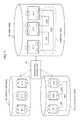
- FIG. 7 illustrates information stored in the hierarchical control unit 104 when there is a full-mesh-like potential link request between the three nodes N 11 , N 12 , and N 13 in the multilayer network illustrated in FIG. 5 .
- the hierarchical control unit 104 stores information about upper layer nodes and information about potential links that can be connected between the nodes into the user NWDB 101 .
- the user NWDB 101 stores the nodes N 11 to N 13 , virtual ports P 801 to P 806 indicated by circles in dotted lines at the respective nodes, and the potential links L 901 to L 903 indicated by dotted lines.
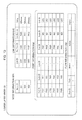
- FIG. 8 illustrates a specific data structure of the user NWDB 101 in the multilayer network in FIG. 5 .
- topology information including node information 101 A, port information 101 B, and link information 101 C is registered in the user NWDB 101 .
- the node information 101 A indicates identification information of each node.
- “Assigned” in the port information 101 B is information indicating whether a port is a “virtual port,” and TRUE indicates a real port rather than a virtual port, and FALSE indicates a virtual port.
- “Established” in the link information 101 C is information indicating whether a link is a potential link, and TRUE indicates a set link for which a flow is actually set to the lower layer network, and FALSE indicates a potential link.
- a sum of a link delay on a route calculated at creation of each potential link by the hierarchical control unit 104 is registered as metric information in “Delay” of a link.
- “Delay” indicates a link delay generated when setting a lower layer flow to the section to create a link.
- FIGS. 9 and 10 illustrate topology information about the upper layer NWDB 102 and the lower layer NWDB 103 at creation of the user NWDB 101 . Since a flow does not exist in the lower layer network, a link does not exist in the upper layer NWDB 102 illustrated in FIG. 9 , and only node information 102 A and port information 102 B are registered therein. However, depending on a network configuration, a link connecting ports that are not in layer boundaries may be registered. In this case, topology information about the upper layer NWDB 102 also including the link is copied to the user NWDB 101 .
- Topology information including node information 103 A, port information 103 B, and link information 103 C is registered in the lower layer NWDB 103 illustrated in FIG. 10 .
- delay information (“Delay”) in the link information 103 C is a propagation delay based on a physical distance of a link, and is registered by the lower layer control unit 106 . While no flow is registered in the lower layer NWDB 103 , there may be a case that a flow is registered depending on an initial state of the network. In this case, a potential link creation operation is performed after a set link related to each flow is created.
- FIG. 11 illustrates a data structure of the layer boundary 40 held by the layer boundary information management unit 204 in the hierarchical control unit 104 .
- each port may be added with information about a maximum bandwidth, a remaining bandwidth, and a bandwidth secured for a flow, or may be added with cost information for route calculation as metric information other than a link delay.
- a port may be added with available resource information and unused resource information.
- the resource information relates to a wavelength in a WDM layer, a time slot in a TDM layer, and flow identification information in a header in a packet-switching-based layer (for example, a label in a shim header in MPLS, a virtual local area network (VLAN) identifier (VID) in a VLAN, and a combination of tuples that can be matched in OpenFlow).
- a wavelength in a WDM layer for example, a label in a shim header in MPLS, a virtual local area network (VLAN) identifier (VID) in a VLAN, and a combination of tuples that can be matched in OpenFlow.
- VLAN virtual local area network
- the user request unit 20 refers to topology information in the user NWDB 101 exemplified in FIG. 8 and performs route calculation of a flow to be set, based on a requirement of the flow.
- a flow with a minimum delay between the port P 301 on the node N 11 and the port P 304 on the node N 13 (referring to FIG. 7 ) is requested as the flow requirement.
- FIG. 7 illustrates two routes as candidate routes of a flow from the node N 11 to the node N 13 .
- the candidate routes include a first route (total delay: 200 msec) routed through the links L 901 (delay: 100 msec) and L 902 (delay: 100 msec), and a second route (total delay: 300 msec) routed through the link L 903 (delay: 300 msec).
- the first route has a smaller delay, and therefore the user request unit 20 selects the first route (L 901 and L 902 ).
- Dijkstra's algorithm that treats a delay as a cost of a link may be considered.
- the user request unit 20 registers a flow F 701 including the selected first route (L 901 -L 902 ) in the user NWDB 101 (Step S 401 ).
- FIG. 13 schematically illustrates the flow F 701 in the user NWDB 101 .
- “Status” in flow information 101 D in the user NWDB 101 illustrated in FIG. 14 is set to “setting in progress.”
- the hierarchical control unit 104 checks whether or not a route of the flow F 701 includes a potential link (Step S 402 ).
- the flow F 701 includes two potential links L 901 and L 902 .
- a potential link When a potential link is included (Yes in Step S 402 ), the hierarchical control unit 104 first registers a flow related to a potential link (the potential link L 901 in this case) in the lower layer NWDB 103 (Step S 403 ).
- a lower layer route related to the potential link L 901 is a route following the link L 601 between the nodes N 21 and N 22 . It is assumed in this case that the port P 402 on the node N 21 and the port P 403 on the node N 22 that are included in the layer boundary 40 are selected as endpoints of the flow. Accordingly, as illustrated in FIG.
- the hierarchical control unit 104 registers a flow F 703 having the link L 601 as a route and the ports P 402 and P 403 as endpoints, in the lower layer NWDB 103 . However, at this time, “Status” of the flow F 703 is set to “setting in progress.”
- the lower layer control unit 106 When the flow F 703 is registered in the lower layer NWDB 103 , the lower layer control unit 106 actually sets a flow to each network device in the lower layer network 31 in accordance with information about the registered flow F 703 (Step S 404 ). When the flow setting is completed, as illustrated in FIG. 16 , the lower layer control unit 106 changes “Status” of the flow F 703 in the lower layer NWDB 103 to “set.”
- the hierarchical control unit 104 changes a potential link in the user NWDB 101 related to the set flow F 703 to “set” (Step S 405 ). Specifically, as illustrated in FIG. 14 , “Established” (set) for the potential link L 901 is changed to “TRUE.” Further, association of the endpoints of the potential link L 901 , the virtual ports P 802 and P 803 , with ports in the upper layer NWDB 102 is performed at the same time.
- the endpoint ports of the flow F 703 in the lower layer NWDB 103 are the port P 402 on the node N 21 and the port P 403 on the node N 22 . Consequently, by referring to the layer boundary information illustrated in FIG.
- the inter-DB-information correspondence management unit 205 relates the port P 306 on the node N 11 in the upper layer NWDB 102 to the virtual port P 802 in the user NWDB 101 .
- the inter-DB-information correspondence management unit 205 further relates the port P 307 on the node N 12 in the upper layer NWDB 102 to the virtual port P 803 in the user NWDB 101 , and holds correspondences between the ports.
- the virtual network information management unit 203 in the hierarchical control unit 104 changes “Assigned” for the virtual ports P 802 and P 803 in the port information 101 B in the user NWDB 101 to “TRUE,” respectively.
- the hierarchical control unit 104 registers the link in the user NWDB 101 , being changed to “set” in Step S 405 , in the upper layer NWDB 102 as a link (Step S 406 ). Specifically, the hierarchical control unit 104 registers a link L 001 related to the link L 901 in the user NWDB 101 , between the ports P 306 and P 307 in the upper layer NWDB 102 , based on the previously held inter-DB-information correspondence. At that time, another type of information about the link such as a delay is also copied. Further, the inter-DB-information correspondence management unit 205 also holds a correspondence between the link L 901 in the user NWDB 101 and the link L 001 in the upper layer NWDB 102 as an inter-DB-information correspondence.
- the hierarchical control unit 104 recalculates a potential link (Step S 407 ). Specifically, out of the nodes in the upper layer network 32 , a node in which a link is set to every port in the layer boundary by the previous link and flow setting is excluded from virtual port creation target nodes in the user NWDB 101 . Consequently, a virtual port and a potential link of the excluded node are also deleted from the user NWDB 101 . By contrast, when there is a node on which a virtual port does not exist in the user NWDB 101 despite including a port in the layer boundary to which a link is not set in the upper layer, a virtual port and a potential link are added.
- a virtual port is added to every virtual port creation target node including the node, and a potential link is created by an operation similar to Step S 303 in FIG. 6 .
- the potential link reallocation eliminates a potential link passing a flow registered in the user NWDB 101 , a setting failure of the flow occurs, and therefore the “Status” information of the flow is changed to “setting failure.”
- the user request unit 20 resets the flow to another route by using the topology information in the user NWDB 101 .
- the hierarchical control unit 104 performs Steps S 403 to S 407 described above on every potential link through which the first flow registered in the user NWDB 101 is routed (Step S 408 ). As described above, processing on the potential link L 901 out of the two potential links L 901 and L 902 that are included in the flow F 701 is completed, but the potential link L 902 still remains (No in Step S 408 ). Accordingly, the hierarchical control unit 104 performs Steps S 403 to S 407 described above on the potential link L 902 .
- the hierarchical control unit 104 copies information about the flow registered in the user NWDB 101 to the upper layer NWDB 102 (Step S 409 ).
- “Status” of the flow F 702 indicated in FIG. 15 is set to “setting in progress.”
- the upper layer control unit 105 When the flow is registered in the upper layer NWDB 102 , the upper layer control unit 105 actually sets the flow to each network device in the upper layer network 32 in accordance with the registered information about the flow F 702 (Step S 410 ).
- the upper layer control unit 105 changes the “Status” information of the flow F 702 in the upper layer NWDB 102 to “set” as illustrated in FIG. 15 .
- the hierarchical control unit 104 changes “Status” of the flow F 701 in the user NWDB 101 to “set” as illustrated in FIG. 14 .
- the user request unit 20 is able to become aware of the flow setting completion by the flow information change in the user NWDB 101 .
- the hierarchical control unit 104 performs required flow setting on the lower layer network 31 and the upper layer network 32 as illustrated in FIG. 13 .
- the data structures of the user NWDB 101 , the upper layer NWDB 102 , and the lower layer NWDB 103 that are illustrated in FIG. 13 are exemplified in FIGS. 14, 15, and 16 , respectively.
- the flow information 101 D is added in addition to the topology information ( 101 A, 101 B, and 101 C). Further, “Established” information of a set link is set to “TRUE,” and “Assigned” information of a port associated with a port in the upper layer network is set to “TRUE.” Thus, when a flow is added to the user NWDB 101 , the network control device 10 performs required setting on the lower layer network 31 and the upper layer network 32 , respectively.
- links L 001 and L 002 are added as a result of a flow being set to the lower layer network 31 . Further, information about the set flow is also added.
- flow information 103 D is added in addition to the topology information ( 103 A, 103 B, and 103 C).
- “Path” holds route information about the flow in a form of a list of a link through which the flow is routed.
- “Match” holds information about a node and a port at the input side endpoint of the flow
- “Action” holds information about a node and a port at the output side endpoint of the flow.
- the first example embodiment of the present invention creates a potential link in the user NWDB 101 and enters information, such as a delay, anticipated when a flow is set to the lower layer.
- a user is able to determine a route satisfying a requirement of a flow to be set, and perform path setting, considering link addition.
- path setting considering link addition to a section without a link in the lower layer network 31 can be performed.
- a network control device has a configuration similar to that of the network control device according to the first example embodiment. A difference in operation between the network control device according to the present example embodiment and the network control device according to the first example embodiment will be described below.
- the network control device performs an operation illustrated in FIG. 17 , in addition to the operation described in the first example embodiment.
- the virtual network information management unit 203 periodically updates potential link information (Step S 502 ). Processing performed in Step S 502 is equivalent to Step S 302 according to the first example embodiment.
- the virtual network information management unit 203 notifies most recent potential link information to the user NWDB 101 (Step S 503 ). Processing performed in Step S 503 is equivalent to Step S 303 according to the first example embodiment.
- Time intervals at which these Steps are repeatedly performed are determined by the path calculation scheduler 301 .
- the time interval may be determined in a fixed or dynamic manner, based on a preprogrammed value, or a preset or predesignated value, or may be determined in consideration of load status and the like of the network control device 10 . Further, a time, a period of time, or information used for derivation thereof may be provided as a parameter of a potential link request created in Step S 302 , and the time interval may be determined based on the information.
- the second example embodiment of the present invention is able to continue updating potential link information recorded in the user NWDB 101 . Consequently, the effect according to the first example embodiment can be sustained.
- a network control device has a configuration similar to the configurations of the network control devices according to the first and second example embodiments. A difference in operation between the present example embodiment and the first and second example embodiments will only be described.
- the virtual network information management unit 203 detects a state change in either layer of the network being the upper layer network 32 or the lower layer network 31 , through the upper layer NWDB 102 or the lower layer NWDB 103 (Step S 601 ).
- the detection is performed by a callback or a message notification from the upper layer NWDB 102 or the lower layer NWDB 103 to the external DB access unit 202 .
- the detection is performed by polling to the upper layer NWDB 102 or the lower layer NWDB 103 by the external DB access unit 202 .
- Step S 602 the virtual network information management unit 203 updates potential link information and notifies most recent potential link information to the user NWDB 101 (Step S 602 ). Processing performed in Step S 602 is equivalent to Step S 502 according to the second example embodiment.
- Step S 603 a potential link in the user NWDB 101 is updated by the potential link notified by the virtual network information management unit 203 (Step S 603 ). Processing performed in Step S 603 is equivalent to Step S 503 according to the second example embodiment.
- the third example embodiment of the present invention is able to immediately update potential link information recorded in the user NWDB 101 , in accordance with a state change of the upper layer network 32 or the lower layer network 31 not caused by the network control device 10 . Consequently, connectivity of a potential link recorded in the user NWDB 101 can be maintained.
- the cause other than the network control device 10 includes a failure, control from another system, setting change, and equipment work.
- a network control device has a configuration similar to the configurations of the network control devices according to the first to third example embodiments. A difference in operation between the present example embodiment and the first to third example embodiments will be described.
- a user is able to update a potential link request in the user NWDB 101 through the user request unit 20 at any timing. Consequently, potential link request information in the user NWDB 101 is updated.
- the virtual network information management unit 203 detects the update through an operation similar to Step S 302 according to the first example embodiment. Then, the virtual network information management unit 203 updates potential link information through an operation similar to Step S 502 according to the second example embodiment, and notifies most recent potential link information to the user NWDB 101 .
- the user NWDB 101 is updated by the notified most recent potential link information through an operation similar to Step S 503 according to the second example embodiment.
- the user When a user adds a potential link request, the user adds the potential link request to the user NWDB 101 through the user request unit 20 at any timing.
- An operation after the potential link request is added follows the operation according to the first example embodiment.
- the user When a user deletes a potential link request, the user deletes the potential link request from the user NWDB 101 through the user request unit 20 at any timing. An operation after the potential link request is deleted follows the operation in and after Step S 602 according to the third example embodiment. Alternatively, the user NWDB 101 may manage the potential link request by soft state.
- the user NWDB 101 holds a timer for each potential link request and, when a predetermined time elapses from the start of a timer, deletes the potential link information.
- the timer is reset.
- the fourth example embodiment of the present invention enables a user to always convey a change of request with respect to a potential link to the network control device 10 through the user NWDB 101 .
- a network control device handles a three-layered network as a control target. It is assumed that the three layers are referred to as a first layer, a second layer, and a third layer, in an ascending order from the lowest layer.
- a network control device 50 controls first to third layer networks 33 to 35 in accordance with a flow request by a user from a user request unit 20 .
- the network control device 50 includes first and second hierarchical control units 5101 and 5102 , first and second user NWDBs 5201 and 5202 , first to third layer NWDBs 5301 to 5303 , and first to third layer control units 5401 to 5403 .
- the first user NWDB 5201 is a user NWDB of the first hierarchical control unit 5101 and also a lower layer NWDB of the second hierarchical control unit 5102 .
- the second user NWDB 5202 is a user NWDB of the second hierarchical control unit 5102 .
- the first layer NWDB 5301 is a lower layer NWDB of the first hierarchical control unit 5101 and holds network information about a first layer network 33 .
- the second layer NWDB 5302 is an upper layer NWDB of the first hierarchical control unit 5101 and holds network information about a second layer network 34 .
- the third layer NWDB 5303 is an upper layer NWDB of the second hierarchical control unit 5102 and holds network information about a third layer network 35 .
- the first to third layer control units 5401 to 5403 control the first to third layer networks 33 to 35 , respectively, in accordance with respective information changes in the first to third layer NWDBs 5301 to 5303 .
- first to third layer control units 5401 to 5403 in the network control device 50 acquire network information from the first to third layer networks 33 to 35 , respectively. It is further assumed that the first to third layer control units 5401 to 5403 register information about a node, a port, and a link in the first to third layer NWDBs 5301 to 5303 , respectively. It is further assumed that information about a layer boundary between the first layer and the second layer, and information about a layer boundary between the second layer and the third layer are set to the first hierarchical control unit 5101 and the second hierarchical control unit 5102 , respectively.
- the first hierarchical control unit 5101 creates information in the first user NWDB 5201 with the first layer NWDB 5301 as a lower layer NWDB and the second layer NWDB 5302 as an upper layer NWDB (Step S 5501 ).
- the specific generation operation is similar to the operation according to the first example embodiment illustrated in FIG. 6 .
- the second hierarchical control unit 5102 creates information in the second user NWDB 5202 with the first user NWDB 5201 as a lower layer NWDB and the third layer NWDB 5303 as an upper layer NWDB (Step S 5502 ).
- the specific generation operation is similar to the operation according to the first example embodiment illustrated in FIG. 6 .
- the information creation in the first and second user NWDBs 5201 and 5202 is completed.
- the user request unit 20 refers to topology information in the second user NWDB 5202 , performs route calculation of a flow to be set, based on a requirement of the flow, and registers the flow in the second user NWDB 5202 (Step S 5601 ).
- the specific operation is similar to Step S 401 in FIG. 12 .
- the second hierarchical control unit 5102 checks whether or not a route of the registered flow includes a potential link (Step S 5602 ). When a potential link is included (Yes in Step S 5602 ), the second hierarchical control unit 5102 registers the flow related to the potential link in the first user NWDB 5201 corresponding to a lower layer NWDB with respect to the second hierarchical control unit 5102 (Step S 5603 ).
- Step S 402 in FIG. 12 The specific operation is similar to Step S 402 in FIG. 12 .
- the first hierarchical control unit 5101 checks whether or not a route of the registered flow includes a potential link (Step S 5604 ).
- a potential link is included (Yes in Step S 5604 )
- flow registration in the first layer NWDB 5301 by the first hierarchical control unit 5101 and flow setting by the first layer control unit 5401 are performed.
- link information change in the first user NWDB 5201 and link information change in the second layer NWDB 5302 are performed by the first hierarchical control unit 5101 (Step S 5605 ).
- the specific operations are similar to the first example embodiment, that is, the operations in Steps S 403 to S 408 (Yes) in FIG. 12 .
- Step S 5605 After completion of Step S 5605 or when a potential link is not included (No in Step S 5604 ), flow information about the flow registered in the first user NWDB 5201 is copied to the second layer NWDB 5302 by the first hierarchical control unit 5101 . Additionally, flow setting to the second layer network 34 by the second layer control unit 5402 is performed (Step S 5606 ). Specific operations are similar to the first example embodiment, that is, Steps S 409 and S 410 in FIG. 12 .
- Step S 5606 completes the flow setting to the first user NWDB 5201 being a lower layer NWDB of the second hierarchical control unit 5102 . Consequently, the second hierarchical control unit 5102 performs change of a potential link in the second user NWDB 5202 to a set link and link information registration in the third layer NWDB 5303 (Step S 5607 ).
- the specific operations are similar to the operations according to the first example embodiment, and are equivalent to Steps S 405 to S 407 in FIG. 12 .
- Step S 5607 After completion of Step S 5607 or when a route of a registered flow does not include a potential link (No in Step S 5602 ), the second hierarchical control unit 5102 registers the flow registered in Step S 5601 in the third layer NWDB 5303 . Additionally, the third layer control unit 5403 sets the flow to the third layer network 35 (Step S 5608 ).
- the network control device 50 when a flow is added to the second user NWDB 5202 , the network control device 50 performs required setting to the networks 33 to 35 in the first layer, the second layer, and the third layer, respectively.
- a multilayer network with three layers or more may be similarly controlled by the network control device including [(number of layers)—1] pieces of hierarchical control units.
- a Path Computation Element Communication Protocol (PCEP) message in which a predetermined value is set to a predetermined field may be used.
- PCEP Path Computation Element Communication Protocol
- at least one of the layers may have more than one networks.
- a storage means holding a policy related to disclosure of a potential link to each upper layer may be provided. At this time, input to path calculation and/or potential link information notified to each upper layer is changed in accordance with the policy. Such a configuration enables flexible control of the respective plurality of upper layers in accordance with the policy.
- the present invention is applicable to a service by which a carrier promptly provides a virtual network for a user on an on-demand basis.
- the present invention is applicable to a network control part of a virtual private network (VPN) service connecting base networks of a user, and a cloud service connecting a data center and a user base, or data centers, and the like.
- VPN virtual private network
- the performance includes at least one of a bandwidth, a delay, reliability, and priority of the link.
- the hierarchical control unit obtains the link and the performance, based on topology information about a layer boundary between the upper layer network and the lower layer network, and topology information about the lower layer network.
- the hierarchical control unit obtains a route of the flow, based on topology information about the upper layer network, and the link.
- the hierarchical control unit periodically performs an operation of obtaining the link and the performance, and holding the link and the performance in an associated manner.
- the hierarchical control unit performs an operation of obtaining the link and the performance, and holding the link and the performance in an associated manner, when a state of at least either network of the upper layer network or the lower layer network changes.
- a network control device that applies a network control operation by the network control device according to any one of supplementary notes 1 to 6 to at least one set of two networks of neighboring layers out of a plurality of networks in a hierarchy with three levels or more.
- the performance includes at least one item of a bandwidth, a delay, reliability, and priority of the link.
- the network control device obtains the link and the performance, based on topology information about a layer boundary between the upper layer network and the lower layer network, and topology information about the lower layer network.
- the network control method according to any one of supplementary notes 8 to 10, further including, by the network control device,
- a step of obtaining a route of the flow based on topology information about the upper layer network, and the link.
- the network control device periodically performs an operation of obtaining the link and the performance, and holding the link and the performance in an associated manner.
- the network control device performs an operation of obtaining the link and the performance, and holding the link and the performance in an associated manner, when a state of at least either network of the upper layer network or the lower layer network changes.
- a network control method including, by the network control device,
- the performance includes at least one of a bandwidth, a delay, reliability, and priority of the link.
- processing of obtaining the link and the performance based on topology information about a layer boundary between the upper layer network and the lower layer network, and topology information about the lower layer network.
- processing of obtaining a route of the flow based on topology information about the upper layer network, and the link.
- a program causing the computer to perform
Landscapes
- Engineering & Computer Science (AREA)
- Computer Networks & Wireless Communication (AREA)
- Signal Processing (AREA)
- Data Exchanges In Wide-Area Networks (AREA)
Applications Claiming Priority (3)
| Application Number | Priority Date | Filing Date | Title |
|---|---|---|---|
| JP2015-044737 | 2015-03-06 | ||
| JP2015044737 | 2015-03-06 | ||
| PCT/JP2016/001150 WO2016143310A1 (fr) | 2015-03-06 | 2016-03-03 | Dispositif de commande de réseau, procédé de commande de réseau et support d'enregistrement pour programme |
Publications (2)
| Publication Number | Publication Date |
|---|---|
| US20180062982A1 US20180062982A1 (en) | 2018-03-01 |
| US10313232B2 true US10313232B2 (en) | 2019-06-04 |
Family
ID=56879461
Family Applications (1)
| Application Number | Title | Priority Date | Filing Date |
|---|---|---|---|
| US15/555,324 Active US10313232B2 (en) | 2015-03-06 | 2016-03-03 | Network control device, network control method, and recording medium for program |
Country Status (3)
| Country | Link |
|---|---|
| US (1) | US10313232B2 (fr) |
| JP (1) | JP6733655B2 (fr) |
| WO (1) | WO2016143310A1 (fr) |
Cited By (1)
| Publication number | Priority date | Publication date | Assignee | Title |
|---|---|---|---|---|
| US11093363B2 (en) * | 2019-01-08 | 2021-08-17 | Fujifilm Business Innovation Corp. | Information processing apparatus for allocating bandwidth based on priority and non-transitory computer readable medium |
Families Citing this family (3)
| Publication number | Priority date | Publication date | Assignee | Title |
|---|---|---|---|---|
| JP6863305B2 (ja) * | 2018-01-29 | 2021-04-21 | オムロン株式会社 | ネットワークシステム、制御方法および制御装置 |
| CN113300928B (zh) * | 2020-02-21 | 2023-01-13 | 华为技术有限公司 | 一种传输业务报文的方法、设备和系统 |
| WO2022176043A1 (fr) * | 2021-02-17 | 2022-08-25 | 日本電信電話株式会社 | Dispositif et procédé de commande de sélection de trajet, et programme |
Citations (11)
| Publication number | Priority date | Publication date | Assignee | Title |
|---|---|---|---|---|
| JPH1070571A (ja) | 1996-06-20 | 1998-03-10 | Internatl Business Mach Corp <Ibm> | 最適パス決定方法 |
| JP2006013926A (ja) | 2004-06-25 | 2006-01-12 | Nippon Telegr & Teleph Corp <Ntt> | トラヒック情報処理方法、トラヒック情報処理プログラム、および、トラヒック情報処理装置 |
| JP2007530967A (ja) | 2004-03-31 | 2007-11-01 | ブリティッシュ・テレコミュニケーションズ・パブリック・リミテッド・カンパニー | 経路探索システム |
| JP2008211551A (ja) | 2007-02-27 | 2008-09-11 | Nippon Telegr & Teleph Corp <Ntt> | 仮想トポロジ設計装置および仮想トポロジ設計方法 |
| US20090323708A1 (en) * | 2005-10-06 | 2009-12-31 | Markus Ihle | Subscriber and Communication Controller of a communication System and Method for Implementing a Gateway Functionality in a Subscriber of a Communication System |
| US20100287273A1 (en) * | 2009-05-05 | 2010-11-11 | Motorola, Inc. | System and method for directing communications within a heterogeneous network environment |
| US20110032833A1 (en) * | 2009-08-07 | 2011-02-10 | Microsoft Corporation | Optimization of traffic routing for data center services |
| US7889675B2 (en) | 2003-01-31 | 2011-02-15 | Tellabs Operations, Inc. | Method and system for multi-layer network routing |
| US20130089005A1 (en) * | 2011-10-07 | 2013-04-11 | Futurewei Technologies, Co. | Simple Topology Transparent Zoning in Network Communications |
| US20130117443A1 (en) * | 2010-10-30 | 2013-05-09 | Huawei Technologies Co., Ltd. | Method, apparatus and system for joint optimization |
| WO2014054691A1 (fr) | 2012-10-03 | 2014-04-10 | 日本電気株式会社 | Programme, procédé de commande, appareil de commande et système de communication |
-
2016
- 2016-03-03 WO PCT/JP2016/001150 patent/WO2016143310A1/fr not_active Ceased
- 2016-03-03 US US15/555,324 patent/US10313232B2/en active Active
- 2016-03-03 JP JP2017504859A patent/JP6733655B2/ja active Active
Patent Citations (14)
| Publication number | Priority date | Publication date | Assignee | Title |
|---|---|---|---|---|
| JPH1070571A (ja) | 1996-06-20 | 1998-03-10 | Internatl Business Mach Corp <Ibm> | 最適パス決定方法 |
| US6400681B1 (en) | 1996-06-20 | 2002-06-04 | Cisco Technology, Inc. | Method and system for minimizing the connection set up time in high speed packet switching networks |
| US7889675B2 (en) | 2003-01-31 | 2011-02-15 | Tellabs Operations, Inc. | Method and system for multi-layer network routing |
| JP2007530967A (ja) | 2004-03-31 | 2007-11-01 | ブリティッシュ・テレコミュニケーションズ・パブリック・リミテッド・カンパニー | 経路探索システム |
| US20070276709A1 (en) | 2004-03-31 | 2007-11-29 | Trimby Martin W | Pathfinding System |
| JP2006013926A (ja) | 2004-06-25 | 2006-01-12 | Nippon Telegr & Teleph Corp <Ntt> | トラヒック情報処理方法、トラヒック情報処理プログラム、および、トラヒック情報処理装置 |
| US20090323708A1 (en) * | 2005-10-06 | 2009-12-31 | Markus Ihle | Subscriber and Communication Controller of a communication System and Method for Implementing a Gateway Functionality in a Subscriber of a Communication System |
| JP2008211551A (ja) | 2007-02-27 | 2008-09-11 | Nippon Telegr & Teleph Corp <Ntt> | 仮想トポロジ設計装置および仮想トポロジ設計方法 |
| US20100287273A1 (en) * | 2009-05-05 | 2010-11-11 | Motorola, Inc. | System and method for directing communications within a heterogeneous network environment |
| US20110032833A1 (en) * | 2009-08-07 | 2011-02-10 | Microsoft Corporation | Optimization of traffic routing for data center services |
| US20130117443A1 (en) * | 2010-10-30 | 2013-05-09 | Huawei Technologies Co., Ltd. | Method, apparatus and system for joint optimization |
| US20130089005A1 (en) * | 2011-10-07 | 2013-04-11 | Futurewei Technologies, Co. | Simple Topology Transparent Zoning in Network Communications |
| WO2014054691A1 (fr) | 2012-10-03 | 2014-04-10 | 日本電気株式会社 | Programme, procédé de commande, appareil de commande et système de communication |
| US20150263939A1 (en) | 2012-10-03 | 2015-09-17 | Nec Corporation | Communication system, control apparatus, control method and program |
Non-Patent Citations (4)
| Title |
|---|
| Iizawa et al. "Dynamic Multi-layer Path control Using Virutal Links," Proceedings of the 2014 IEICE General Conference Communications 2, Mar. 21, 2014, p. 162. |
| Iizawa et al., "Special Issue on SDN for Advancing ICT Systems: Multilayer Abstraction Technology Providing Integrated Control Platform for Heterogeneous Networks," NEC Technical Journal, Feb. 1, 2014, vol. 66, No. 2, pp. 44-47. |
| International Search Report for PCT/JP2016/001150, dated May 24, 2016 (PCT/ISA/210). |
| Written Opinion of the International Searching Authority for PCT/JP2016/001150, dated May 24, 2016 (PCT/ISA/237). |
Cited By (1)
| Publication number | Priority date | Publication date | Assignee | Title |
|---|---|---|---|---|
| US11093363B2 (en) * | 2019-01-08 | 2021-08-17 | Fujifilm Business Innovation Corp. | Information processing apparatus for allocating bandwidth based on priority and non-transitory computer readable medium |
Also Published As
| Publication number | Publication date |
|---|---|
| US20180062982A1 (en) | 2018-03-01 |
| JP6733655B2 (ja) | 2020-08-05 |
| JPWO2016143310A1 (ja) | 2017-12-21 |
| WO2016143310A1 (fr) | 2016-09-15 |
Similar Documents
| Publication | Publication Date | Title |
|---|---|---|
| US10237202B2 (en) | Network control device, network control method, and recording medium for program | |
| US9444712B2 (en) | Bandwidth on-demand services in multiple layer networks | |
| ES2614863T3 (es) | Control de servicio en nube informática y arquitectura de gestión extendida para conectarse al estrato de red | |
| JP5919046B2 (ja) | パス計算方法 | |
| US9559944B2 (en) | Method and related apparatus for establishing link-diverse traffic paths in a telecommunications network | |
| EP1395003A2 (fr) | Procédé de routage selon le plus court chemin à base de contraintes pour des réseaux optiques de transport commutés dynamiquement | |
| JP2014103656A (ja) | ネットワークシステム及びルーティング方法 | |
| US10904130B2 (en) | Method for scalable computer network partitioning | |
| US10313232B2 (en) | Network control device, network control method, and recording medium for program | |
| CN110086715B (zh) | 网络路径计算方法、装置和系统 | |
| US20160241469A1 (en) | Multi-layer network control method and device | |
| CN102264009B (zh) | 虚拟路径获取方法、相关装置及网络系统 | |
| CN107078954B (zh) | 用于计算机网络中的端点标识的方法 | |
| CN106487682B (zh) | 一种Diameter信令网路由方法和装置 | |
| CN108390780B (zh) | 用于处理信息的方法和装置 | |
| JP6418167B2 (ja) | ネットワーク制御装置、ネットワークシステム、ネットワーク制御方法、および、プログラム |
Legal Events
| Date | Code | Title | Description |
|---|---|---|---|
| AS | Assignment |
Owner name: NEC CORPORATION, JAPAN Free format text: ASSIGNMENT OF ASSIGNORS INTEREST;ASSIGNOR:ISHIDA, SHINYA;REEL/FRAME:043473/0864 Effective date: 20170804 |
|
| FEPP | Fee payment procedure |
Free format text: ENTITY STATUS SET TO UNDISCOUNTED (ORIGINAL EVENT CODE: BIG.); ENTITY STATUS OF PATENT OWNER: LARGE ENTITY |
|
| STPP | Information on status: patent application and granting procedure in general |
Free format text: NOTICE OF ALLOWANCE MAILED -- APPLICATION RECEIVED IN OFFICE OF PUBLICATIONS |
|
| STPP | Information on status: patent application and granting procedure in general |
Free format text: PUBLICATIONS -- ISSUE FEE PAYMENT VERIFIED |
|
| STCF | Information on status: patent grant |
Free format text: PATENTED CASE |
|
| MAFP | Maintenance fee payment |
Free format text: PAYMENT OF MAINTENANCE FEE, 4TH YEAR, LARGE ENTITY (ORIGINAL EVENT CODE: M1551); ENTITY STATUS OF PATENT OWNER: LARGE ENTITY Year of fee payment: 4 |
|
| AS | Assignment |
Owner name: NEC ASIA PACIFIC PTE LTD., SINGAPORE Free format text: ASSIGNMENT OF ASSIGNORS INTEREST;ASSIGNOR:NEC CORPORATION;REEL/FRAME:066867/0886 Effective date: 20240313 |