WO2016143310A1 - Dispositif de commande de réseau, procédé de commande de réseau et support d'enregistrement pour programme - Google Patents
Dispositif de commande de réseau, procédé de commande de réseau et support d'enregistrement pour programme Download PDFInfo
- Publication number
- WO2016143310A1 WO2016143310A1 PCT/JP2016/001150 JP2016001150W WO2016143310A1 WO 2016143310 A1 WO2016143310 A1 WO 2016143310A1 JP 2016001150 W JP2016001150 W JP 2016001150W WO 2016143310 A1 WO2016143310 A1 WO 2016143310A1
- Authority
- WO
- WIPO (PCT)
- Prior art keywords
- link
- network
- nwdb
- flow
- information
- Prior art date
- Legal status (The legal status is an assumption and is not a legal conclusion. Google has not performed a legal analysis and makes no representation as to the accuracy of the status listed.)
- Ceased
Links
Images



Classifications
-
- H—ELECTRICITY
- H04—ELECTRIC COMMUNICATION TECHNIQUE
- H04L—TRANSMISSION OF DIGITAL INFORMATION, e.g. TELEGRAPHIC COMMUNICATION
- H04L45/00—Routing or path finding of packets in data switching networks
- H04L45/38—Flow based routing
-
- H—ELECTRICITY
- H04—ELECTRIC COMMUNICATION TECHNIQUE
- H04L—TRANSMISSION OF DIGITAL INFORMATION, e.g. TELEGRAPHIC COMMUNICATION
- H04L41/00—Arrangements for maintenance, administration or management of data switching networks, e.g. of packet switching networks
- H04L41/12—Discovery or management of network topologies
-
- H—ELECTRICITY
- H04—ELECTRIC COMMUNICATION TECHNIQUE
- H04L—TRANSMISSION OF DIGITAL INFORMATION, e.g. TELEGRAPHIC COMMUNICATION
- H04L41/00—Arrangements for maintenance, administration or management of data switching networks, e.g. of packet switching networks
- H04L41/40—Arrangements for maintenance, administration or management of data switching networks, e.g. of packet switching networks using virtualisation of network functions or resources, e.g. SDN or NFV entities
-
- H—ELECTRICITY
- H04—ELECTRIC COMMUNICATION TECHNIQUE
- H04L—TRANSMISSION OF DIGITAL INFORMATION, e.g. TELEGRAPHIC COMMUNICATION
- H04L45/00—Routing or path finding of packets in data switching networks
- H04L45/02—Topology update or discovery
- H04L45/04—Interdomain routing, e.g. hierarchical routing
-
- H—ELECTRICITY
- H04—ELECTRIC COMMUNICATION TECHNIQUE
- H04L—TRANSMISSION OF DIGITAL INFORMATION, e.g. TELEGRAPHIC COMMUNICATION
- H04L45/00—Routing or path finding of packets in data switching networks
- H04L45/12—Shortest path evaluation
- H04L45/123—Evaluation of link metrics
-
- H—ELECTRICITY
- H04—ELECTRIC COMMUNICATION TECHNIQUE
- H04L—TRANSMISSION OF DIGITAL INFORMATION, e.g. TELEGRAPHIC COMMUNICATION
- H04L45/00—Routing or path finding of packets in data switching networks
- H04L45/64—Routing or path finding of packets in data switching networks using an overlay routing layer
-
- H—ELECTRICITY
- H04—ELECTRIC COMMUNICATION TECHNIQUE
- H04L—TRANSMISSION OF DIGITAL INFORMATION, e.g. TELEGRAPHIC COMMUNICATION
- H04L47/00—Traffic control in data switching networks
- H04L47/10—Flow control; Congestion control
- H04L47/19—Flow control; Congestion control at layers above the network layer
-
- H—ELECTRICITY
- H04—ELECTRIC COMMUNICATION TECHNIQUE
- H04L—TRANSMISSION OF DIGITAL INFORMATION, e.g. TELEGRAPHIC COMMUNICATION
- H04L45/00—Routing or path finding of packets in data switching networks
- H04L45/12—Shortest path evaluation
- H04L45/121—Shortest path evaluation by minimising delays
-
- H—ELECTRICITY
- H04—ELECTRIC COMMUNICATION TECHNIQUE
- H04L—TRANSMISSION OF DIGITAL INFORMATION, e.g. TELEGRAPHIC COMMUNICATION
- H04L45/00—Routing or path finding of packets in data switching networks
- H04L45/12—Shortest path evaluation
- H04L45/125—Shortest path evaluation based on throughput or bandwidth
-
- H—ELECTRICITY
- H04—ELECTRIC COMMUNICATION TECHNIQUE
- H04L—TRANSMISSION OF DIGITAL INFORMATION, e.g. TELEGRAPHIC COMMUNICATION
- H04L45/00—Routing or path finding of packets in data switching networks
- H04L45/302—Route determination based on requested QoS
Definitions
- the present invention relates to a network control device, a network control method, and a program, and more particularly, to a control technology and a design technology for a multi-layer network and a multi-domain network.
- the communication carrier network is composed of a plurality of layers (network layers). For example, a network in which a packet layer that can efficiently use network resources by a statistical multiplexing effect and an optical layer that is suitable for long-distance and large-capacity transmission has been constructed.
- packet layer technologies include, for example, MPLS (Multi-Protocol Label Switching) and MPLS-TP (Multi-Protocol Label Switching-Transport Profile).
- MPLS Multi-Protocol Label Switching
- MPLS-TP Multi-Protocol Label Switching-Transport Profile
- the optical layer is generally a circuit-switched network, and OTN (Optical Transport Network) is known as a representative technique.
- the OTN is further divided into TDM (Time Division Division Multiplexing) and WDM (Wavelength Division Division Multiplexing) layers depending on the path switching method. In general, these networks are independently controlled for each layer.
- Patent Document 1 discloses a multi-layer path control technique based on intensive topology design in a packet and WDM two-layer network.
- Patent Document 2 describes a method of abstracting path information that can be set in a lower layer in the form of a node or a link and advertising it using an upper layer routing protocol so that an optimum path can be set. Has been.
- Patent Document 3 the measurement result of the traffic amount flowing in the upper path (the logical path of the packet network) is acquired in the multilayer network composed of the packet network and the circuit switching network. Then, the routes of the circuit-switched network and the packet network are calculated, and when congestion occurs due to traffic concentration on some lower links, a route that avoids the lower links is calculated.
- Patent Document 4 describes a technique for establishing a connection between an origin node and a destination node in a short time
- Patent Document 5 discloses a technique for generating a new route for a destination node. Are listed.
- paths and links have a nested configuration. That is, in a lower layer network, a path is set by using lower layer nodes, ports, and links as network resources. In the upper layer network, the path set in the lower layer is treated as a link between nodes, and the node and port information added to it becomes the upper layer network resource. Set.
- the path information that can be set in the lower layer is abstracted in the form of a node or link and advertised by the routing protocol of the higher layer, the optimum path is set even in such a case. It becomes possible to do.
- the advertised lower layer resource information is included, if the upper layer path that satisfies the requirements such as bandwidth and delay cannot be calculated, the path setting fails. become. This is because the path requirement required in the upper layer is not properly transmitted to the lower layer.
- An object of the present invention is to provide a network control device, a network control method, and a program that contribute to the solution of the problem.
- the network control device includes a database that accepts a request for connecting ports of nodes included in an upper layer network, a link that connects the ports via a lower layer network, and the link And a hierarchical control unit that obtains performance and associates and holds the performance.
- the database is a flow between nodes included in the upper layer network, and receives a flow selected according to the link and the performance.
- the hierarchy control unit sets a path corresponding to the link in the lower layer network.
- the network control device accepts a request to connect ports of nodes included in the upper layer network, and connects the ports via the lower layer network. Determining and associating and maintaining a link and the performance of the link, a flow between nodes included in the higher layer network, receiving a flow selected according to the link and the performance, and the flow A path corresponding to the link is set in the lower layer network.
- the program according to the third aspect of the present invention includes a process for receiving a request for connecting ports of nodes included in an upper layer network, a link for connecting the ports via a lower layer network, and the performance of the link.
- a process for obtaining and associating and holding, a process between nodes included in the upper layer network, a process for receiving a flow selected according to the link and the performance, and the link included in the path of the flow If so, a computer is caused to execute a process of setting a path corresponding to the link in the lower layer network.
- the program can also be provided as a program product recorded in a non-transitory computer-readable storage medium.
- the upper layer can receive supply of desired resources from the lower layer.
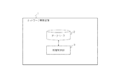
- FIG. 1 is a block diagram illustrating the configuration of a network control device 1 according to an embodiment.
- the network control device 1 includes a database 2 and a hierarchy control unit 3. The operation of one embodiment is illustrated in FIG.
- the database 2 accepts a request to connect the ports of nodes included in the upper layer network (for example, between the ports P802 and P803, between the ports P804 and P805, and between the ports P801 and P806 in FIG. 13).
- the hierarchical control unit 3 obtains and associates the link (for example, links L901 to L903 in FIG. 13) connecting the ports via the lower layer network and the performance of the link (for example, link bandwidth, delay, etc.). Hold.
- the database 2 accepts a flow between nodes included in the upper layer network, which is selected according to the link and the performance.
- the hierarchy control unit 3 sets the flow corresponding to the link in the lower layer network.
- the network control device 1 performs the following procedure when controlling a multi-layer network composed of a plurality of layers of networks. That is, the network control device 1 generates a link in the upper layer network based on the topology information of the lower layer network and the request for connecting the ports of the nodes included in the upper layer network presented by the user.
- a request for connecting ports of nodes included in an upper layer network presented by a user is referred to as a “latent link request”, and a link generated based on the latent link request is referred to as a “latent link”.
- the generated links are, for example, links L901 to L903 in FIG.
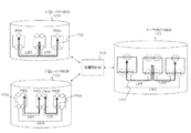
- at least one potential link for example, the potential links L901 and L902 in FIG. 13
- the route for example, the flow F701 in FIG. 13
- the lower layer corresponding to the potential link
- the route (links L601 and L602 in FIG. 13) is set in the lower layer network.
- the upper layer can inform the lower layer of the requirements of the resource (link) desired by itself in advance.
- the upper layer can always be supplied with a desired resource.
- the lower layer can collect resource requirements desired by each individual from a plurality of upper layers, and optimize the resource allocation by performing path design by combining these requirements.
- latent link information that satisfies requirements specified in advance for an upper layer network is provided based on topology information of the lower layer network.
- the upper layer network calculates the path using the topology obtained by adding the latent link information provided from the lower layer to the topology information of the own layer. As a result, it is possible to efficiently design and set a path in consideration of resource information that can be provided from the lower layer to the upper layer.
- multilayer network control as “multilayer control” and using the term “flow” synonymously with “path”.
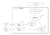
- the network control apparatus 10 controls the lower layer network 31 and the upper layer network 32 in accordance with a flow request from the user request unit 20 by the user.
- the network control device 10 includes a user-oriented network database (NWDB) 101, an upper layer NWDB 102, a lower layer NWDB 103, and a hierarchy control unit 104.
- the network control device 10 includes an upper layer control unit 105 and a lower layer control unit 106.
- the upper layer control unit 105 and the lower layer control unit 106 control the upper layer network 32 and the lower layer network 31 in accordance with respective information changes in the upper layer NWDB 102 and the lower layer NWDB 103.
- a program or a group of programs executed on a computer that plays the role described in the following description may be used. In the following description, a single user will be described, but a plurality of users may exist.
- the NWDB 101 for users is accessed from the user request unit 20 and stores resource information available to the user.
- the upper layer NWDB 102 holds information on the upper layer network 32.
- the lower layer NWDB 103 holds information of the lower layer network 31.
- Each NWDB holds network information including topology information including nodes, ports, and links and flow (path equivalent) information set therein.
- the hierarchy control unit 104 performs control such as conversion to the user NWDB 101 and the upper layer NWDB 102 into a link, generation of a latent link, registration in the user NWDB 101 based on the flow information in the lower layer NWDB 103. .
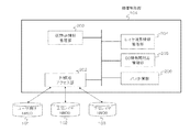
- the hierarchy control unit 104 executes access to the user-oriented NWDB 101, the upper layer NWDB 102, and the lower layer NWDB 103, and acquisition or update of information through the external DB access unit 202. Further, the hierarchy control unit 104 includes a virtual network information management unit 203, a layer boundary information management unit 204, a DB information correspondence management unit 205, and a path calculation unit 206.
- the virtual network information management unit 203 creates latent link information and virtual port information of the NWDB 101 for users and manages those information.
- the layer boundary information management unit 204 manages the layer boundary between the upper layer and the lower layer.
- the DB information correspondence management unit 205 manages the correspondence of information stored in the NWDB 101 for users, the upper layer NWDB 102, and the lower layer NWDB 103.
- the path calculation unit 206 performs path calculation based on the NWDB topology information.
- the virtual network information management unit 203 has a path calculation scheduler 301, a path calculation request DB 302, and a latent link DB 303.
- the path calculation scheduler 301 manages path calculation events.
- the path calculation request DB 302 stores information on latent link requests.
- the latent link DB 303 holds the correspondence between the path and the latent link calculated in response to the latent link request.
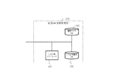
- the hierarchical control unit 104 can also realize an equivalent function by executing a program stored in a memory (not shown) of the network control device 10 on a computer such as a CPU (Central Processing Unit).
- a computer such as a CPU (Central Processing Unit).
- the multi-layer network includes a lower layer network 31, an upper layer network 32, and a layer boundary 40.
- the upper layer network 32 includes nodes N11 to N13 and ports P301 to P310.
- the lower layer network 31 includes nodes N21 to N23, ports P401 to P412, and links L601 to L603.
- the layer boundary 40 has boundary connections B501 to B506.
- the boundary connections B501 to B506 are links that connect ports.
- the boundary connection B501 connects the ports P305 and P401.
- the boundary connection B502 connects the ports P306 and P402.
- the boundary connection B503 connects the ports P307 and P403.
- the boundary connection B504 connects the ports P308 and P404.
- the boundary connection B505 connects the ports P309 and P405.
- a boundary connection B506 connects the ports P310 and P406.
- the upper layer control unit 105 and the lower layer control unit 106 of the network control apparatus 10 obtain information on the upper layer network 32 and information on the lower layer network 31 in FIG. 5 from the respective networks. Furthermore, it is assumed that the upper layer control unit 105 and the lower layer control unit 106 have registered information on nodes, ports, and links in the upper layer NWDB 102 and the lower layer NWDB 103, respectively. Further, it is assumed that the information on the layer boundary 40 is set in advance in the layer boundary information management unit 204 of the hierarchy control unit 104.
- the latent link is created in the NWDB 101 for users, for example.
- the virtual network information management unit 203 of the hierarchy control unit 104 takes in the upper layer topology information from the upper layer NWDB 102 through the external DB access unit 202 and copies it to the user NWDB 101 (step S301). At this time, the port set at the layer boundary 40 is not copied.
- the latent link request describes the requirements for a potential link that is associated with two virtual ports and can connect both virtual ports. Examples of requirements include bandwidth, delay, reliability, priority, and the like.
- the user also creates the virtual ports necessary to create the latent link request. At this time, the user specifies at least the position of the virtual port, that is, the number of nodes and virtual ports with which the virtual port is associated.
- the virtual network information management unit 203 acquires the latent link request added to the user NWDB 101 via the external DB access unit 202. This is performed by a callback or message notification from the user NWDB 101 to the external DB access unit 202. Alternatively, it is performed by polling the NWDB 101 for users by the external DB access unit 202.
- the virtual network information management unit 203 records the acquired latent link request in the path calculation request DB 302.
- the virtual network information management unit 203 checks the connectability of the link connecting the created virtual ports and creates a latent link (step S303).
- the path calculation scheduler 301 generates a path calculation request from the latent link request in the path calculation request DB 302.
- each latent link request recorded in the path calculation request DB 302 in the previous step is read as a path request for connecting two virtual ports with specified requirements.
- These path calculation requests include, in addition to the latent link request added in the previous step, path calculation requests for the latent link requests that have been stored in the user NWDB 101 and the path calculation request DB 302 before that time. It doesn't matter.
- Each path calculation request has information (for example, an identifier of the latent link request) that can uniquely identify the corresponding latent link request.
- the path calculation scheduler 301 determines the time for performing path calculation for these path calculation requests. This time is immediately or after a certain time has elapsed from the present time.
- the elapsed time may be programmed in advance, or may be determined fixedly or dynamically based on a set or designated value. Alternatively, the elapsed time may be determined in consideration of the load status of the network control device 10 and the like. Further, time, time, or information used for deriving these may be assigned as parameters of the latent link request created in step S302, and the elapsed time may be determined based on the information.
- the path calculation scheduler 301 passes a path calculation request to the path calculation unit 206 at a predetermined time.
- the path calculation unit 206 performs path calculation on the path calculation request passed from the path calculation scheduler 301.
- the path calculation unit 206 performs path calculation using a CSPF (Constrained Shortest Path First), a heuristic method such as a genetic method, a mathematical programming method, or other path calculation algorithms.
- the path calculation unit 206 confirms the possibility of connection of a latent link in the path calculation. In confirming the connection possibility, it is confirmed that the upper layer port corresponding to the virtual port designated as the end point of the latent link is physically connected to the lower layer port. This is confirmed with reference to information recorded in the layer boundary information management unit 204.
- the nodes N11 and N12 in FIG. 5 can be connected.
- the port P305 or P306 of the node N11 is connected to the port P401 or P402 of the node N21 by a boundary connection B501 or B502.
- the node N12 is connected to the node N22 by the boundary connection B503 or B504.
- a latent link can be set between the nodes N11 and N12.
- being physically connected means literally physically connected.
- the upper and lower layer ports are physically connected across one or more switchable devices such as a switch, even if both ports are not short-circuited in the same device, the switching control of the same device If the two ports can be short-circuited, it is determined that connection is possible.
- the path calculation unit 206 passes the path calculation result to the virtual network information management unit 203.
- the result of each path calculation has information that can uniquely identify the corresponding path calculation request or the potential link request to which the path calculation request corresponds.
- the virtual network information management unit 203 collates the path calculation result received from the path calculation unit 206 with the latent link request in the path calculation request DB 302. Also, latent link information corresponding to the latent link request is created, and a combination of the link information and the path calculation result is stored in the latent link DB 303.
- the potential link information is information that uniquely identifies the potential link request, and the link specifications (bandwidth, delay, reliability, etc.) when the virtual ports specified in the potential link request are connected by the same path. Performance such as priority).
- the specification of the path may be used as it is, or the specification of the path is processed (the bandwidth value is made smaller than the path bandwidth, the delay value is made larger than the path delay).
- the obtained value may be used.
- the latent link is stored in the latent link DB 303 together with information indicating that no path exists, instead of the path information. Or you may express that a latent link does not exist by not storing this latent link.
- the path calculation scheduler 301 or the latent link DB 303 notifies the user-oriented NWDB 101 of the information on the latent link via the external DB access unit 202 (step S303).
- This notification includes information of the potential link specification and the corresponding potential link request that can be uniquely identified.
- the latent link is recorded in the user NWDB 101 as a link connecting the virtual ports assigned in step S301.
- the user NWDB 101 includes information for determining the difference between the two.
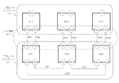
- FIG. 7 shows information stored in the hierarchical control unit 104 when there is a latent link request in a full mesh shape between the three nodes N11, N12, and N13.
- the hierarchical control unit 104 stores information on the upper layer nodes and information on potential links connectable between them in the NWDB 101 for users.
- nodes N11 to N13, virtual ports P801 to P806 indicated by dotted circles at each node, and latent links L901 to L903 indicated by dotted lines are stored in the NWDB 101 for users.
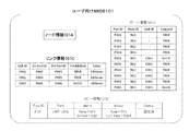
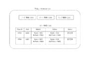
- FIG. 8 shows a specific data structure of the NWDB 101 for users in the multi-layer network of FIG.
- topology information such as node information 101A, port information 101B, and link information 101C is registered in the NWDB 101 for users.
- Node information 101A indicates identification information of each node.
- “Assigned” in the port information 101B is information indicating whether or not the port is a virtual port. If TRUE, the port is not a virtual port but an actual port, and if FALSE, the port is a virtual port.
- “Established” in the link information 101C is information indicating whether the link is a latent link. If TRUE, the link is a set link in which a flow is actually set in the lower layer network. If FALSE, the link is a latent link. It shows that.
- the delay (Delay) represents a link delay that occurs when a link is created by setting a lower layer flow in the section.
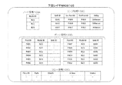
- FIG. 9 and 10 show the topology information of the upper layer NWDB 102 and the lower layer NWDB 103 when the NWDB 101 for users is created.
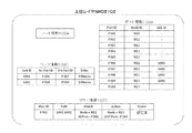
- the upper layer NWDB 102 shown in FIG. 9 since there is no flow in the lower layer network, there is no link and only node information 102A and port information 102B are registered. However, depending on the network configuration, a link connecting ports that are not layer boundaries may be registered. In this case, the topology information of the upper layer NWDB 102 including the link is copied to the user NWDB 101.
- topology information such as node information 103A, port information 103B, and link information 103C is registered.
- the delay information (Delay) of the link information 103C is a propagation delay based on the physical distance of the link, for example, and is registered by the lower layer control unit 106.
- the flow may be registered depending on the initial state of the network. In this case, a latent link creation operation is performed after creating a set link corresponding to each flow.
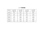
- FIG. 11 shows the data structure of the layer boundary 40 held by the layer boundary information management unit 204 of the hierarchy control unit 104.
- the node, port, link, and flow information in each NWDB is not limited to that described above.
- the maximum bandwidth, the remaining bandwidth, and bandwidth information reserved for the flow may be added to each port, or cost information for route calculation may be added as metric information in addition to link delay.
- the network to be controlled is an optical layer network
- available resource information and empty resource information may be added to the port.
- the resource information is the wavelength in the WDM layer, the time slot in the TDM layer, the flow identification information in the header in the layer based on packet switching (the label in the shim header in MPLS, the VID (VLAN Identifier) in VLAN (Virtual Local Area Network)) , OpenFlow supports matching tuple combinations, etc.).
- the user request unit 20 refers to the topology information of the NWDB 101 for users illustrated in FIG. 8 and performs flow route calculation based on the request condition of the flow to be set.
- a flow request condition a flow between the port P301 of the node N11 and the port P304 of the node N13 (see FIG. 7) is requested with a minimum delay.
- the route candidates for the flow from the node N11 to the node N13 two routes are shown in FIG. That is, the route candidates include a first route (total delay 200 msec) via links L901 (delay 100 msec) and L902 (delay 100 msec), and a second route (total delay 300 msec) via link L903 (delay 300 msec).
- the user request unit 20 selects the first route (L901-L902).
- the algorithm for calculating the path with the minimum delay is not particularly limited. For example, a Dijkstra algorithm in which the delay is regarded as the cost of the link can be considered.
- the user request unit 20 registers the flow F701 having the selected first route (L901-L902) in the NWDB 101 for users (step S401).
- a flow F701 in the NWDB 101 for users is schematically shown in FIG. At this time, the status of the flow information 101D in the user NWDB 101 shown in FIG.
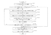
- the hierarchical control unit 104 checks whether or not a latent link is included in the route of the flow F701 (step S402).
- the flow F701 includes two latent links L901 and L902.
- the hierarchical control unit 104 first registers a flow corresponding to one latent link (in this case, the latent link L901) in the lower layer NWDB 103 (step S403).
- the lower layer path corresponding to the latent link L901 is a path that passes through the link L601 between the nodes N21 and N22.
- the port P402 of the node N21 and the port P403 of the node N22 included in the layer boundary 40 are selected as the end points of the flow. Accordingly, as shown in FIG.
- the hierarchy control unit 104 registers a flow F703 with the link L601 as a route and the ports P402 and P403 as endpoints in the lower layer NWDB 103. However, at this time, the status of the flow F703 is set to “setting”.
- the lower layer control unit 106 When the flow F703 is registered in the lower layer NWDB 103, the lower layer control unit 106 actually sets a flow in each network device of the lower layer network 31 according to the registered information of the flow F703 (step S404). When the flow setting is completed, the lower layer control unit 106 changes the status of the flow F703 in the lower layer NWDB 103 to “set” as illustrated in FIG.
- the hierarchical control unit 104 changes the latent link in the user NWDB 101 corresponding to the set flow F703 to “set” (step S405). Specifically, as shown in FIG. 14, Established (set) of the latent link L901 is changed to “TRUE”. Further, the virtual ports P802 and P803 at the end points of the latent link L901 are also associated with the ports of the higher layer NWDB 102. The end point ports of the flow F703 of the lower layer NWDB 103 are the port P402 of the node N21 and the port P403 of the node N22. Therefore, by referring to the layer boundary information shown in FIG.
- the ports of the upper layer network 32 corresponding to these ports are ports P306 and P307, respectively.
- the DB information correspondence management unit 205 associates the port P306 of the node N11 of the higher layer NWDB 102 with the virtual port P802 of the user-oriented NWDB 101.
- the inter-DB information correspondence management unit 205 further associates the port P307 of the node N12 of the higher layer NWDB 102 with the virtual port P803 of the user-oriented NWDB 101, and holds the correspondence between these ports.
- the virtual network information management unit 203 of the hierarchy control unit 104 changes the assigned values of the virtual ports P802 and P803 in the port information 101B of the user NWDB 101 to “TRUE”, respectively.
- the hierarchy control unit 104 registers the link of the user-facing NWDB 101 that has been changed to the setting in step S405 as a link in the higher layer NWDB 102 (step S406). More specifically, a link L001 corresponding to the link L901 of the user-facing NWDB 101 is registered between the ports P306 and P307 of the higher layer NWDB 102 based on the correspondence between the DB information held previously. At this time, other link information such as delay is also copied.
- the DB information correspondence management unit 205 also holds the correspondence relationship between the link L901 of the user-oriented NWDB 101 and the link L001 of the upper layer NWDB 102 as the correspondence between DB information.
- the hierarchical control unit 104 recalculates the latent links (step S407). Specifically, among the nodes of the upper layer network 32, the nodes in which links are set for all the ports at the layer boundary by the link flow setting up to this point are excluded from the virtual port creation target nodes of the NWDB 101 for users. Thus, the virtual port and the latent link of the excluded node are also deleted from the user-oriented NWDB 101. On the contrary, if there is a node having no virtual port in the user NWDB 101 even though there is a port at the layer boundary where no link is set in the upper layer, a virtual port and a potential link are added.
- the latent link is created with a full mesh
- the virtual port is added to all the virtual port creation target nodes including the node, and the latent link is created by the same operation as step S303 in FIG. If there is no latent link through which the flow registered in the user-oriented NWDB 101 passes due to this latent link rearrangement, the flow setting information is changed, so the status information of the flow is changed to setting failure.
- the user request unit 20 uses the topology information of the NWDB 101 for users to reset the flow to another route.
- the hierarchical control unit 104 performs the above steps S403 to S407 for all the latent links through which the flow initially registered in the user NWDB 101 passes (step S408). As described above, the processing for the potential link L901 out of the two potential links L901 and L902 included in the flow F701 is completed, but the other potential link L902 remains (No in step S408). Therefore, the above steps S403 to S407 are executed for the latent link L902.
- the hierarchy control unit 104 displays the NWDB 101 for the user.
- the information of the flow registered in step S409 is copied to the upper layer NWDB 102 (step S409).
- the information of the flow F701 in the NWDB 101 for the user is copied and registered as the flow F702 in the flow information 102D of the upper layer NWDB102, but the status of the flow F702 shown in FIG.
- the upper layer control unit 105 When a flow is registered in the upper layer NWDB 102, the upper layer control unit 105 actually sets a flow in each network device of the upper layer network 32 according to the registered information of the flow F702 (step S410). When the setting is completed, the upper layer control unit 105 changes the status information of the flow F702 of the upper layer NWDB 102 to “set” as illustrated in FIG. Upon detecting this change, the hierarchy control unit 104 changes the status of the flow F701 in the user NWDB 101 to “set”, as shown in FIG. The user request unit 20 can know the completion of the flow setting by changing the flow information of the NWDB 101 for users.
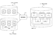
- the hierarchical control unit 104 sets a flow necessary for the lower layer network 31 and the upper layer network 32 as shown in FIG.
- the data structures of the user-oriented NWDB 101, the upper layer NWDB 102, and the lower layer NWDB 103 shown in FIG. 13 are illustrated in FIGS. 14, 15, and 16, respectively.
- flow information 101D is added in addition to the topology information (101A, 101B, 101C).
- the established information of the set link is “TRUE”, and the assigned information of the port associated with the port of the higher layer network is “TRUE”.
- flow information 103D is added.
- flow path information is held in the form of a list of links through which it passes.
- information on the node and port at the input end point of the flow is held in Match, and information on the node and port at the output end point of the flow is held in Action.
- a latent link is created in the NWDB 101 for users, and expected information such as a delay when a flow is set in a lower layer is entered.
- expected information such as a delay when a flow is set in a lower layer
- the user determines the route that matches the request of the flow to be set in consideration of link addition and sets the path.
- path setting can be performed in consideration of link addition for a section without a link in the lower layer network 31.
- the network control device according to the second embodiment of the present invention has the same configuration as the network control device according to the first embodiment. Below, the difference regarding the operation
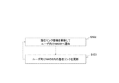
- the network control apparatus performs the operation shown in FIG. 17 in addition to the operation described in the first embodiment.
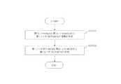
- the virtual network information management unit 203 periodically updates the latent link information (step S502).
- the processing performed in step S502 is equivalent to step S302 in the first embodiment.
- the virtual network information management unit 203 notifies the user-facing NWDB 101 of the latest latent link information (step S503).
- the process performed in step S503 is equivalent to step S303 in the first embodiment.
- the time interval before and after performing these steps repeatedly is determined by the path calculation scheduler 301. This time may be determined fixedly or dynamically based on a program or a set / designated value in advance, or may be determined in consideration of the load status of the network control device 10. Further, time, time, or information used for deriving these may be given as parameters of the latent link request created in step S302, and determination may be made based on the information.
- the latent link information recorded in the NWDB 101 for users can be continuously updated. Thereby, the effect by 1st Embodiment can be maintained.
- the network control device according to the third embodiment of the present invention has the same configuration as the network control device according to the first and second embodiments. Regarding the operation, only the difference between the present embodiment and the first and second embodiments will be described.
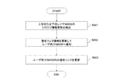
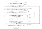
- the virtual network information management unit 203 detects that a change has occurred in the network state of one of the upper and lower layer networks 32 and 31 via the upper layer NWDB 102 or the lower layer NWDB 103 (step S601). This is performed by callback or message notification from the upper layer NWDB 102 or the lower layer NWDB 103 to the external DB access unit 202. Alternatively, it is performed by polling the upper layer NWDB 102 or the lower layer NWDB 103 by the external DB access unit 202.
- step S602 the virtual network information management unit 203 updates the latent link information and notifies the user-facing NWDB 101 of the latest latent link information.
- the processing performed in step S602 is equivalent to step S502 in the second embodiment.
- step S603 the latent link in the user NWDB 101 is updated with the one notified from the virtual network information management unit 203.
- the processing performed in step S603 is equivalent to step S503 in the second embodiment.
- the latent link information recorded in the user NWDB 101 can be immediately updated in response to a change in the state of the upper layer network 32 or the lower layer network 31 due to a reason not related to the network control apparatus 10. .
- the connection possibility of the latent link currently recorded on NWDB101 for users can be maintained.
- reasons that do not depend on the network control device 10 include failures, control and setting changes from another system, facility construction, and the like.
- the network control device according to the fourth embodiment of the present invention has the same configuration as the network control device according to the first to third embodiments. Regarding the operation, a difference between the present embodiment and the first to third embodiments will be described.
- the user can update the latent link request in the user-oriented NWDB 101 at any timing via the user request unit 20. Accordingly, the latent link request information in the user NWDB 101 is updated.
- the virtual network information management unit 203 detects this update by the same operation as in step S302 in the first embodiment. Then, the virtual network information management unit 203 updates the latent link information by the same operation as step S502 of the second embodiment, and notifies the user-facing NWDB 101 of the latest latent link information.
- the user-oriented NWDB 101 is updated with the latest latent link information notified by the same operation as in step S503 of the second embodiment.
- the user When a user adds a latent link request, the user adds a latent link request to the NWDB 101 for users via the user request unit 20 at an arbitrary timing.
- the operation after adding the latent link request is in accordance with the operation of the first embodiment.
- the user When the user deletes the latent link request, the user deletes the latent link request from the user-oriented NWDB 101 through the user request unit 20 at an arbitrary timing.
- the operation after deleting the latent link request conforms to the operation after step S602 in the third embodiment.
- the NWDB 101 for users may manage the latent link request in the soft state. That is, the NWDB 101 for users holds a timer for each latent link request, and deletes the latent link information when the predetermined time has elapsed. If there is an update to the same latent link request or the same request from the user before the predetermined time elapses, the timer is reset.
- the user can always notify the network control apparatus 10 of the change in the request for the latent link via the user-oriented NWDB 101. Thereby, the user can always receive the supply of the latent link he desires.
- the network control apparatus controls a three-layer network. In order from the lower layer, the first layer, the second layer, and the third layer are used.
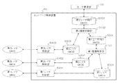
- the network control device 50 controls the first to third layer networks 33 to 35 according to the flow request from the user request unit 20 by the user.
- the network control device 50 includes first and second hierarchical control units 5101 and 5102, first and second user NWDBs 5201 and 5202, first to third layer NWDBs 5301 to 5303, and first to third layer control units. 5401-5403.
- the NWDB 5201 for the first user is the NWDB for the user of the first hierarchy control unit 5101 and the lower layer NWDB of the second hierarchy control unit 5102.
- the NWDB 5202 for the second user is an NWDB for the user of the second hierarchy control unit 5102.
- the first layer NWDB 5301 is a lower layer NWDB of the first hierarchy control unit 5101 and holds the network information of the first layer network 33.
- the second layer NWDB 5302 is an upper layer NWDB of the first hierarchy control unit 5101 and holds network information of the second layer network 34.
- the third layer NWDB 5303 is an upper layer NWDB of the second hierarchy control unit 5102 and holds network information of the third layer network 35.
- the first to third layer controllers 5401 to 5403 control the first to third layer networks 33 to 35 according to the respective information changes in the first to third layers NWDBs 5301 to 5303.
- the first to third layer control units 5401 to 5403 of the network control device 50 acquire the respective network information from the first to third layer networks 33 to 35.
- the first to third layer controllers 5401 to 5403 register node, port, and link information in the first to third layer NWDBs 5301 to 5303, respectively.
- the layer boundary information between the first layer and the second layer and the layer boundary information between the second layer and the third layer are set in the first layer control unit 5101 and the second layer control unit 5102, respectively.
- the first hierarchy control unit 5101 creates information on the NWDB 5201 for the first user with the first layer NWDB 5301 as the lower layer NWDB and the second layer NWDB 5302 as the upper layer NWDB (step S5501).
- the specific generation operation is the same as that of the first embodiment shown in FIG.
- the second tier control unit 5102 creates information on the NWDB 5202 for the second user with the NWDB 5201 for the first user as the lower layer NWDB and the third layer NWDB 5303 as the upper layer NWDB (step S5502).
- the specific generation operation is the same as that of the first embodiment shown in FIG. With the above operation, the information creation of the NWDBs 5201 and 5202 for the first and second users is completed.
- the user request unit 20 refers to the topology information of the second user NWDB 5202, performs flow path calculation based on the request condition of the flow to be set, and registers the flow in the second user NWDB 5202 (step S5601). ).
- the specific operation is the same as step S401 in FIG.
- the second hierarchy control unit 5102 checks whether or not a latent link is included in the registered flow path (step S5602).
- the second layer control unit 5102 registers the flow corresponding to the latent link in the NWDB 5201 for the first user corresponding to the lower layer NWDB as viewed from itself (step S5603).
- the specific operation is the same as step S402 in FIG.
- the first hierarchical control unit 5101 checks whether or not a latent link is included in the registered flow path (step S5604). If a latent link is included (Yes in step S5604), flow registration to the first layer NWDB 5301 by the first hierarchy control unit 5101 and flow setting by the first layer control unit 5401 are executed. Further, the link information change of the NWDB 5201 for the first user and the link information change of the second layer NWDB 5302 are executed by the first hierarchy control unit 5101 (step S5605). The specific operation is the same as that of the first embodiment, and is the operation from step S403 to S408 (Yes) in FIG.
- step S5605 After completion of step S5605 or when a latent link is not included (No in step S5604), the flow information copied to the second layer NWDB 5302 by the first hierarchy control unit 5101 for the flow registered in the NWDB 5201 for the first user Is done. Furthermore, the flow setting to the second layer network 34 is performed by the second layer control unit 5402 (step S5606).
- the specific operation is the same as in the first embodiment, and is steps S409 to S410 in FIG.
- step S5606 the flow setting of the NWDB 5201 for the first user, which is the lower layer NWDB of the second hierarchical control unit 5102, is completed.
- the second hierarchy control unit 5102 changes the latent link of the second user NWDB 5202 to the set link and registers the link information of the third layer NWDB 5303 (step S5607).
- the specific operation is similar to the operation of the first embodiment, and corresponds to steps S405 to S407 in FIG.
- step S5607 After the completion of step S5607, or when a latent link is not included in the registered flow route (No in step S5602), second layer control section 5102 transfers the flow registered in step S5601 to third layer NWDB 5303. sign up. Further, the third layer control unit 5403 sets a flow to the third layer network 35 (step S5608).
- the network control device 50 when a flow is added to the NWDB 5202 for the second user, the network control device 50 performs necessary settings for the networks 33 to 35 of the first layer, the second layer, and the third layer, respectively.
- a network control apparatus includes [(number of layers) ⁇ 1] hierarchical control units, so that a multi-layer network of three or more layers is included.
- the layer network can be controlled.
- a predetermined field of a PCEP (Path Computation Element communication Protocol) message is used as a message including a latent link request or a message notifying a generated latent link (for example, from a lower layer to an upper layer).
- a predetermined value can be used.
- the number of upper layer networks and lower layer networks, or the case where both the first to third layer networks are one, have been described for the sake of simplicity. However, there may be a plurality of networks in at least one of these layers.
- storage means for holding a policy regarding disclosure of latent links for each upper layer may be provided.
- the input of path calculation and / or the latent link information notified to each higher layer is changed according to the policy.
- flexible control according to the policy can be performed for each of a plurality of upper layers.
- the present invention can be applied to a service in which a carrier quickly provides a virtual network on demand to a user.
- the present invention can be applied to a VPN (Virtual Private Network) service that connects user base networks, a network control portion of a data center and a user base, or a cloud service that connects data centers to each other.
- VPN Virtual Private Network
- [Appendix 1] As in the network control device according to the first aspect.
- [Appendix 2] The performance includes at least one of bandwidth, delay, reliability, and priority of the link.
- [Appendix 3] The hierarchical control unit obtains the link and the performance based on topology information of a layer boundary between the upper layer network and the lower layer network, and topology information of the lower layer network.
- [Appendix 4] The hierarchical control unit obtains the flow path based on the topology information of the upper layer network and the link; The network control device according to any one of appendices 1 to 3.
- the hierarchy control unit periodically performs an operation of obtaining and associating the link and the performance, The network control device according to any one of appendices 1 to 4.
- the hierarchical control unit performs an operation of obtaining and associating the link and the performance when the state of at least one of the upper layer network and the lower layer network changes, The network control device according to any one of appendices 1 to 5.
- [Appendix 7] Applying the network control operation by the network control device according to any one of appendices 1 to 6 to at least one of a set of two networks that are vertically adjacent to each other among a plurality of networks of three or more layers; A network control device.
- the network control method according to the second aspect is as described above.
- the performance includes at least one of bandwidth, delay, reliability, and priority of the link.
- the network control device obtains the link and the performance based on topology information of a layer boundary between the upper layer network and the lower layer network and topology information of the lower layer network.
- the network control device includes a step of obtaining a path of the flow based on topology information of the upper layer network and the link; The network control method according to any one of appendices 8 to 10.
- the network control apparatus periodically performs an operation of obtaining and associating the link and the performance, The network control method according to any one of appendices 8 to 11.
- the network control device performs an operation of obtaining and maintaining the link and the performance in association with each other when a state of at least one of the upper layer network and the lower layer network changes.
- the network control apparatus applies the network control method according to any one of appendices 8 to 13 to at least one of a set of two adjacent networks above and below a plurality of networks of three or more layers. To A network control method.
- the program according to the third aspect is as described above.
- the performance includes at least one of bandwidth, delay, reliability, and priority of the link.
- [Appendix 17] Causing the computer to execute processing for obtaining the link and the performance based on topology information of a layer boundary between the upper layer network and the lower layer network, and topology information of the lower layer network;
- [Appendix 18] Causing the computer to execute processing for obtaining a route of the flow based on the topology information of the upper layer network and the link;
- [Appendix 19] Causing the computer to execute a process of periodically performing an operation of obtaining and associating and maintaining the link and the performance; The program according to any one of appendices 15 to 18.
- [Appendix 20] Causing the computer to execute a process to be performed when the state of at least one of the upper layer network and the lower layer network is changed, and the operation of obtaining and maintaining the link and the performance in association with each other; The program according to any one of appendices 15 to 19.
- Appendix 21 A process of applying the network control operation by the program according to any one of appendices 15 to 20 to at least one of a set of two networks adjacent to each other above and below a plurality of networks of three or more layers; Causing the computer to execute, A program characterized by that.
Landscapes
- Engineering & Computer Science (AREA)
- Computer Networks & Wireless Communication (AREA)
- Signal Processing (AREA)
- Data Exchanges In Wide-Area Networks (AREA)
Abstract
Priority Applications (2)
| Application Number | Priority Date | Filing Date | Title |
|---|---|---|---|
| US15/555,324 US10313232B2 (en) | 2015-03-06 | 2016-03-03 | Network control device, network control method, and recording medium for program |
| JP2017504859A JP6733655B2 (ja) | 2015-03-06 | 2016-03-03 | ネットワーク制御装置、ネットワーク制御方法、および、プログラム |
Applications Claiming Priority (2)
| Application Number | Priority Date | Filing Date | Title |
|---|---|---|---|
| JP2015-044737 | 2015-03-06 | ||
| JP2015044737 | 2015-03-06 |
Publications (1)
| Publication Number | Publication Date |
|---|---|
| WO2016143310A1 true WO2016143310A1 (fr) | 2016-09-15 |
Family
ID=56879461
Family Applications (1)
| Application Number | Title | Priority Date | Filing Date |
|---|---|---|---|
| PCT/JP2016/001150 Ceased WO2016143310A1 (fr) | 2015-03-06 | 2016-03-03 | Dispositif de commande de réseau, procédé de commande de réseau et support d'enregistrement pour programme |
Country Status (3)
| Country | Link |
|---|---|
| US (1) | US10313232B2 (fr) |
| JP (1) | JP6733655B2 (fr) |
| WO (1) | WO2016143310A1 (fr) |
Cited By (1)
| Publication number | Priority date | Publication date | Assignee | Title |
|---|---|---|---|---|
| WO2022176043A1 (fr) * | 2021-02-17 | 2022-08-25 | 日本電信電話株式会社 | Dispositif et procédé de commande de sélection de trajet, et programme |
Families Citing this family (3)
| Publication number | Priority date | Publication date | Assignee | Title |
|---|---|---|---|---|
| JP6863305B2 (ja) * | 2018-01-29 | 2021-04-21 | オムロン株式会社 | ネットワークシステム、制御方法および制御装置 |
| JP7206920B2 (ja) * | 2019-01-08 | 2023-01-18 | 富士フイルムビジネスイノベーション株式会社 | 情報処理装置及びプログラム |
| CN113300928B (zh) * | 2020-02-21 | 2023-01-13 | 华为技术有限公司 | 一种传输业务报文的方法、设备和系统 |
Citations (1)
| Publication number | Priority date | Publication date | Assignee | Title |
|---|---|---|---|---|
| WO2014054691A1 (fr) * | 2012-10-03 | 2014-04-10 | 日本電気株式会社 | Programme, procédé de commande, appareil de commande et système de communication |
Family Cites Families (10)
| Publication number | Priority date | Publication date | Assignee | Title |
|---|---|---|---|---|
| US6400681B1 (en) | 1996-06-20 | 2002-06-04 | Cisco Technology, Inc. | Method and system for minimizing the connection set up time in high speed packet switching networks |
| US7889675B2 (en) | 2003-01-31 | 2011-02-15 | Tellabs Operations, Inc. | Method and system for multi-layer network routing |
| GB0407336D0 (en) | 2004-03-31 | 2004-05-05 | British Telecomm | Pathfinding system |
| JP4283736B2 (ja) | 2004-06-25 | 2009-06-24 | 日本電信電話株式会社 | トラヒック情報処理方法、トラヒック情報処理プログラム、および、トラヒック情報処理装置 |
| DE102005048585A1 (de) * | 2005-10-06 | 2007-04-12 | Robert Bosch Gmbh | Teilnehmer und Kommunikationscontroller eines Kommunikationssystems und Verfahren zur Realisierung einer Gateway-Funktionalität in einem Teilnehmer eines Kommunikationssystems |
| JP4621220B2 (ja) | 2007-02-27 | 2011-01-26 | 日本電信電話株式会社 | 仮想トポロジ設計装置および仮想トポロジ設計方法 |
| US20100287273A1 (en) * | 2009-05-05 | 2010-11-11 | Motorola, Inc. | System and method for directing communications within a heterogeneous network environment |
| US8098584B2 (en) * | 2009-08-07 | 2012-01-17 | Microsoft Corporation | Optimization of traffic routing for data center services |
| CN102130824B (zh) * | 2010-10-30 | 2014-09-17 | 华为技术有限公司 | 网络联合优化方法和装置 |
| US8976711B2 (en) * | 2011-10-07 | 2015-03-10 | Futurewei Technologies, Inc. | Simple topology transparent zoning in network communications |
-
2016
- 2016-03-03 WO PCT/JP2016/001150 patent/WO2016143310A1/fr not_active Ceased
- 2016-03-03 US US15/555,324 patent/US10313232B2/en active Active
- 2016-03-03 JP JP2017504859A patent/JP6733655B2/ja active Active
Patent Citations (1)
| Publication number | Priority date | Publication date | Assignee | Title |
|---|---|---|---|---|
| WO2014054691A1 (fr) * | 2012-10-03 | 2014-04-10 | 日本電気株式会社 | Programme, procédé de commande, appareil de commande et système de communication |
Non-Patent Citations (2)
| Title |
|---|
| YOHEI IIZAWA ET AL.: "Dynamic Multi-layer Path Control Using Virtual Links", PROCEEDINGS OF THE 2014 IEICE GENERAL CONFERENCE TSUSHIN 2, 21 March 2014 (2014-03-21), pages 162 * |
| YOHEI IIZAWA ET AL.: "ICT System o Kodoka suru SDN Tokushu Heterogeneous-mo Togo Seigyo Kiban o Jitsugen suru Multilayer Chushoka Gijutsu", NEC TECHNICAL JOURNAL, vol. 66, no. 2, 1 February 2014 (2014-02-01), pages 44 - 47 * |
Cited By (1)
| Publication number | Priority date | Publication date | Assignee | Title |
|---|---|---|---|---|
| WO2022176043A1 (fr) * | 2021-02-17 | 2022-08-25 | 日本電信電話株式会社 | Dispositif et procédé de commande de sélection de trajet, et programme |
Also Published As
| Publication number | Publication date |
|---|---|
| US20180062982A1 (en) | 2018-03-01 |
| JP6733655B2 (ja) | 2020-08-05 |
| JPWO2016143310A1 (ja) | 2017-12-21 |
| US10313232B2 (en) | 2019-06-04 |
Similar Documents
| Publication | Publication Date | Title |
|---|---|---|
| JP6699654B2 (ja) | ネットワーク制御装置、ネットワーク制御方法、および、プログラム | |
| ES2665571T3 (es) | Control de servicio en nube informática y arquitectura de gestión extendida para conectarse al estrato de red | |
| JP5919046B2 (ja) | パス計算方法 | |
| US9071532B2 (en) | Method for discovery and load balancing of path computation elements based on transport plane link metrics | |
| US10511524B2 (en) | Controller communications in access networks | |
| US11418428B2 (en) | Recomputation of multipaths in a segment routing-enabled network | |
| JP6733655B2 (ja) | ネットワーク制御装置、ネットワーク制御方法、および、プログラム | |
| WO2013041028A1 (fr) | Système et procédé pour calculer un chemin à contraintes le plus court inter-domaine dans un réseau informatique | |
| WO2015059917A1 (fr) | Procédé et dispositif de commande de réseau multicouches | |
| US9819573B2 (en) | Method for scalable computer network partitioning | |
| WO2021004213A1 (fr) | Procédé et appareil pour déterminer une étiquette de chemin de réseau de fusion, support de stockage et dispositif électronique | |
| EP3136649A1 (fr) | Procédé et système pour fournir des informations de charge d'un système de transmission optique de données | |
| JP5668579B2 (ja) | 通信装置及び経路決定方法 | |
| EP2852178B1 (fr) | Procédé et appareil de mise à l'échelle de routage d'ingénierie de trafic dans un réseau | |
| JP6384481B2 (ja) | ネットワーク設計支援装置、ネットワーク設計方法及びプログラム | |
| US9544225B2 (en) | Method for end point identification in computer networks | |
| EP4075751B1 (fr) | Mise à l'échelle horizontale d'un contrôleur de réseau pour la gestion des sessions de configuration d'un dispositif réseau | |
| US20200084158A1 (en) | Methods and apparatus for path computation in a telecommunications network | |
| JP5076991B2 (ja) | 経路計算システム | |
| JPWO2017169947A1 (ja) | 運用装置、通信システムおよび更新方法 | |
| WO2015080092A1 (fr) | Dispositif de commande de réseau, système de réseau, procédé de commande de réseau et programme | |
| EP3588874A1 (fr) | Procédé et appareil de réglage de bande passante en fonction des exigences, et support de stockage informatique | |
| CN105791115A (zh) | 一种流路径计算方法及装置 |
Legal Events
| Date | Code | Title | Description |
|---|---|---|---|
| 121 | Ep: the epo has been informed by wipo that ep was designated in this application |
Ref document number: 16761285 Country of ref document: EP Kind code of ref document: A1 |
|
| ENP | Entry into the national phase |
Ref document number: 2017504859 Country of ref document: JP Kind code of ref document: A |
|
| WWE | Wipo information: entry into national phase |
Ref document number: 15555324 Country of ref document: US |
|
| NENP | Non-entry into the national phase |
Ref country code: DE |
|
| 122 | Ep: pct application non-entry in european phase |
Ref document number: 16761285 Country of ref document: EP Kind code of ref document: A1 |