US10877146B2 - Radar sensor, radar sensor system, and method for determining the position of an object using horizontal and vertical digital beam formation for measuring point-reflective and surface-reflective objects - Google Patents
Radar sensor, radar sensor system, and method for determining the position of an object using horizontal and vertical digital beam formation for measuring point-reflective and surface-reflective objects Download PDFInfo
- Publication number
- US10877146B2 US10877146B2 US15/532,400 US201515532400A US10877146B2 US 10877146 B2 US10877146 B2 US 10877146B2 US 201515532400 A US201515532400 A US 201515532400A US 10877146 B2 US10877146 B2 US 10877146B2
- Authority
- US
- United States
- Prior art keywords
- radar sensor
- antenna
- sensor system
- vertical
- horizontal
- Prior art date
- Legal status (The legal status is an assumption and is not a legal conclusion. Google has not performed a legal analysis and makes no representation as to the accuracy of the status listed.)
- Active, expires
Links
- 230000015572 biosynthetic process Effects 0.000 title claims description 16
- 238000000034 method Methods 0.000 title claims description 16
- 238000012544 monitoring process Methods 0.000 claims description 5
- 238000001514 detection method Methods 0.000 description 13
- 238000010586 diagram Methods 0.000 description 13
- 238000012545 processing Methods 0.000 description 3
- 238000011156 evaluation Methods 0.000 description 2
- 238000003384 imaging method Methods 0.000 description 2
- 239000011159 matrix material Substances 0.000 description 2
- 230000004888 barrier function Effects 0.000 description 1
- 238000004891 communication Methods 0.000 description 1
- 238000010276 construction Methods 0.000 description 1
- 230000001276 controlling effect Effects 0.000 description 1
- 238000005259 measurement Methods 0.000 description 1
- 230000001105 regulatory effect Effects 0.000 description 1
- 230000035945 sensitivity Effects 0.000 description 1
- 230000001360 synchronised effect Effects 0.000 description 1
- 238000012360 testing method Methods 0.000 description 1
- 238000011144 upstream manufacturing Methods 0.000 description 1
Images




Classifications
-
- G—PHYSICS
- G01—MEASURING; TESTING
- G01S—RADIO DIRECTION-FINDING; RADIO NAVIGATION; DETERMINING DISTANCE OR VELOCITY BY USE OF RADIO WAVES; LOCATING OR PRESENCE-DETECTING BY USE OF THE REFLECTION OR RERADIATION OF RADIO WAVES; ANALOGOUS ARRANGEMENTS USING OTHER WAVES
- G01S7/00—Details of systems according to groups G01S13/00, G01S15/00, G01S17/00
- G01S7/02—Details of systems according to groups G01S13/00, G01S15/00, G01S17/00 of systems according to group G01S13/00
- G01S7/03—Details of HF subsystems specially adapted therefor, e.g. common to transmitter and receiver
-
- G—PHYSICS
- G01—MEASURING; TESTING
- G01S—RADIO DIRECTION-FINDING; RADIO NAVIGATION; DETERMINING DISTANCE OR VELOCITY BY USE OF RADIO WAVES; LOCATING OR PRESENCE-DETECTING BY USE OF THE REFLECTION OR RERADIATION OF RADIO WAVES; ANALOGOUS ARRANGEMENTS USING OTHER WAVES
- G01S13/00—Systems using the reflection or reradiation of radio waves, e.g. radar systems; Analogous systems using reflection or reradiation of waves whose nature or wavelength is irrelevant or unspecified
- G01S13/02—Systems using reflection of radio waves, e.g. primary radar systems; Analogous systems
- G01S13/06—Systems determining position data of a target
- G01S13/42—Simultaneous measurement of distance and other co-ordinates
-
- G—PHYSICS
- G01—MEASURING; TESTING
- G01S—RADIO DIRECTION-FINDING; RADIO NAVIGATION; DETERMINING DISTANCE OR VELOCITY BY USE OF RADIO WAVES; LOCATING OR PRESENCE-DETECTING BY USE OF THE REFLECTION OR RERADIATION OF RADIO WAVES; ANALOGOUS ARRANGEMENTS USING OTHER WAVES
- G01S13/00—Systems using the reflection or reradiation of radio waves, e.g. radar systems; Analogous systems using reflection or reradiation of waves whose nature or wavelength is irrelevant or unspecified
- G01S13/87—Combinations of radar systems, e.g. primary radar and secondary radar
-
- G—PHYSICS
- G01—MEASURING; TESTING
- G01S—RADIO DIRECTION-FINDING; RADIO NAVIGATION; DETERMINING DISTANCE OR VELOCITY BY USE OF RADIO WAVES; LOCATING OR PRESENCE-DETECTING BY USE OF THE REFLECTION OR RERADIATION OF RADIO WAVES; ANALOGOUS ARRANGEMENTS USING OTHER WAVES
- G01S13/00—Systems using the reflection or reradiation of radio waves, e.g. radar systems; Analogous systems using reflection or reradiation of waves whose nature or wavelength is irrelevant or unspecified
- G01S13/88—Radar or analogous systems specially adapted for specific applications
- G01S13/93—Radar or analogous systems specially adapted for specific applications for anti-collision purposes
- G01S13/931—Radar or analogous systems specially adapted for specific applications for anti-collision purposes of land vehicles
-
- G—PHYSICS
- G01—MEASURING; TESTING
- G01S—RADIO DIRECTION-FINDING; RADIO NAVIGATION; DETERMINING DISTANCE OR VELOCITY BY USE OF RADIO WAVES; LOCATING OR PRESENCE-DETECTING BY USE OF THE REFLECTION OR RERADIATION OF RADIO WAVES; ANALOGOUS ARRANGEMENTS USING OTHER WAVES
- G01S7/00—Details of systems according to groups G01S13/00, G01S15/00, G01S17/00
- G01S7/02—Details of systems according to groups G01S13/00, G01S15/00, G01S17/00 of systems according to group G01S13/00
- G01S7/41—Details of systems according to groups G01S13/00, G01S15/00, G01S17/00 of systems according to group G01S13/00 using analysis of echo signal for target characterisation; Target signature; Target cross-section
-
- H—ELECTRICITY
- H01—ELECTRIC ELEMENTS
- H01Q—ANTENNAS, i.e. RADIO AERIALS
- H01Q1/00—Details of, or arrangements associated with, antennas
- H01Q1/27—Adaptation for use in or on movable bodies
- H01Q1/32—Adaptation for use in or on road or rail vehicles
- H01Q1/3208—Adaptation for use in or on road or rail vehicles characterised by the application wherein the antenna is used
- H01Q1/3233—Adaptation for use in or on road or rail vehicles characterised by the application wherein the antenna is used particular used as part of a sensor or in a security system, e.g. for automotive radar, navigation systems
-
- H—ELECTRICITY
- H01—ELECTRIC ELEMENTS
- H01Q—ANTENNAS, i.e. RADIO AERIALS
- H01Q21/00—Antenna arrays or systems
- H01Q21/06—Arrays of individually energised antenna units similarly polarised and spaced apart
- H01Q21/061—Two dimensional planar arrays
-
- E—FIXED CONSTRUCTIONS
- E05—LOCKS; KEYS; WINDOW OR DOOR FITTINGS; SAFES
- E05F—DEVICES FOR MOVING WINGS INTO OPEN OR CLOSED POSITION; CHECKS FOR WINGS; WING FITTINGS NOT OTHERWISE PROVIDED FOR, CONCERNED WITH THE FUNCTIONING OF THE WING
- E05F15/00—Power-operated mechanisms for wings
- E05F15/40—Safety devices, e.g. detection of obstructions or end positions
- E05F15/42—Detection using safety edges
- E05F15/43—Detection using safety edges responsive to disruption of energy beams, e.g. light or sound
-
- E—FIXED CONSTRUCTIONS
- E05—LOCKS; KEYS; WINDOW OR DOOR FITTINGS; SAFES
- E05F—DEVICES FOR MOVING WINGS INTO OPEN OR CLOSED POSITION; CHECKS FOR WINGS; WING FITTINGS NOT OTHERWISE PROVIDED FOR, CONCERNED WITH THE FUNCTIONING OF THE WING
- E05F15/00—Power-operated mechanisms for wings
- E05F15/40—Safety devices, e.g. detection of obstructions or end positions
- E05F15/42—Detection using safety edges
- E05F15/43—Detection using safety edges responsive to disruption of energy beams, e.g. light or sound
- E05F2015/432—Detection using safety edges responsive to disruption of energy beams, e.g. light or sound with acoustical sensors
- E05F2015/433—Detection using safety edges responsive to disruption of energy beams, e.g. light or sound with acoustical sensors using reflection from the obstruction
-
- G—PHYSICS
- G01—MEASURING; TESTING
- G01S—RADIO DIRECTION-FINDING; RADIO NAVIGATION; DETERMINING DISTANCE OR VELOCITY BY USE OF RADIO WAVES; LOCATING OR PRESENCE-DETECTING BY USE OF THE REFLECTION OR RERADIATION OF RADIO WAVES; ANALOGOUS ARRANGEMENTS USING OTHER WAVES
- G01S13/00—Systems using the reflection or reradiation of radio waves, e.g. radar systems; Analogous systems using reflection or reradiation of waves whose nature or wavelength is irrelevant or unspecified
- G01S13/88—Radar or analogous systems specially adapted for specific applications
- G01S13/93—Radar or analogous systems specially adapted for specific applications for anti-collision purposes
- G01S13/931—Radar or analogous systems specially adapted for specific applications for anti-collision purposes of land vehicles
- G01S2013/9314—Parking operations
-
- G—PHYSICS
- G01—MEASURING; TESTING
- G01S—RADIO DIRECTION-FINDING; RADIO NAVIGATION; DETERMINING DISTANCE OR VELOCITY BY USE OF RADIO WAVES; LOCATING OR PRESENCE-DETECTING BY USE OF THE REFLECTION OR RERADIATION OF RADIO WAVES; ANALOGOUS ARRANGEMENTS USING OTHER WAVES
- G01S13/00—Systems using the reflection or reradiation of radio waves, e.g. radar systems; Analogous systems using reflection or reradiation of waves whose nature or wavelength is irrelevant or unspecified
- G01S13/88—Radar or analogous systems specially adapted for specific applications
- G01S13/93—Radar or analogous systems specially adapted for specific applications for anti-collision purposes
- G01S13/931—Radar or analogous systems specially adapted for specific applications for anti-collision purposes of land vehicles
- G01S2013/9327—Sensor installation details
- G01S2013/93274—Sensor installation details on the side of the vehicles
Definitions
- the invention relates to a radar sensor, a radar sensor system and to a method for determining the position of an object.
- Millimetre wave radar sensors e.g. for automotive and aeronautical applications, should exhibit a compact and inexpensive construction.
- Another application is so-called parking assistance with which, for example, a distinction must be made between potentially colliding objects and low curbstones.
- planar surfaces only exhibit significant reflection when the incident radar beam is vertical, whereas with punctiform reflectors this incident beam can also be at other angles. This fact may lead to the contour of extensive planar surfaces not being recognised, and a collision may occur, in particular, with automatically opening doors.
- the object of the invention is to make available an apparatus, a method and a radar system by means of which the disadvantages described above are avoided. Furthermore, it is the object of the invention to make available a radar sensor and a radar sensor system and an apparatus and a method by means of which a vertical position of an object can be determined and with the aid of which classification distinguishing between punctiform and flat objects can be performed.
- a corrective is provided which is arranged offset with respect to the first in the direction of travel.
- the sensors are linked to one another, and the information that is collected is evaluated by one of the two sensors by the master/slave principle.
- FIG. 1 shows the sensor arrangement on the vehicle with a horizontal field of vision for monitoring the opening range of the doors.
- the sensors are each fitted tilted by approx. 30 degrees and have a field of vision of approx. 110 degrees.
- At least 2 sensors are to be fitted on each side of the vehicle in order to cover the opening range of the doors optimally.
- FIG. 2 shows the vertical field of vision of the sensors and the range of potential obstacles.
- the arrangement of the sensors has been chosen so that on the one hand the opening range of the doors is covered maximally, and on the other hand so that punctiform reflectors can be distinguished from flat reflectors. Overlapping of the fields of vision of the sensors is required for this purpose.
- the door may open up to the object, whereas with flat obstacles, such as for example walls or vehicles parked adjacent, the door may only open to the potentially extended surface.
- FIG. 3 the detection of a punctiform reflector
- FIG. 4 the detection of a planar, flat object is sketched.
- the distance and the angle of the punctiform object is detected by both sensors.
- the radar sensors detect the radial distance and the angle in relation to the point of reflection. If one now forms the orthogonals to the beam directions of the individual sensors, the latter run approximately parallel with a surface target and cross with a point target. With the point target the doors may be opened up to its position, and with a surface target only up to the extended orthogonal. The doors are thus prevented from touching the wall when opened, even though the reflection point is further away than the collision point.
- FIG. 1 shows the sensor arrangement on the vehicle with a horizontal field of vision for monitoring the opening range of the doors.
- FIG. 2 shows the vertical field of vision of the sensors and the range of potential obstacles.
- FIG. 3 shows the detection of a punctiform reflector.
- FIG. 4 shows the detection of a planar, flat object.
- FIG. 5 shows the millimetre wave module of an individual radar sensor with an antenna arrangement.
- FIG. 6 shows the functional block diagram of the radar sensor.
- FIG. 7 shows the time diagram and the modulation form of an individual transmitting/receiving unit.
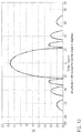
- FIG. 8 shows a vertical diagram of an antenna line.
- FIG. 9 shows a horizontal diagram of the antenna line.
- FIG. 10 shows an array
- FIG. 11 shows an opening angle of an emitter.
- FIG. 12 shows the millimetre wave module with two transmitting/receiving modules.
- FIG. 13 shows the controllable diagram of the array with a 3 dB beam width of 16 degrees in the horizontal and 29 degrees in the vertical.
- FIG. 5 shows the millimetre wave module of an individual radar sensor with an antenna arrangement.
- the sensor consists of a transmitting/receiving device ( 1 ) for the vertical scan and a transmitting/receiving device ( 2 ) for the horizontal scan. Every transmitting/receiving device consists of at least 4 receivers ( 3 a , 3 b ) and one or two transmitters ( 4 a , 4 b ). Since the required detection rate for the door monitoring is low in comparison to the measuring rate of the sensor, the sensor system can perform the vertical detection and the horizontal detection one after the other chronologically. This reduces costs because only one signal processing unit is required. Furthermore, the transmitting/receiving units are prevented from disrupting one another.
- FIG. 6 shows the functional block diagram of the radar sensor. It consists of two highly integrated radar front ends, each with two transmitters and four receivers. Analogue to digital converters are already integrated into the receivers so that the latter can be connected directly to the signal processing unit—a multicore digital signal processor.
- the signal processor additionally performs the task of controlling the transmitting/receiving modules and operates the communication interface with the outside world, e.g. with the control electronics of the automatic door.
- the vertical and the horizontal angular position of the object to be detected is now determined and the distance from the object is measured.
- the individual transmitters of a pair of transmitters are operated one after the other chronologically here.
- the bringing together of the information from the two detection processes corresponds to the detection with just one transmitter and reception with a virtual array ( 3 a ′, 3 b ′) which is twice as great as the real array.
- the angle measuring accuracy can thus be increased by a factor of 2. If this is not required, the detection can also be operated with just one transmitter.
- FIG. 7 shows the time diagram and the modulation form of an individual transmitting/receiving unit.
- the frequency of the two transmitters is modulated alternately, linearly and in the form of saw teeth. This cycle is repeated n times.
- the distance from the object is determined from the sets of data of the individual modulation ramps with the aid of a Fast Fourier Transform (FFT). Afterwards these sets of data are arranged to form a spectrogram and a second FFT is calculated by means of the columns of the spectrogram matrix.
- the line position of this so-called range-Doppler matrix corresponds to the speed of the object, and the column position corresponds to the radial distance.
- the modulation frequency fm is greater than the maximum Doppler frequency that occurs, and so an independent and clear distance and speed measurement can be taken.
- an antenna line has been chosen which has the vertical diagram shown in FIG. 8 .
- the arrangement and dimensioning of the individual emitter elements of the antenna line has not been optimised here to the maximum beam bundling as is otherwise normal, but is designed so that an upwardly directed fan-shaped beam is formed.
- This fan-shaped beam ensures that reflections of objects which are suppressed when they lie beneath the door sill and the sensor can also still detect objects with high vertical angles.
- the gain of this type of antenna line corresponds approximately to only that of an individual emitter. However, the distance from the objects is so small that the radar sensor is still sufficiently sensitive.
- FIG. 9 The horizontal diagram of this antenna line is illustrated in FIG. 9 . It has a very large 3 dB beam width in order to illuminate the required wide range of vision of 110°.
- the array diagram shown in FIG. 10 is produced which can be swivelled by up to +50° without so-called grating lobes being produced which could lead to dummy targets.
- microstrip patch emitter that is used.
- This emitter has a large opening angle in both the vertical and the horizontal (see FIG. 11 ).
- the digital beam scanning is restricted here to the angle range of ⁇ 70° to 0°.
- ⁇ 70° dummy targets occur in the opposite direction. However, these would lie physically beneath the surface of the road, and so can be eliminated by a simple plausibility test. Up to a swivel angle of ⁇ 60° the detection is free from grating lobes, and so from dummy targets.
- the door opening range is therefore monitored two-dimensionally by the alternately horizontal and vertical scan, and so protruding obstacles such as loading ramps, handrails or exterior mirrors of adjacent vehicles can also be recognised as obstacles.
- FIG. 12 shows the millimetre wave module with two transmitting/receiving modules which make available 4 transmitters and 8 receivers.
- the transmitting antennas are arranged in a row orthogonal to the row of receiving antennas.
- the transmitting antennas should have the same polarisation direction here as the receiving antenna in order to guarantee the maximum system sensitivity.
- the antennas are fed on the same level, as can be seen for example in FIG. 5 , with the necessary spacing of the transmitting/emitting elements a line run feeding the emitting elements would not be possible.
- the emitter elements have been tilted by 45° on the transmitter as well as on the receiver.
- the phase and the amplitude of each of these individual emitters can be regulated so that beam scanning is possible in the vertical as well as in the horizontal direction.
- FIG. 13 shows the controllable diagram of the array with a 3 dB beam width of 16 degrees in the horizontal and 29 degrees in the vertical.
Landscapes
- Engineering & Computer Science (AREA)
- Radar, Positioning & Navigation (AREA)
- Remote Sensing (AREA)
- Physics & Mathematics (AREA)
- Computer Networks & Wireless Communication (AREA)
- General Physics & Mathematics (AREA)
- Electromagnetism (AREA)
- Computer Security & Cryptography (AREA)
- Radar Systems Or Details Thereof (AREA)
- Variable-Direction Aerials And Aerial Arrays (AREA)
- Details Of Aerials (AREA)
- Support Of Aerials (AREA)
Applications Claiming Priority (4)
| Application Number | Priority Date | Filing Date | Title |
|---|---|---|---|
| DE102014118031.3 | 2014-12-05 | ||
| DE102014118031.3A DE102014118031A1 (de) | 2014-12-05 | 2014-12-05 | Radarsensor, Radarsensor-System sowie Verfahren zur Bestimmung der Position eines Objekts mit horizontaler und vertikaler digitaler Strahlformung zur Vermessung von punkt- und flächenförmig reflektierenden Objekten |
| DE102014118031 | 2014-12-05 | ||
| PCT/EP2015/078879 WO2016087679A1 (fr) | 2014-12-05 | 2015-12-07 | Capteur radar, système de capteur radar, ainsi que procédé permettant de déterminer la position d'un objet par formation numérique horizontale et verticale de faisceaux pour mesurer des objets réfléchis sous forme de points ou de surfaces |
Publications (2)
| Publication Number | Publication Date |
|---|---|
| US20170329002A1 US20170329002A1 (en) | 2017-11-16 |
| US10877146B2 true US10877146B2 (en) | 2020-12-29 |
Family
ID=55070986
Family Applications (1)
| Application Number | Title | Priority Date | Filing Date |
|---|---|---|---|
| US15/532,400 Active 2036-03-18 US10877146B2 (en) | 2014-12-05 | 2015-12-07 | Radar sensor, radar sensor system, and method for determining the position of an object using horizontal and vertical digital beam formation for measuring point-reflective and surface-reflective objects |
Country Status (7)
| Country | Link |
|---|---|
| US (1) | US10877146B2 (fr) |
| EP (1) | EP3227719A1 (fr) |
| JP (1) | JP6734847B2 (fr) |
| KR (1) | KR102550833B1 (fr) |
| CN (1) | CN107407720B (fr) |
| DE (1) | DE102014118031A1 (fr) |
| WO (1) | WO2016087679A1 (fr) |
Cited By (4)
| Publication number | Priority date | Publication date | Assignee | Title |
|---|---|---|---|---|
| US20220236370A1 (en) * | 2021-01-27 | 2022-07-28 | Aptiv Technologies Limited | Radar System with Paired One-Dimensional and Two-Dimensional Antenna Arrays |
| US20230105684A1 (en) * | 2021-10-01 | 2023-04-06 | Gm Cruise Holdings Llc | System and method for end of line test and calibration of angular scanning radar |
| FR3128030A1 (fr) | 2021-10-12 | 2023-04-14 | Psa Automobiles Sa | Dispositif de détection d’obstacles et procédé de calibration automatique d’un tel dispositif. |
| US11847833B2 (en) | 2020-02-12 | 2023-12-19 | Strattec Security Corporation | Broad coverage non-contact obstacle detection |
Families Citing this family (38)
| Publication number | Priority date | Publication date | Assignee | Title |
|---|---|---|---|---|
| WO2016153265A1 (fr) * | 2015-03-26 | 2016-09-29 | 엘지전자 주식회사 | Procédé et dispositif pour estimer une fréquence doppler par utilisation d'un processus de balayage de faisceau dans un système de communication sans fil |
| US10446938B1 (en) | 2015-12-23 | 2019-10-15 | Apple Inc. | Radar system including dual receive array |
| WO2017218876A1 (fr) * | 2016-06-17 | 2017-12-21 | Quovard Management Llc | Réseau d'antennes radar |
| DE102016213007A1 (de) * | 2016-07-15 | 2018-01-18 | Robert Bosch Gmbh | Verfahren und System zur Abtastung eines Objekts |
| KR102578824B1 (ko) * | 2016-11-30 | 2023-09-15 | 삼성전자주식회사 | 3차원 정보를 제공하는 차량용 레이더 장치 |
| DE102017200273A1 (de) * | 2017-01-10 | 2018-07-12 | Audi Ag | Radaranordnung für ein Kraftfahrzeug und Kraftfahrzeug |
| CN106950949B (zh) * | 2017-02-20 | 2021-04-13 | 江苏大学 | 一种车辆沿边导航的七光电开关弧形阵列与方法 |
| DE102017223471A1 (de) * | 2017-12-20 | 2019-06-27 | Robert Bosch Gmbh | Vorrichtung zum Aussenden und Empfangen elektromagnetischer Strahlung |
| KR102474591B1 (ko) | 2018-01-24 | 2022-12-05 | 삼성전자주식회사 | 광 조향 장치 및 이를 포함하는 센서 시스템 |
| DE102018202299A1 (de) * | 2018-02-15 | 2019-08-22 | Robert Bosch Gmbh | Antennenanordnung für einen Radarsensor |
| EP3572838B1 (fr) * | 2018-03-27 | 2024-08-14 | Smart Radar System, Inc. | Dispositif radar |
| TWI684021B (zh) * | 2018-04-10 | 2020-02-01 | 為升電裝工業股份有限公司 | 校車雷達系統 |
| DE102018206533A1 (de) * | 2018-04-27 | 2019-10-31 | Robert Bosch Gmbh | Verfahren zum Betreiben einer Radarsensoreinrichtung und Radarsensoreinrichtung |
| DE102018206535A1 (de) * | 2018-04-27 | 2019-10-31 | Robert Bosch Gmbh | Radarsensoreinrichtung |
| DE102018207686A1 (de) * | 2018-05-17 | 2019-11-21 | Robert Bosch Gmbh | MIMO-Radarsensor für Kraftfahrzeuge |
| US11374635B2 (en) * | 2018-06-22 | 2022-06-28 | Samsung Electronics Co., Ltd. | Method and apparatus for sensor assisted beam selection, beam tracking, and antenna module selection |
| CN109267891A (zh) * | 2018-10-30 | 2019-01-25 | 昆山赛诺泰克工业科技有限公司 | 基于毫米波的电动尾门控制系统及控制方法 |
| US11307301B2 (en) * | 2019-02-01 | 2022-04-19 | Richwave Technology Corp. | Location detection system |
| CN112068137A (zh) * | 2019-05-24 | 2020-12-11 | 苏州豪米波技术有限公司 | 一种低成本的前向防撞雷达系统 |
| DE102019214544B4 (de) | 2019-09-24 | 2022-04-28 | Vitesco Technologies GmbH | Verfahren und Vorrichtung zum Bestimmen einer Soll-Position eines Umgebungssensors eines Fahrzeugs |
| DE102019214949A1 (de) * | 2019-09-27 | 2021-04-01 | Robert Bosch Gmbh | Verfahren und Vorrichtung zum Erkennen eines absorptiven Radombelags |
| CN112698298B (zh) * | 2019-10-22 | 2024-08-30 | 广州极飞科技股份有限公司 | 一种雷达天线、雷达、无人机和设备 |
| CN112698296B (zh) * | 2019-10-22 | 2024-08-30 | 广州极飞科技股份有限公司 | 一种雷达天线、雷达、无人机和设备 |
| CN112698299B (zh) * | 2019-10-22 | 2024-08-30 | 广州极飞科技股份有限公司 | 一种雷达天线、雷达、无人机和设备 |
| CN112698297B (zh) * | 2019-10-22 | 2025-03-04 | 广州极飞科技股份有限公司 | 一种雷达天线、雷达、无人机和设备 |
| US20210226710A1 (en) * | 2020-01-17 | 2021-07-22 | Lisnr | Audio transmitter/receiver array |
| US11361774B2 (en) | 2020-01-17 | 2022-06-14 | Lisnr | Multi-signal detection and combination of audio-based data transmissions |
| US11418876B2 (en) | 2020-01-17 | 2022-08-16 | Lisnr | Directional detection and acknowledgment of audio-based data transmissions |
| DE102020201999A1 (de) | 2020-02-18 | 2021-08-19 | Brose Fahrzeugteile Se & Co. Kommanditgesellschaft, Bamberg | Verfahren zum Erkennen und Klassifizieren von Objekten und Fahrzeug-Türsystem |
| JP7347314B2 (ja) * | 2020-04-13 | 2023-09-20 | トヨタ自動車株式会社 | センサ及びセンサシステム |
| EP3968045B1 (fr) | 2020-09-14 | 2025-06-04 | Rohde & Schwarz GmbH & Co. KG | Système et procédé d'imagerie pour la caractérisation matérielle d'un échantillon |
| EP4016127A1 (fr) * | 2020-12-16 | 2022-06-22 | Provizio Limited | Radar à entrées multiples à sortie dirigée (mimso) |
| CN112835026B (zh) * | 2020-12-31 | 2024-02-20 | 福瑞泰克智能系统有限公司 | 雷达镜像目标检测方法、装置、雷达设备和车辆 |
| CN113296092B (zh) * | 2021-05-24 | 2023-01-20 | 北京环境特性研究所 | 基于多源信息融合的雷达探测方法、装置及存储介质 |
| CN114265016B (zh) * | 2021-12-28 | 2023-04-14 | 河北德冠隆电子科技有限公司 | 一种多角度调节广域雷达传感器系统及方法 |
| US12549227B2 (en) * | 2022-10-07 | 2026-02-10 | Nokia Solutions and Network OY | Dynamic co-channel interference sensing and autonomous spectrum management using antenna arrays in wireless operator networks |
| US12254702B2 (en) * | 2023-01-12 | 2025-03-18 | GM Global Technology Operations LLC | Surround view vehicle egress assistance |
| JP2025133646A (ja) * | 2024-03-01 | 2025-09-11 | 株式会社村田製作所 | ドア開閉検知装置及びドア開閉検知方法 |
Citations (18)
| Publication number | Priority date | Publication date | Assignee | Title |
|---|---|---|---|---|
| EP0947852A1 (fr) | 1998-04-02 | 1999-10-06 | Toyota Jidosha Kabushiki Kaisha | Appareil radar |
| EP1002920A2 (fr) | 1998-11-19 | 2000-05-24 | Volkswagen Aktiengesellschaft | Système d'ouverture automatique de porte |
| JP2001324564A (ja) | 2000-05-17 | 2001-11-22 | Yazaki Corp | 自動車用防犯装置 |
| US20030151541A1 (en) | 2000-02-08 | 2003-08-14 | Oswald Gordon Kenneth Andrew | Methods and apparatus for obtaining positional information |
| DE102004059915A1 (de) | 2004-12-13 | 2006-06-14 | Robert Bosch Gmbh | Radarsystem |
| DE102008038365A1 (de) | 2008-07-02 | 2010-01-07 | Adc Automotive Distance Control Systems Gmbh | Fahrzeug-Radarsystem und Verfahren zur Bestimmung einer Position zumindest eines Objekts relativ zu einem Fahrzeug |
| JP2010025928A (ja) | 2008-06-17 | 2010-02-04 | Denso Corp | 物標検出装置 |
| DE102008052246A1 (de) | 2008-10-18 | 2010-04-22 | Adc Automotive Distance Control Systems Gmbh | Sensorsystem mit verstellbarer Elevationsstrahlrichtung zur Bestimmung der vertikalen Lage von stationären Objekten |
| US20100109938A1 (en) * | 2007-01-31 | 2010-05-06 | Gordon Kenneth Andrew Oswald | Adaptive radar |
| JP2010158917A (ja) | 2009-01-06 | 2010-07-22 | Alps Electric Co Ltd | 障害物検知システム及び車両装置 |
| US20110234449A1 (en) | 2010-03-24 | 2011-09-29 | Valeo Schalter Und Sensoren Gmbh | Motor vehicle with a radar mechanism and procedure for the operation of a radar mechanism |
| JP2011226794A (ja) | 2010-04-15 | 2011-11-10 | Mitsubishi Electric Corp | レーダ装置 |
| JP2013007756A (ja) | 2012-09-05 | 2013-01-10 | Fujitsu Ltd | 探知測距装置および探知測距方法 |
| DE102011079003A1 (de) | 2011-07-12 | 2013-01-17 | Robert Bosch Gmbh | Verfahren zur Erkennung und Signalisierung von Hindernissen |
| WO2013034282A1 (fr) | 2011-09-09 | 2013-03-14 | Astyx Gmbh | Capteur de radar imageur à grossissement synthétique de l'ouverture d'antenne et à balayage bidimensionnel du faisceau |
| DE102011113018A1 (de) | 2011-09-09 | 2013-03-14 | Astyx Gmbh | Abbildender Radarsensor mit schmaler Antennenkeule und weitem Winkel-Detektionsbereich |
| US20140070994A1 (en) * | 2012-09-13 | 2014-03-13 | Toyota Motor Engineering & Manufacturing North America, Inc. | 3d short range detection with phased array radar |
| DE102013102424A1 (de) | 2013-03-11 | 2014-09-11 | Stefan Trummer | Polarimetrisches Radar zur Objektklassifikation sowie geeignetes Verfahren und Verwendung hierfür |
Family Cites Families (3)
| Publication number | Priority date | Publication date | Assignee | Title |
|---|---|---|---|---|
| DE102011083756A1 (de) * | 2011-09-29 | 2013-04-04 | Siemens Ag | Radar-Vorrichtung und Verfahren zum Erzeugen einer Gruppencharakteristik eines Radars |
| KR101643194B1 (ko) * | 2012-04-12 | 2016-07-27 | 한화탈레스 주식회사 | Mimo 신호처리 기법을 이용한 다중빔 방식의 후측방 레이더 |
| WO2014131079A1 (fr) * | 2013-02-26 | 2014-09-04 | Ddnt Consultants Australia Pty Ltd | Structure pour cultiver des cellules |
-
2014
- 2014-12-05 DE DE102014118031.3A patent/DE102014118031A1/de not_active Withdrawn
-
2015
- 2015-12-07 KR KR1020177014914A patent/KR102550833B1/ko active Active
- 2015-12-07 WO PCT/EP2015/078879 patent/WO2016087679A1/fr not_active Ceased
- 2015-12-07 JP JP2017527753A patent/JP6734847B2/ja active Active
- 2015-12-07 EP EP15820448.7A patent/EP3227719A1/fr not_active Ceased
- 2015-12-07 CN CN201580066037.7A patent/CN107407720B/zh active Active
- 2015-12-07 US US15/532,400 patent/US10877146B2/en active Active
Patent Citations (30)
| Publication number | Priority date | Publication date | Assignee | Title |
|---|---|---|---|---|
| US6246365B1 (en) | 1998-04-02 | 2001-06-12 | Toyota Jidosha Kabushiki Kaisha | Radar apparatus |
| EP0947852A1 (fr) | 1998-04-02 | 1999-10-06 | Toyota Jidosha Kabushiki Kaisha | Appareil radar |
| EP1002920A2 (fr) | 1998-11-19 | 2000-05-24 | Volkswagen Aktiengesellschaft | Système d'ouverture automatique de porte |
| US6205710B1 (en) | 1998-11-19 | 2001-03-27 | Volkswagen Ag | Automatic door opening arrangement |
| US20030151541A1 (en) | 2000-02-08 | 2003-08-14 | Oswald Gordon Kenneth Andrew | Methods and apparatus for obtaining positional information |
| JP2001324564A (ja) | 2000-05-17 | 2001-11-22 | Yazaki Corp | 自動車用防犯装置 |
| DE102004059915A1 (de) | 2004-12-13 | 2006-06-14 | Robert Bosch Gmbh | Radarsystem |
| US20080258964A1 (en) | 2004-12-13 | 2008-10-23 | Thomas Schoeberl | Radar System |
| US20100109938A1 (en) * | 2007-01-31 | 2010-05-06 | Gordon Kenneth Andrew Oswald | Adaptive radar |
| JP2010025928A (ja) | 2008-06-17 | 2010-02-04 | Denso Corp | 物標検出装置 |
| US20110080313A1 (en) * | 2008-07-02 | 2011-04-07 | Adc Automotive Distance Control Systems Gmbh | Radar Sensor with Frontal and Lateral Emission |
| US20110074620A1 (en) | 2008-07-02 | 2011-03-31 | Adc Automotive Distance Control Systems Gmbh | Radar System With Elevation Measuring Capability |
| DE102008038365A1 (de) | 2008-07-02 | 2010-01-07 | Adc Automotive Distance Control Systems Gmbh | Fahrzeug-Radarsystem und Verfahren zur Bestimmung einer Position zumindest eines Objekts relativ zu einem Fahrzeug |
| DE102008052246A1 (de) | 2008-10-18 | 2010-04-22 | Adc Automotive Distance Control Systems Gmbh | Sensorsystem mit verstellbarer Elevationsstrahlrichtung zur Bestimmung der vertikalen Lage von stationären Objekten |
| JP2010158917A (ja) | 2009-01-06 | 2010-07-22 | Alps Electric Co Ltd | 障害物検知システム及び車両装置 |
| US20110234449A1 (en) | 2010-03-24 | 2011-09-29 | Valeo Schalter Und Sensoren Gmbh | Motor vehicle with a radar mechanism and procedure for the operation of a radar mechanism |
| DE102010012626A1 (de) | 2010-03-24 | 2011-09-29 | Valeo Schalter Und Sensoren Gmbh | Kraftfahrzeug mit einer Radareinrichtung und Verfahren zum Betreiben einer Radareinrichtung |
| JP2011226794A (ja) | 2010-04-15 | 2011-11-10 | Mitsubishi Electric Corp | レーダ装置 |
| DE102011079003A1 (de) | 2011-07-12 | 2013-01-17 | Robert Bosch Gmbh | Verfahren zur Erkennung und Signalisierung von Hindernissen |
| WO2013034282A1 (fr) | 2011-09-09 | 2013-03-14 | Astyx Gmbh | Capteur de radar imageur à grossissement synthétique de l'ouverture d'antenne et à balayage bidimensionnel du faisceau |
| DE102011113015A1 (de) | 2011-09-09 | 2013-03-14 | Astyx Gmbh | Abbildender Radarsensor mit synthetischer Vergrößerung der Antennenaperatur und zweidimensionaler Strahlschwenkung |
| DE102011113018A1 (de) | 2011-09-09 | 2013-03-14 | Astyx Gmbh | Abbildender Radarsensor mit schmaler Antennenkeule und weitem Winkel-Detektionsbereich |
| JP2014529076A (ja) | 2011-09-09 | 2014-10-30 | アスティックス ゲゼルシャフト ミット ベシュレンクテル ハフツング | アンテナ開口の合成的拡大と二次元ビーム・スイープをともなうイメージング・レーダセンサ |
| JP2014530343A (ja) | 2011-09-09 | 2014-11-17 | アスティックス ゲゼルシャフト ミット ベシュレンクテル ハフツング | アンテナローブが狭く、かつ角度検出範囲が広いイメージング・レーダセンサ |
| JP2013007756A (ja) | 2012-09-05 | 2013-01-10 | Fujitsu Ltd | 探知測距装置および探知測距方法 |
| US20140070994A1 (en) * | 2012-09-13 | 2014-03-13 | Toyota Motor Engineering & Manufacturing North America, Inc. | 3d short range detection with phased array radar |
| JP2014055957A (ja) | 2012-09-13 | 2014-03-27 | Toyota Motor Engineering & Manufacturing North America Inc | フェーズド・アレイ・レーダによる3d短距離検出方法 |
| DE102013102424A1 (de) | 2013-03-11 | 2014-09-11 | Stefan Trummer | Polarimetrisches Radar zur Objektklassifikation sowie geeignetes Verfahren und Verwendung hierfür |
| US20160025839A1 (en) | 2013-03-11 | 2016-01-28 | Stefan Trummer | Polarimetric radar for object classification and suitable method and suitable use therefor |
| JP2016516983A (ja) | 2013-03-11 | 2016-06-09 | トルンマー,シュテファン | 対象物分類のための偏波レーダ及びその適切な使用方法 |
Non-Patent Citations (14)
| Title |
|---|
| CN Office Action in Chinese Appln. No. 201580066037.7, dated May 27, 2020, 13 pages (with English Translation). |
| CN Office Action in Chinese Appln. No. 201580066037.7, dated Nov. 4, 2019, 19 pages (with English Translation). |
| CN Office Action in Chinese Appln. No. 201580066037.7. dated Aug. 28, 2020, 14 pages (with English Translation). |
| DE Search Report in German Appln. No. 102014118031.3, dated Jan. 28, 2015, 13 pages (with English Translation). |
| EP Office Action issued in European Application No. 15820 448.7-1206, dated Jan. 4, 2019, 6 pages. |
| EP Office Action issued in European Application No. 15820448.7, dated Mar. 30, 2020, 5 pages (with English Translation). |
| International Search Report for Corresponding International Patent Application PCT/EP2015/078879, dated Mar. 16, 2016 (with English translation) 8 pages. |
| JP Office Action in Japanese Appln No. 2017-527753, dated Feb. 12, 2020, 4 pages (with English translation). |
| JP Office Action in Japanese Appln No. 2017-527753, dated Jul. 2, 2019, 9 pages (with English translation). |
| Mayer et al., "Imaging radar sensor with an array antenna switched on the transmit side," Dissertation, Gottingen, Germany, Dec. 31, 2008, ISBN 978-3-86727-565-1 (with English Abstract). |
| Ninomiya, "Sensing and recognition technology around vehicles," The Institute of Systems, Control and Information Engineers, System/Control/Information, 2011, 55:.8-13, 22 pages (with English translation). |
| PCT International Preliminary Report on Patentability in International Appln. No. PCT/EP2015/078879, dated Jun. 15, 2017, 19 pages (with English Translation). |
| Radar Basics-Fan-Beam Antenna (Year: 1998). * |
| Radar Basics—Fan-Beam Antenna (Year: 1998). * |
Cited By (6)
| Publication number | Priority date | Publication date | Assignee | Title |
|---|---|---|---|---|
| US11847833B2 (en) | 2020-02-12 | 2023-12-19 | Strattec Security Corporation | Broad coverage non-contact obstacle detection |
| US20220236370A1 (en) * | 2021-01-27 | 2022-07-28 | Aptiv Technologies Limited | Radar System with Paired One-Dimensional and Two-Dimensional Antenna Arrays |
| US12153157B2 (en) * | 2021-01-27 | 2024-11-26 | Aptiv Technologies AG | Radar system with paired one-dimensional and two-dimensional antenna arrays |
| US20230105684A1 (en) * | 2021-10-01 | 2023-04-06 | Gm Cruise Holdings Llc | System and method for end of line test and calibration of angular scanning radar |
| US12498455B2 (en) * | 2021-10-01 | 2025-12-16 | Gm Cruise Holdings Llc | System and method for end of line test and calibration of angular scanning radar |
| FR3128030A1 (fr) | 2021-10-12 | 2023-04-14 | Psa Automobiles Sa | Dispositif de détection d’obstacles et procédé de calibration automatique d’un tel dispositif. |
Also Published As
| Publication number | Publication date |
|---|---|
| KR102550833B1 (ko) | 2023-07-03 |
| DE102014118031A1 (de) | 2016-06-09 |
| JP6734847B2 (ja) | 2020-08-05 |
| CN107407720B (zh) | 2021-11-09 |
| KR20170090427A (ko) | 2017-08-07 |
| JP2018503071A (ja) | 2018-02-01 |
| EP3227719A1 (fr) | 2017-10-11 |
| WO2016087679A1 (fr) | 2016-06-09 |
| US20170329002A1 (en) | 2017-11-16 |
| CN107407720A (zh) | 2017-11-28 |
Similar Documents
| Publication | Publication Date | Title |
|---|---|---|
| US10877146B2 (en) | Radar sensor, radar sensor system, and method for determining the position of an object using horizontal and vertical digital beam formation for measuring point-reflective and surface-reflective objects | |
| US10871562B2 (en) | Imaging radar sensor with horizontal digital beam forming and vertical object measurement by phase comparison in mutually offset transmitters | |
| CN105683776B (zh) | 雷达中的角分辨率 | |
| KR102445130B1 (ko) | 레이더 표적의 횡방향 상대 속도 성분을 확인하기 위한 방법 및 장치 | |
| US10018713B2 (en) | Radar system for motor vehicles, and motor vehicle having a radar system | |
| US9229100B2 (en) | Phased array radar with monopulse algorithm measurement | |
| CN103299207B (zh) | 用于机动车的雷达传感器 | |
| US9470782B2 (en) | Method and apparatus for increasing angular resolution in an automotive radar system | |
| US11714180B2 (en) | Radar system to detect angles in bistatic and monostatic scenarios | |
| US10852422B2 (en) | Method for calibrating a sensor of a motor vehicle for measuring angles, computing device, driver assistance system and motor vehicle | |
| US20150070207A1 (en) | Method and Apparatus For Self Calibration of A Vehicle Radar System | |
| US20180306903A1 (en) | Method and apparatus for radar accuracy measurements | |
| US20150301157A1 (en) | Method for detecting interference in a received signal of a radar sensor, driver assistance device and motor vehicle | |
| US12105194B2 (en) | Radar device and antenna device therefor | |
| US11327170B2 (en) | Azimuth and elevation radar imaging with single-dimension antenna arrays of radar system | |
| CN102170047B (zh) | 用于雷达传感器设备的天线装置 | |
| US11614535B2 (en) | Radar apparatus for vehicle and method for controlling the same | |
| JP2019518946A (ja) | 自動車両用レーダーセンサ装置、ドライバー支援システム、自動車両、及び物体を感知するための方法 | |
| CN105103004B (zh) | 用于在雷达系统中确定仰角的设备和方法 | |
| EP4066013A1 (fr) | Radars automobiles basés sur une lentille à gradient d'indice | |
| US20140015708A1 (en) | Extended angular resolution in sensor arrays using secondary echoes | |
| CN112888961A (zh) | 电子设备、电子设备的控制方法以及电子设备的控制程序 | |
| US20240159898A1 (en) | Ultrasonic sensor system having a varying solid angle | |
| US12164057B2 (en) | Calibrating array antennas based on signal energy distribution as a function of angle | |
| CN114646961A (zh) | 用于机动车的雷达系统 |
Legal Events
| Date | Code | Title | Description |
|---|---|---|---|
| AS | Assignment |
Owner name: ASTYX GMBH, GERMANY Free format text: ASSIGNMENT OF ASSIGNORS INTEREST;ASSIGNORS:KOERBER, RICHARD;HOMMEN, MARKUS;SCHULTE, BENEDIKT;AND OTHERS;SIGNING DATES FROM 20170710 TO 20170724;REEL/FRAME:043148/0171 |
|
| STPP | Information on status: patent application and granting procedure in general |
Free format text: NON FINAL ACTION MAILED |
|
| STPP | Information on status: patent application and granting procedure in general |
Free format text: FINAL REJECTION MAILED |
|
| STPP | Information on status: patent application and granting procedure in general |
Free format text: DOCKETED NEW CASE - READY FOR EXAMINATION |
|
| STPP | Information on status: patent application and granting procedure in general |
Free format text: NON FINAL ACTION MAILED |
|
| STPP | Information on status: patent application and granting procedure in general |
Free format text: RESPONSE TO NON-FINAL OFFICE ACTION ENTERED AND FORWARDED TO EXAMINER |
|
| STPP | Information on status: patent application and granting procedure in general |
Free format text: FINAL REJECTION MAILED |
|
| STPP | Information on status: patent application and granting procedure in general |
Free format text: NOTICE OF ALLOWANCE MAILED -- APPLICATION RECEIVED IN OFFICE OF PUBLICATIONS |
|
| STPP | Information on status: patent application and granting procedure in general |
Free format text: NOTICE OF ALLOWANCE MAILED -- APPLICATION RECEIVED IN OFFICE OF PUBLICATIONS |
|
| STCF | Information on status: patent grant |
Free format text: PATENTED CASE |
|
| CC | Certificate of correction | ||
| AS | Assignment |
Owner name: CRUISE MUNICH GMBH, GERMANY Free format text: CHANGE OF NAME;ASSIGNOR:ASTYX GMBH;REEL/FRAME:058188/0957 Effective date: 20210928 |
|
| MAFP | Maintenance fee payment |
Free format text: PAYMENT OF MAINTENANCE FEE, 4TH YEAR, LARGE ENTITY (ORIGINAL EVENT CODE: M1551); ENTITY STATUS OF PATENT OWNER: LARGE ENTITY Year of fee payment: 4 |