US10907913B2 - Device for the cleaning of flue gas tubes of a boiler plant with a cleaning hose, a hose store and a hose guide - Google Patents
Device for the cleaning of flue gas tubes of a boiler plant with a cleaning hose, a hose store and a hose guide Download PDFInfo
- Publication number
- US10907913B2 US10907913B2 US15/124,421 US201515124421A US10907913B2 US 10907913 B2 US10907913 B2 US 10907913B2 US 201515124421 A US201515124421 A US 201515124421A US 10907913 B2 US10907913 B2 US 10907913B2
- Authority
- US
- United States
- Prior art keywords
- hose
- cleaning
- guide
- flue gas
- guides
- Prior art date
- Legal status (The legal status is an assumption and is not a legal conclusion. Google has not performed a legal analysis and makes no representation as to the accuracy of the status listed.)
- Active, expires
Links
Images


Classifications
-
- F—MECHANICAL ENGINEERING; LIGHTING; HEATING; WEAPONS; BLASTING
- F28—HEAT EXCHANGE IN GENERAL
- F28G—CLEANING OF INTERNAL OR EXTERNAL SURFACES OF HEAT-EXCHANGE OR HEAT-TRANSFER CONDUITS, e.g. WATER TUBES OR BOILERS
- F28G1/00—Non-rotary, e.g. reciprocated, appliances
- F28G1/16—Non-rotary, e.g. reciprocated, appliances using jets of fluid for removing debris
- F28G1/163—Non-rotary, e.g. reciprocated, appliances using jets of fluid for removing debris from internal surfaces of heat exchange conduits
-
- F—MECHANICAL ENGINEERING; LIGHTING; HEATING; WEAPONS; BLASTING
- F22—STEAM GENERATION
- F22B—METHODS OF STEAM GENERATION; STEAM BOILERS
- F22B37/00—Component parts or details of steam boilers
- F22B37/02—Component parts or details of steam boilers applicable to more than one kind or type of steam boiler
- F22B37/48—Devices or arrangements for removing water, minerals or sludge from boilers ; Arrangement of cleaning apparatus in boilers; Combinations thereof with boilers
-
- F—MECHANICAL ENGINEERING; LIGHTING; HEATING; WEAPONS; BLASTING
- F23—COMBUSTION APPARATUS; COMBUSTION PROCESSES
- F23J—REMOVAL OR TREATMENT OF COMBUSTION PRODUCTS OR COMBUSTION RESIDUES; FLUES
- F23J3/00—Removing solid residues from passages or chambers beyond the fire, e.g. from flues by soot blowers
- F23J3/02—Cleaning furnace tubes; Cleaning flues or chimneys
- F23J3/026—Cleaning furnace tubes; Cleaning flues or chimneys cleaning the chimneys
-
- F—MECHANICAL ENGINEERING; LIGHTING; HEATING; WEAPONS; BLASTING
- F28—HEAT EXCHANGE IN GENERAL
- F28G—CLEANING OF INTERNAL OR EXTERNAL SURFACES OF HEAT-EXCHANGE OR HEAT-TRANSFER CONDUITS, e.g. WATER TUBES OR BOILERS
- F28G15/00—Details
- F28G15/02—Supports for cleaning appliances, e.g. frames
-
- F—MECHANICAL ENGINEERING; LIGHTING; HEATING; WEAPONS; BLASTING
- F28—HEAT EXCHANGE IN GENERAL
- F28G—CLEANING OF INTERNAL OR EXTERNAL SURFACES OF HEAT-EXCHANGE OR HEAT-TRANSFER CONDUITS, e.g. WATER TUBES OR BOILERS
- F28G15/00—Details
- F28G15/04—Feeding and driving arrangements, e.g. power operation
-
- F—MECHANICAL ENGINEERING; LIGHTING; HEATING; WEAPONS; BLASTING
- F28—HEAT EXCHANGE IN GENERAL
- F28G—CLEANING OF INTERNAL OR EXTERNAL SURFACES OF HEAT-EXCHANGE OR HEAT-TRANSFER CONDUITS, e.g. WATER TUBES OR BOILERS
- F28G15/00—Details
- F28G15/08—Locating position of cleaning appliances within conduits
Definitions
- the invention relates to a device for the cleaning of flue gas tubes of a boiler plant with a cleaning hose, which can be inserted through an opening in a flue gas tube, with a hose store for providing the cleaning hose outside the flue gas tube, and a hose guide, through which the cleaning hose can be inserted into the flue gas tube.
- the invention relates to a method for the cleaning of flue gas tubes of a boiler plant with a cleaning hose, with which the cleaning hose is unrolled from a hose store and inserted through an opening into a flue gas tube.
- the invention relates to a method for the cleaning of the empty passes of a boiler.
- the empty passes or so-called radiation passes are realised as a gas-tight welded membrane wall structure and in boiler plants are used as heat exchange surfaces.
- the exchange of heat via the membrane walls is reduced, which leads to a rise in flue gas temperature and a resulting reduction in efficiency of such a thermal power plant.
- the salts present in the adhering dirt have a corrosive reaction to the steel, cleaning of the membrane walls also represents increased protection against corrosion.
- the cleaning hose is unrolled manually or in a motor-driven manner from a reel-like hose store and is passed to an opening in the roof of the boiler plant. There the hose is inserted into an opening through which the hose is passed to the flue gas tube. This is time-consuming and laborious.
- the invention is based on the requirement to further develop a generic device in such a way as to make it easier for the cleaning hose to be used for cleaning different flue gas tubes.
- a generic device which comprises a cleaning hose conveying module, with which the cleaning hose can be pushed from the hose store into the hose guide, which extends between the roof of the boiler and a platform.
- the hose guide comprises a vertical and a horizontal direction component, a hose in the hose guide cannot only be pushed vertically downwards into the boiler, but the entries of the hose guides can be arranged on a line or an arc, whilst the openings in the boiler roof are not arranged on a line or an arc.
- Pushing the cleaning hose makes it possible to use arcs greater than 30° with a bending radius of at least 500 mm for the hose guide. It is advantageous if the hose guide comprises arcs of less than 45° and preferably of even less than 40°. This allows the use of more acute angles than has been possible up to now.
- the hose reel is arranged horizontally. This makes it possible to arrange the hose store above the platform, even if space is tight.
- the cleaning hose conveying module makes it possible to pull the cleaning hose off the hose reel and insert it into the hose guide at a defined constant speed, so that the hose can be automatically conveyed from the hose store to the flue gas tube.
- the cleaning hose conveying module is arranged directly in front of the hose guide. This makes it possible to push the flexible cleaning hose into the hose guide by means of the cleaning hose conveying module, thus allowing the hose to be conveyed to the flue gas tube, even through a long pipe-shaped hose guide.
- the hose can thus be pushed into the hose guide and finds its way through the hose guide to the opening and into the flue gas tube in a guided manner. This is of advantage, in particular if the hose guides are long.
- An advantageous variant makes provision for the cleaning hose conveying module to comprise contact rollers which are pre-tensioned by means of a spring force. This allows the cleaning hose to be carefully and effectively conveyed.
- One constructive development provides for a cleaning hose positioning means, which guides the cleaning hose on a defined route to a number of hose guides. This makes it possible, using the cleaning hose positioning means, to take the cleaning hose to a hose guide and to stop there so that the hose can be unwound from the hose store and be inserted into the hose guide.
- the route of the cleaning hose positioning means preferably lies on a circle line. But it is also possible to design the cleaning hose positioning means in such a way that it lies on a straight line.
- the cleaning hose positioning means comprises a cleaning hose supporting arm, which can be moved or swivelled laterally in order to position the cleaning hose along a number of hose guides arranged in one line.
- the cleaning hose positioning means is thus essential to the invention, independently of the previously mentioned features of the invention and in particular without cleaning hose conveying module.
- the device comprises a hose cleaning means with pneumatic blasting of the hose.
- pneumatic blasting of the hose By blowing compressed air onto the cleaning hose it is possible to remove dust particles from the cleaning hose or to dry moisture stemming from wet cleaning of the hose.
- the hose cleaning means first cleans the hose by spraying it with water and then blasts is with air in order to dry it and post-clean it.
- hose cleaning means to be attached to the cleaning hose conveying module and to be connectable to the hose guide. This makes it possible to provide a single hose cleaning means on the cleaning hose conveying module and to clean the cleaning hose with the same hose cleaning means, when the cleaning hose is withdrawn from the different flue gas tubes.
- the hose cleaning means also is essential to the invention, independently of the previously mentioned features of the cleaning hose positioning means and the cleaning hose conveying module.
- the requirement, on which the invention is based, is also met by a method for the cleaning of flue gas tubes of a boiler plant with a cleaning hose, wherein the cleaning hose is unrolled from a hose store and inserted through an opening into a flue gas tube, wherein the cleaning hose, using a cleaning hose conveying module, is pushed from the hose store through a pipe-shaped hose guide into the opening.
- this gliding agent is water.
- the gliding properties of water can be increased by surfactants or other chemicals, or alternatively hydrophobic substances may be used.
- FIG. 1 shows a schematic top view of a laterally movable cleaning hose positioning means and a number of entrances of hose guides
- FIG. 2 shows a top view of a swivelling cleaning hose positioning means with a number of entrances of hose guides arranged on a circle line
- FIG. 3 shows a schematic side view of a cleaning hose positioning means with cleaning hose conveying module
- FIG. 4 shows a cleaning hose cleaning means
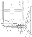
- FIG. 5 shows a partially cross-sectional lateral view of the entire plant.
- FIGS. 1 and 2 schematically show, how with a device 1 for the cleaning of flue gas tubes of a boiler plant 2 a cleaning hose positioning means 3 guides a cleaning hose 4 to a number of hose guides 5 , 6 , 7 , 8 , 9 or 5 ′, 6 ′, 7 ′, 8 ′, 9 ′.
- the hose guides 5 to 9 are arranged on a straight line 10
- the hose guides 5 ′ to 9 ′ are arranged on a circle line 11 .
- the cleaning hose positioning means 3 can be moved along the direction of arrow 12 on a straight line, in order to guide the cleaning hose 4 to the hose guides 5 to 9 .
- the cleaning hose positioning means 3 ′ however may be swivelled along arrow 13 about a point 14 , in order to guide the cleaning hose 4 ′ to the hose guides 5 ′ to 9 ′.
- FIG. 3 shows the cleaning hose positioning means 3 , which stands on a platform 16 with a base 15 .
- the base is connected to a kind of rail system so that the cleaning hose positioning means 3 moves in one axis.
- this base 15 is rotatably mounted. Rotation of the cleaning hose positioning means 3 ′ is effected via a drive motor flanged onto the frame, until the position above the desired connection piece 17 has been reached.
- the cleaning hose positioning means 3 , 3 ′ has a hose reel 37 arranged on it, which serves as a hose store 18 , and the cleaning hose 4 is guided by means of a cleaning hose conveying module 19 to a hose guide 5 to 9 .
- the cleaning hose conveying module 19 is arranged directly in front of the hose guide.
- the cleaning hose conveying module 19 comprises a feed roller 20 with a circumferential groove 21 , in which the hose 4 is guided.
- the hose 4 can be retained in the groove 21 so that when the roller 20 is rotating, a circumferential force of the roller 20 is transferred to the hose 4 . It is advantageous if a number of contact rollers 22 to 25 press the hose into the groove 21 .
- FIG. 4 shows a hose cleaning means 26 .
- a nozzle 27 is arranged at the front end of the hose 4 , which can be pushed through the hose cleaning means 26 and through the connection piece 17 into the hose guide 5 . The nozzle 27 then gets into the boiler plant 2 and from there into the flue gas tube 28 for the cleaning of heat exchange surfaces and membrane walls in there.
- the hose cleaning means 26 is used for cleaning the hose 4 and, as required, also the nozzle 27 .
- the hose cleaning means 26 is a pipe-shaped element serving as rinsing pipe 30 , which has a gas inlet 31 and a liquid inlet 32 arranged on it.
- the gas inlet 31 is in communication with a pressurised gas line (not shown), whilst the liquid inlet 32 is in communication with a cleaning liquid line such as a service water line (not shown).
- the hose 4 is initially sprayed with cleaning liquid via nozzles 33 and subsequently dried by means of pneumatic blasting. Every part of the hose 4 , during withdrawal of the same, is initially guided past a unit 34 spraying the hose with a liquid, and thereafter it is guided past a pneumatic blast unit 35 , whereafter the hose leaves the rinsing pipe 30 in a cleaned state.
- a stroke cylinder unit 36 is provided, which is arranged between the cleaning means 26 and the cleaning hose conveying module 19 .
- the hose cleaning means 26 is attached to the cleaning hose conveying module 19 .
- the cleaning module When using the device 1 for the cleaning of flue gas tubes 28 , the cleaning module is positioned with a first drive motor of the cleaning hose positioning means 3 above a connection piece 17 of a hose guide 5 .
- a second motor is provided for winding and unwinding of the hose.
- the feed roller 20 for lowering the hose 4
- the hose reel 37 of the hose store 18 for withdrawing the hose 4
- the hose reel 37 is held in position via a brake 38 .
- the hose cleaning means 26 When the hose cleaning means 26 is positioned over the desired connection piece 17 by a drive motor arranged on the frame of the hose positioning means 3 , the hose cleaning means 26 is lowered into the connection piece 17 by means of a pneumatic cylinder 36 through a slide 29 .
- the hydraulic spraying unit 34 and the pneumatic blast unit 35 act as a rinsing and drying unit. Due to their positioning in a funnel (not shown) of the connection piece 17 the rotational movement of the cleaning hose positioning means 3 is sufficiently arrested. An additional fixing in this position is not necessary. This leads to the creation of a practically closed system, which can reduce the outflow of flue gas due to e.g. deflagrations.
- a pulley wheel is then connected to a drive shaft, and using the integrated cleaning hose conveying module 19 the hose 4 is pushed with its nozzle 27 into the hose guide 5 .
- the spring-loaded contact rollers 22 to 25 press the hose 4 into the groove 21 of the feed roller 20 , so that, due to the frictional connection with the feed roller, this is pulled off the hose reel 37 .
- the feed roller 20 is driven by a drive shaft via the first coupling, a toothed belt and an angle gear. The prerequisite is that both the second coupling and the brake are open so that the hose reel is able to rotate freely.
- the cleaning hose conveying module 19 has the advantage that the hose 4 can be inserted into a hose guide 5 either vertically or horizontally. Moreover, due to the use of the cleaning hose conveying module, arcs of more than 30° with a radian measure of at least 400 to 500 mm can be employed so that constructional bottlenecks or narrow spaces in the area between the boiler roof of the boiler 2 and the platform 16 , where the hose guides are arranged, do not cause any problems.
- a first coupling is opened, so that the feed roller 20 can rotate freely.
- the hose reel 37 is connected to the drive shaft via the second coupling.
- the brake 38 is closed so that the nozzle 27 cannot drop.
- the second coupling is then opened again.
- the cleaning hose positioning means 3 can now either remain in this position or be moved to the next connection piece 17 of another hose guide 6 . It is advantageous if the cleaning hose positioning means 3 , after cleaning is finished, is moved to a defined parking position, which is at a certain connection piece usually located on the outside or in an area outside the connection pieces.
Landscapes
- Engineering & Computer Science (AREA)
- Mechanical Engineering (AREA)
- General Engineering & Computer Science (AREA)
- Chemical & Material Sciences (AREA)
- Combustion & Propulsion (AREA)
- Physics & Mathematics (AREA)
- Thermal Sciences (AREA)
- Fire-Extinguishing By Fire Departments, And Fire-Extinguishing Equipment And Control Thereof (AREA)
- Cleaning In General (AREA)
- Incineration Of Waste (AREA)
Applications Claiming Priority (4)
| Application Number | Priority Date | Filing Date | Title |
|---|---|---|---|
| DE102014004639 | 2014-04-01 | ||
| DE102014004639.7 | 2014-04-01 | ||
| DE102014004639.7A DE102014004639A1 (de) | 2014-04-01 | 2014-04-01 | Vorrichtung zum Reinigen von Rauchgaszügen einer Kesselanlage mit einem Reinigungsschlauch, einem Schlauchspeicher und einer Schlauchführung |
| PCT/DE2015/000132 WO2015149733A1 (fr) | 2014-04-01 | 2015-03-23 | Dispositif pour nettoyer des aspirations de gaz de fumée d'une installation de chaudière, comportant un tuyau de nettoyage, un réservoir de tuyau et un dispositif de guidage de tuyau |
Publications (2)
| Publication Number | Publication Date |
|---|---|
| US20170010061A1 US20170010061A1 (en) | 2017-01-12 |
| US10907913B2 true US10907913B2 (en) | 2021-02-02 |
Family
ID=53052636
Family Applications (1)
| Application Number | Title | Priority Date | Filing Date |
|---|---|---|---|
| US15/124,421 Active 2035-12-10 US10907913B2 (en) | 2014-04-01 | 2015-03-23 | Device for the cleaning of flue gas tubes of a boiler plant with a cleaning hose, a hose store and a hose guide |
Country Status (12)
| Country | Link |
|---|---|
| US (1) | US10907913B2 (fr) |
| EP (2) | EP2965032B1 (fr) |
| JP (1) | JP6627150B2 (fr) |
| AU (1) | AU2015240220B2 (fr) |
| CA (1) | CA2941848C (fr) |
| DE (2) | DE102014004639A1 (fr) |
| DK (2) | DK2965032T3 (fr) |
| ES (2) | ES2626579T3 (fr) |
| PL (2) | PL3173727T3 (fr) |
| PT (1) | PT3173727T (fr) |
| SG (2) | SG11201607471WA (fr) |
| WO (1) | WO2015149733A1 (fr) |
Families Citing this family (4)
| Publication number | Priority date | Publication date | Assignee | Title |
|---|---|---|---|---|
| CN107387621A (zh) * | 2017-06-29 | 2017-11-24 | 太仓市惠得利弹簧有限公司 | 一种用于清洁的弹簧 |
| JP7358925B2 (ja) * | 2019-11-11 | 2023-10-11 | Jfeエンジニアリング株式会社 | ボイラのダスト除去装置及びダスト除去方法 |
| CN113182292B (zh) * | 2021-05-29 | 2022-11-01 | 江苏恒源建设有限公司 | 一种市政软管内壁清理装置 |
| KR102791165B1 (ko) * | 2024-04-23 | 2025-04-04 | 주식회사 풍성 | 열교환기 튜브 세척장치 |
Citations (13)
| Publication number | Priority date | Publication date | Assignee | Title |
|---|---|---|---|---|
| GB753851A (en) | 1953-02-02 | 1956-08-01 | Ekstroems Maskinaffaer Ab | Improvements in method and apparatus for cleaning gas-swept heating surfaces with cleaning elements such as steel pellets or the like |
| US2864587A (en) | 1953-05-15 | 1958-12-16 | Ekstroems Maskinaffaer Ab | Cleaning the gas-swept heating surfaces of heat exchangers |
| US3531059A (en) * | 1968-11-26 | 1970-09-29 | Thomas J Walker | Loader,cleaner,and drier for fire hose |
| JPS5343214U (fr) | 1976-09-18 | 1978-04-13 | ||
| US4367790A (en) * | 1980-12-16 | 1983-01-11 | Draeger Walter A | Multiple tube cleaning apparatus |
| US4743175A (en) * | 1984-03-15 | 1988-05-10 | Legra Engineering Pty. Ltd. | Reel assembly for dewatering apparatus |
| US6003194A (en) * | 1997-10-03 | 1999-12-21 | Eckroth; Allan James | Hose cleaning and drying apparatus |
| US20040069331A1 (en) * | 2001-03-16 | 2004-04-15 | Garman Daniel T. | High pressure tube cleaning apparatus |
| WO2005024333A1 (fr) | 2003-09-02 | 2005-03-17 | Bruendermann Georg | Nettoyage de chaudiere |
| EP1918671A1 (fr) | 2006-11-03 | 2008-05-07 | Maxxtec AG | Dispositif de nettoyage pour un échangeur de chaleur ainsi qu'un échangeur de chaleur |
| DE202008011514U1 (de) | 2008-08-29 | 2008-11-20 | Clyde Bergemann Gmbh | Reinigungsvorrichtung für eine Verbrennungsanlage |
| DE102010051657A1 (de) | 2010-11-17 | 2012-05-24 | Clyde Bergemann Gmbh | Reinigungsvorrichtung für einen Verbrennungskessel |
| DE102011076585A1 (de) | 2011-05-27 | 2012-11-29 | Rosink Apparate- Und Anlagenbau Gmbh | Kesselreinigung |
Family Cites Families (7)
| Publication number | Priority date | Publication date | Assignee | Title |
|---|---|---|---|---|
| GB743410A (en) * | 1952-12-30 | 1956-01-18 | Ivor Power Specialty Company L | Improvements in or relating to apparatus for removing soot and other foreign matter from steam generating plant and other heat-exchangers |
| JPS62166427U (fr) * | 1986-04-14 | 1987-10-22 | ||
| JPS63294497A (ja) * | 1987-05-26 | 1988-12-01 | Kawasaki Heavy Ind Ltd | チュ−ブ内への長尺体の挿入装置 |
| US5022463A (en) * | 1990-03-08 | 1991-06-11 | Ohmstede Mechanical Services, Inc. | Multi-hose flexible lance tube cleaning system |
| DE10120338B4 (de) | 2001-04-26 | 2022-01-13 | Clyde Bergemann Gmbh | Vorrichtung zur Online-Kesselreinigung von Abfallverbrennungsanlagen |
| DE10357021A1 (de) * | 2003-12-05 | 2005-07-07 | Clyde Bergemann Gmbh | Kompakter Rußbläser |
| DE102004060884A1 (de) | 2004-12-17 | 2006-06-29 | Clyde Bergemann Gmbh | Verfahren und Vorrichtung zum Entfernen von Verbrennungsrückständen mit unterschiedlichen Reinigungsmedien |
-
2014
- 2014-04-01 DE DE102014004639.7A patent/DE102014004639A1/de not_active Withdrawn
-
2015
- 2015-03-23 EP EP15720584.0A patent/EP2965032B1/fr not_active Revoked
- 2015-03-23 PL PL16002686T patent/PL3173727T3/pl unknown
- 2015-03-23 ES ES15720584.0T patent/ES2626579T3/es active Active
- 2015-03-23 PT PT16002686T patent/PT3173727T/pt unknown
- 2015-03-23 EP EP16002686.0A patent/EP3173727B1/fr active Active
- 2015-03-23 JP JP2016554726A patent/JP6627150B2/ja active Active
- 2015-03-23 SG SG11201607471WA patent/SG11201607471WA/en unknown
- 2015-03-23 ES ES16002686T patent/ES2712999T3/es active Active
- 2015-03-23 PL PL15720584T patent/PL2965032T3/pl unknown
- 2015-03-23 DK DK15720584.0T patent/DK2965032T3/en active
- 2015-03-23 US US15/124,421 patent/US10907913B2/en active Active
- 2015-03-23 CA CA2941848A patent/CA2941848C/fr active Active
- 2015-03-23 SG SG10201808537PA patent/SG10201808537PA/en unknown
- 2015-03-23 DE DE112015001673.2T patent/DE112015001673A5/de not_active Withdrawn
- 2015-03-23 DK DK16002686.0T patent/DK3173727T3/en active
- 2015-03-23 AU AU2015240220A patent/AU2015240220B2/en active Active
- 2015-03-23 WO PCT/DE2015/000132 patent/WO2015149733A1/fr not_active Ceased
Patent Citations (16)
| Publication number | Priority date | Publication date | Assignee | Title |
|---|---|---|---|---|
| GB753851A (en) | 1953-02-02 | 1956-08-01 | Ekstroems Maskinaffaer Ab | Improvements in method and apparatus for cleaning gas-swept heating surfaces with cleaning elements such as steel pellets or the like |
| US2864587A (en) | 1953-05-15 | 1958-12-16 | Ekstroems Maskinaffaer Ab | Cleaning the gas-swept heating surfaces of heat exchangers |
| US3531059A (en) * | 1968-11-26 | 1970-09-29 | Thomas J Walker | Loader,cleaner,and drier for fire hose |
| JPS5343214U (fr) | 1976-09-18 | 1978-04-13 | ||
| US4367790A (en) * | 1980-12-16 | 1983-01-11 | Draeger Walter A | Multiple tube cleaning apparatus |
| US4743175A (en) * | 1984-03-15 | 1988-05-10 | Legra Engineering Pty. Ltd. | Reel assembly for dewatering apparatus |
| US6003194A (en) * | 1997-10-03 | 1999-12-21 | Eckroth; Allan James | Hose cleaning and drying apparatus |
| US20040069331A1 (en) * | 2001-03-16 | 2004-04-15 | Garman Daniel T. | High pressure tube cleaning apparatus |
| WO2005024333A1 (fr) | 2003-09-02 | 2005-03-17 | Bruendermann Georg | Nettoyage de chaudiere |
| US20070163629A1 (en) | 2003-09-02 | 2007-07-19 | Georg Bruendermann | Cleaning of a furnace |
| EP1918671A1 (fr) | 2006-11-03 | 2008-05-07 | Maxxtec AG | Dispositif de nettoyage pour un échangeur de chaleur ainsi qu'un échangeur de chaleur |
| DE202008011514U1 (de) | 2008-08-29 | 2008-11-20 | Clyde Bergemann Gmbh | Reinigungsvorrichtung für eine Verbrennungsanlage |
| DE102010051657A1 (de) | 2010-11-17 | 2012-05-24 | Clyde Bergemann Gmbh | Reinigungsvorrichtung für einen Verbrennungskessel |
| US20130312672A1 (en) | 2010-11-17 | 2013-11-28 | Clyde Bergemann Gmbh Maschinen-Und Apparatebau | Cleaning device for a combustion boiler |
| JP2014500943A (ja) | 2010-11-17 | 2014-01-16 | クライデ ベルゲマン ゲーエムベーハー マシーネン ウント アパラテバウ | 燃焼ボイラーのための清掃装置 |
| DE102011076585A1 (de) | 2011-05-27 | 2012-11-29 | Rosink Apparate- Und Anlagenbau Gmbh | Kesselreinigung |
Non-Patent Citations (5)
| Title |
|---|
| Clyde Bergemann GmbH proposal for Online-Cleaning-System type SCS 400-2/ES/A for Cornwall WTE Plant, dated Feb. 23, 2011. |
| English Translation of the International Preliminary Report on Patentability and Written Opinion of the International Searching Authority dated Oct. 4, 2016, in PCT/DE2015/00132. |
| German Search Report in DE 10 2014 004 6397, dated Aug. 11, 2014, with English translation of relevant parts. |
| International Search Report of PCT/DE2015/000132, dated Aug. 28, 2015. |
| Japanese Office Action in JP 2016-554726, dated Jul. 24, 2018. |
Also Published As
| Publication number | Publication date |
|---|---|
| DK3173727T3 (en) | 2019-03-18 |
| EP3173727A2 (fr) | 2017-05-31 |
| AU2015240220A1 (en) | 2016-09-29 |
| SG10201808537PA (en) | 2018-11-29 |
| EP2965032B1 (fr) | 2017-03-15 |
| ES2626579T3 (es) | 2017-07-25 |
| DE112015001673A5 (de) | 2016-12-22 |
| PT3173727T (pt) | 2019-03-19 |
| JP6627150B2 (ja) | 2020-01-08 |
| EP2965032A1 (fr) | 2016-01-13 |
| SG11201607471WA (en) | 2016-10-28 |
| WO2015149733A1 (fr) | 2015-10-08 |
| DE102014004639A1 (de) | 2015-10-01 |
| EP3173727B1 (fr) | 2018-11-28 |
| US20170010061A1 (en) | 2017-01-12 |
| JP2017516050A (ja) | 2017-06-15 |
| PL3173727T3 (pl) | 2019-05-31 |
| PL2965032T3 (pl) | 2017-08-31 |
| CA2941848A1 (fr) | 2015-10-08 |
| EP3173727A3 (fr) | 2017-10-25 |
| CA2941848C (fr) | 2022-04-12 |
| AU2015240220B2 (en) | 2019-01-17 |
| ES2712999T3 (es) | 2019-05-17 |
| DK2965032T3 (en) | 2017-06-12 |
Similar Documents
| Publication | Publication Date | Title |
|---|---|---|
| US10907913B2 (en) | Device for the cleaning of flue gas tubes of a boiler plant with a cleaning hose, a hose store and a hose guide | |
| US10315856B2 (en) | Cleaning device and method for cleaning a screw conveyor | |
| CN106794491B (zh) | 柔性清洁枪定位器引导设备 | |
| ES2601027T3 (es) | Procedimiento y dispositivo de decapado de tubos por acción de un fluido a presión muy alta | |
| US20200139555A1 (en) | Apparatus for Cleaning Industrial Plants | |
| US11904368B2 (en) | Device and method for cleaning containers | |
| CN1846112B (zh) | 炉子清洁装置 | |
| CN102105763A (zh) | 吹灰设备 | |
| JP6282744B2 (ja) | パイプ片のための洗浄装置 | |
| JPH08504262A (ja) | 熱交換面用清掃装置およびそのための改良されたノズル | |
| US9651322B2 (en) | Cleaning device for a combustion boiler | |
| US7165564B2 (en) | Device for cleaning installations and related methods | |
| US5078162A (en) | Cleaning apparatus for tubes | |
| CN217121130U (zh) | 一种复合管内管的外壁处理设备 | |
| RU2519846C1 (ru) | Устройство для очистки и сушки прокатных клетей | |
| CN111023278B (zh) | 清洗机构及具有其的空调室内机 | |
| RU2702435C1 (ru) | Система для очистки фасадов высотных зданий | |
| CN121446765A (zh) | 一种大型风电轴承保持架自动清洗防锈设备及方法 | |
| CN121470278A (zh) | 一种集成式线材酸洗检测全流程自动化远程判样系统 | |
| GB2512644A (en) | Applicator machine | |
| CN105214901A (zh) | 用于阳极棒快速涂刷和干燥的设备 | |
| EA044719B1 (ru) | Устройство для очистки труб |
Legal Events
| Date | Code | Title | Description |
|---|---|---|---|
| AS | Assignment |
Owner name: MARTIN GMBH FUER UMWELT- UND ENERGIETECHNIK, GERMANY Free format text: ASSIGNMENT OF ASSIGNORS INTEREST;ASSIGNORS:STRAMKA, CLAUDIA;DRAEGER, RALF;SIGNING DATES FROM 20160825 TO 20160826;REEL/FRAME:039674/0756 Owner name: MARTIN GMBH FUER UMWELT- UND ENERGIETECHNIK, GERMA Free format text: ASSIGNMENT OF ASSIGNORS INTEREST;ASSIGNORS:STRAMKA, CLAUDIA;DRAEGER, RALF;SIGNING DATES FROM 20160825 TO 20160826;REEL/FRAME:039674/0756 |
|
| STPP | Information on status: patent application and granting procedure in general |
Free format text: ADVISORY ACTION MAILED |
|
| STPP | Information on status: patent application and granting procedure in general |
Free format text: DOCKETED NEW CASE - READY FOR EXAMINATION |
|
| STPP | Information on status: patent application and granting procedure in general |
Free format text: NON FINAL ACTION MAILED |
|
| STPP | Information on status: patent application and granting procedure in general |
Free format text: RESPONSE TO NON-FINAL OFFICE ACTION ENTERED AND FORWARDED TO EXAMINER |
|
| STPP | Information on status: patent application and granting procedure in general |
Free format text: FINAL REJECTION MAILED |
|
| STPP | Information on status: patent application and granting procedure in general |
Free format text: DOCKETED NEW CASE - READY FOR EXAMINATION |
|
| STPP | Information on status: patent application and granting procedure in general |
Free format text: NON FINAL ACTION MAILED |
|
| STPP | Information on status: patent application and granting procedure in general |
Free format text: PUBLICATIONS -- ISSUE FEE PAYMENT VERIFIED |
|
| STCF | Information on status: patent grant |
Free format text: PATENTED CASE |
|
| CC | Certificate of correction | ||
| MAFP | Maintenance fee payment |
Free format text: PAYMENT OF MAINTENANCE FEE, 4TH YEAR, LARGE ENTITY (ORIGINAL EVENT CODE: M1551); ENTITY STATUS OF PATENT OWNER: LARGE ENTITY Year of fee payment: 4 |