US11218044B2 - Rotor for an asynchronous electrical machine having an end shaft - Google Patents
Rotor for an asynchronous electrical machine having an end shaft Download PDFInfo
- Publication number
- US11218044B2 US11218044B2 US16/575,327 US201916575327A US11218044B2 US 11218044 B2 US11218044 B2 US 11218044B2 US 201916575327 A US201916575327 A US 201916575327A US 11218044 B2 US11218044 B2 US 11218044B2
- Authority
- US
- United States
- Prior art keywords
- retention
- short
- magnetic block
- rotor
- circuit
- Prior art date
- Legal status (The legal status is an assumption and is not a legal conclusion. Google has not performed a legal analysis and makes no representation as to the accuracy of the status listed.)
- Active, expires
Links
Images




Classifications
-
- H—ELECTRICITY
- H02—GENERATION; CONVERSION OR DISTRIBUTION OF ELECTRIC POWER
- H02K—DYNAMO-ELECTRIC MACHINES
- H02K1/00—Details of the magnetic circuit
- H02K1/06—Details of the magnetic circuit characterised by the shape, form or construction
- H02K1/22—Rotating parts of the magnetic circuit
- H02K1/28—Means for mounting or fastening rotating magnetic parts on to, or to, the rotor structures
-
- H—ELECTRICITY
- H02—GENERATION; CONVERSION OR DISTRIBUTION OF ELECTRIC POWER
- H02K—DYNAMO-ELECTRIC MACHINES
- H02K1/00—Details of the magnetic circuit
- H02K1/06—Details of the magnetic circuit characterised by the shape, form or construction
- H02K1/22—Rotating parts of the magnetic circuit
-
- H—ELECTRICITY
- H02—GENERATION; CONVERSION OR DISTRIBUTION OF ELECTRIC POWER
- H02K—DYNAMO-ELECTRIC MACHINES
- H02K1/00—Details of the magnetic circuit
- H02K1/06—Details of the magnetic circuit characterised by the shape, form or construction
- H02K1/22—Rotating parts of the magnetic circuit
- H02K1/28—Means for mounting or fastening rotating magnetic parts on to, or to, the rotor structures
- H02K1/30—Means for mounting or fastening rotating magnetic parts on to, or to, the rotor structures using intermediate parts, e.g. spiders
-
- H02K17/165—
-
- H—ELECTRICITY
- H02—GENERATION; CONVERSION OR DISTRIBUTION OF ELECTRIC POWER
- H02K—DYNAMO-ELECTRIC MACHINES
- H02K17/00—Asynchronous induction motors; Asynchronous induction generators
- H02K17/02—Asynchronous induction motors
- H02K17/16—Asynchronous induction motors having rotors with internally short-circuited windings, e.g. cage rotors
- H02K17/168—Asynchronous induction motors having rotors with internally short-circuited windings, e.g. cage rotors having single-cage rotors
-
- H—ELECTRICITY
- H02—GENERATION; CONVERSION OR DISTRIBUTION OF ELECTRIC POWER
- H02K—DYNAMO-ELECTRIC MACHINES
- H02K17/00—Asynchronous induction motors; Asynchronous induction generators
- H02K17/02—Asynchronous induction motors
- H02K17/16—Asynchronous induction motors having rotors with internally short-circuited windings, e.g. cage rotors
- H02K17/18—Asynchronous induction motors having rotors with internally short-circuited windings, e.g. cage rotors having double-cage or multiple-cage rotors
-
- H—ELECTRICITY
- H02—GENERATION; CONVERSION OR DISTRIBUTION OF ELECTRIC POWER
- H02K—DYNAMO-ELECTRIC MACHINES
- H02K7/00—Arrangements for handling mechanical energy structurally associated with dynamo-electric machines, e.g. structural association with mechanical driving motors or auxiliary dynamo-electric machines
- H02K7/003—Couplings; Details of shafts
-
- H—ELECTRICITY
- H02—GENERATION; CONVERSION OR DISTRIBUTION OF ELECTRIC POWER
- H02K—DYNAMO-ELECTRIC MACHINES
- H02K15/00—Processes or apparatus specially adapted for manufacturing, assembling, maintaining or repairing of dynamo-electric machines
- H02K15/02—Processes or apparatus specially adapted for manufacturing, assembling, maintaining or repairing of dynamo-electric machines of stator or rotor bodies
- H02K15/021—Magnetic cores
- H02K15/023—Cage rotors
Definitions
- This invention relates to asynchronous rotating electrical machines having a cage winding, and relates more particularly to a device for immobilizing sheets incorporated into a rotor of the machine comprising an end shaft.
- This invention also relates to a rotating electrical machine comprising such a rotor.
- a rotor of an asynchronous rotating electrical machine comprises a laminated rotor intended to operate at high rotational velocities, particularly up to a peripheral velocity of 300 m/s, and comprises an end shaft such that the magnetic sheets of the rotor do not contain any holes at their center in order to minimize the mechanical stresses that, in the case of a rotor comprising an end shaft, concentrate around the holes and are susceptible to damage the sheets of the magnetic circuit.
- the document EP0609645 describes a laminated rotor comprising an end shaft for an asynchronous electric motor.
- FIG. 1 depicts a cross-section of such a rotor 1 in an axial direction.
- the rotor comprises two half-shafts 2 and 3 between which magnetic sheets 4 are inserted, kept compact by anchors 5 connecting the two half-shafts 2 and 3 .
- the magnetic sheets 4 form the magnetic mass of the rotor.
- the rotor 1 respectively comprises short-circuit rings or discs 2 a and 3 a connecting the conductive bars (not shown), e.g. made of copper, forming a cage winding.
- Each magnetic sheet 4 comprises holes 4 a in which the anchors 5 are inserted, and generally has a thickness between one-tenth of a millimeter and one millimeter.
- Each sheet 4 is coated with a layer of insulating varnish 6 preventing electrical contact between adjacent sheets, so as to minimize Foucault current losses and increase the motor's efficiency.
- the holes 4 a are designed such that the rods 5 can be inserted into the holes 4 a of all of the sheets 4 stacked during the construction of the rotor, and such that there is still clearance to absorb the increase in the diameter of the anchors caused by the effect of heat when the rotor is operating.
- the magnetic sheets 4 are kept in position relative to one another by shear adhesion caused by the compacting of the sheets, the presence of roughness of the surface of the magnetic sheets, and the electrically insulating varnish.
- the rotor when the motor is operating, the rotor is subjected to vibrations, impacts, and heating.
- the asynchronous rotating electrical machine may be used in a chemically aggressive environment, leading the varnish on the magnetic sheets to deteriorate, such as when the electrical machine is used and incorporated into a motor-compressor.
- the rotor is cooled by gas containing impurities and/or aggressive chemicals that eat away at the varnish before its compression and could damage the magnetic sheets.
- the two half-shafts are no longer coaxial as shown in FIG. 2 , causing significant rotor vibrations that could cause an emergency shutdown of the rotor, or even its destruction.
- the document DE19956042 discloses a rotor having an end shaft for an asynchronous rotating electrical machine comprising a magnetic block formed by a stack of metal plates compacted between two half-shafts.
- the metal plates have a thickness greater than that of the metal sheets.
- the plates are less vulnerable to chemical aggression.
- Centrifugal force, or shocks and vibrations, could cause the sheets to move in a radial direction.
- the document DE573512 discloses a rotor for a turbogenerator comprising a magnetic block made of metal plates stacked and welded together.
- Each sheet comprises a pin protruding out from a first face and a cavity formed in a second face, the pin and the cavity respectively cooperating with a cavity and pin of the adjacent sheets.
- this rotor is not suitable for an asynchronous rotating electrical machine.
- the magnetic circuit is held in place by welding metal plates to one another, and not by compacting between two half-shafts using anchors or screws.
- EP0509119 discloses a rotor for an asynchronous rotating electrical machine comprising a magnetic block formed by a stack of welded sheets.
- the sheets have a shaft passing through them.
- JPH104658 and WO2018037486 disclose a rotor for an asynchronous rotating electrical machine comprising a single-part magnetic block through which a shaft passes.
- a rotor for an asynchronous electrical machine is formed of a shaft into which copper elements are inserted to form a cage winding via a hot isostatic pressing process.
- furnaces are not suitable for large rotors, such as those a meter in outer diameter and six meters in length.
- a rotor for an asynchronous electrical machine having an end shaft comprising two half-shafts pressing against a cylindrical magnetic block and two short-circuit discs each placed between one half-shaft and one of the ends of the cylindrical magnetic block.
- Each half-shaft comprises at least one first means of retention
- each short-circuit disc comprises on each of its faces at least one second means of retention
- each end of the magnetic block comprises at least one third means of retention, the first, second, and third means of retention mating with one another in such a way as to prevent the short-circuit discs from moving relative to the half-shafts and relative to the magnetic block.
- anchors are distributed uniformly across at least one diameter of the rotor, so as to keep the magnetic block and the short-circuit discs compacted between the half-shafts.
- screws are distributed uniformly across a diameter of the half-shafts passing through the short-circuit discs and trapped within the magnetic block such that the half-shafts fit around the short-circuit discs and the magnetic block.
- the first, second, and third means of retention are disposed in the center of the short-circuit disc, the half-shaft, and the magnetic block.
- the first, second, and third means of retention are disposed uniformly or substantially uniformly on the same diameter of the short-circuit disc, the half-shaft, and the magnetic block.
- the first means of retention and the third means of retention each comprise a counterbore and the second means of retention comprises a retention pin intended to fit into the counterbore.
- the short-circuit disc and the retention pin have a hole in their center.
- the first means of retention and the third means of retention each comprise a retention pin and the second means of retention comprises a counterbore intended to accommodate the retention pin.
- the first means of retention comprises a retention pin
- the third means of retention comprises a counterbore
- the second means of retention of a first face of the short-circuit disc comprises a counterbore
- the second means of retention of a second face of the short-circuit disc comprises a retention pin, such that each retention pin fits into an adjacent counterbore.
- the rotor further comprises at least one removable retention pin, the first, second, and third means of retention each comprising a counterbore mating with the removable retention pin.
- the rotor further comprises at least one removable retention pin
- the first means of retention comprises a blind hole created in the half-shaft
- the second means of retention comprises a hole created in the short-circuit disc such that the hole passes through the short-circuit disc
- the third means of retention comprises a hole created in the magnetic block such that the hole passes through the magnetic block, the removable retention pin fitting into the holes with or without clearance.
- the retention pin or the removable retention pin is circular in a cylindrical, polygonal, or conical shape, and preferably square, triangular, or square topped by a triangle.
- the magnetic block comprises a single-part metal body.
- the magnetic block comprises a stack of metal plates, each metal plate comprising on each of its faces a means of retention, the adjacent means of retention being intended to mate with one another so as to prevent a metal plate from moving relative to the adjacent elements comprising a metal plate or a short-circuit disc.
- the rotor further comprises screws distributed in the metal plates comprising counterbores so as to rigidly connect adjacent metal plates, the screw heads being housed in the counterbores.
- an electrical insulator is inserted between the half-shaft and the short-circuit disc and/or inserted between the metal plates.
- the rotor further comprises bars inserted uniformly across the same diameter of the magnetic block, the retention pin or removable retention pin being polygonal in shape and disposed at the center of the magnetic block, the number of faces of the polygon being a multiple of the number of bars and anchors.
- the means of retention are disposed uniformly across at least one diameter of the magnetic block.
- the first, second, and third means of retention are of different types.
- an asynchronous rotating electrical machine having a cage winding comprising a rotor as defined previously.
- FIGS. 1 and 2 already mentioned, illustrate a rotor comprising an end shaft of a rotating electrical machine according to the state of the art
- FIG. 3 illustrates an embodiment of an asynchronous rotating electrical machine
- FIG. 4 illustrates a cross-section of a first embodiment of the rotor in an axial direction
- FIG. 5 illustrates a partial cross-section of a second embodiment of the rotor in an axial direction
- FIG. 6 illustrates a partial cross-section of a third embodiment of the rotor in an axial direction
- FIG. 7 illustrates a partial cross-section of a fourth embodiment of the rotor in an axial direction
- FIG. 8 illustrates a partial cross-section of a fifth embodiment of the rotor in an axial direction
- FIG. 9 illustrates a partial cross-section of a sixth embodiment of the rotor in an axial direction
- FIG. 10 illustrates a cross-section of a seventh embodiment of the rotor in an axial direction
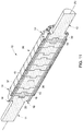
- FIG. 11 illustrates a cross-section of an eighth embodiment of the rotor in an axial direction
- FIG. 12 illustrates a partial cross-section of a ninth embodiment of the rotor in an axial direction
- FIG. 13 illustrates a partial cross-section of a tenth embodiment of the rotor in an axial direction
- FIG. 14 illustrates an embodiment of metal plates held in place by screws
- FIGS. 15 and 16 illustrate an eleventh embodiment of the rotor
- FIGS. 17 to 19 illustrate embodiments of the short-circuit disc.
- FIG. 3 illustrates one embodiment of an asynchronous rotating electrical machine 7 comprising a stator 8 , bearings 9 , and a rotor 10 inserted into the stator 8 and bearings 9 .
- the rotor 10 comprises a rotor end shaft comprising two half-shafts 11 and 12 and an axis (A) conflated with the axis of rotation of the rotor 10 .
- the rotor 10 further comprises a magnetic block 13 , and two short-circuit discs 14 each placed between one end of the magnetic block 13 and a half-shaft 11 , 12 .
- Bars 15 are inserted uniformly along a single diameter in the magnetic block 13 .
- the bars 15 and short-circuit discs 14 are made, for instance, of copper, and are electrically linked to one another to form a cage winding.
- the magnetic block 13 comprises a single-part metal body made, for instance, of steel.
- Anchors 16 are distributed uniformly across at least one diameter of the rotor, so as to keep the magnetic block 13 and the short-circuit discs 14 compacted between the two half-shafts 11 and 12 .
- the ends of the anchors 16 comprise a thread in order to receive a nut.
- the magnetic block 13 , short-circuit discs 14 and half-shafts 11 and 12 comprise through-holes for the anchors 16 , sized such that when the rotor heats up, the anchors can thermally expand, while also allowing the anchors to fit with clearance into the magnetic block.
- Each half-shaft 11 and 12 comprises at least one means of retention
- each short-circuit disc 14 comprises on each of its faces at least a second means of retention
- each end of the magnetic block comprises at least one third means of retention.
- the first, second, and third means of retention mate with one another so as to prevent a short-circuit disc 14 from moving relative to the half-shafts 11 and 12 and relative to the magnetic block 13 .
- the first, second, and third means of retention are disposed respectively in the center of the half-shaft 11 and 12 , the center of the short-circuit disc 14 , and the center of the magnetic block 13 .
- the first and third means of retention comprise a counterbore 17 , 20 and the second means of retention comprise a retention pin 18 , the pins 18 and counterbores 17 and 20 are sized so that the pin 18 fits into the counterbore 17 , 20 with or without clearance.
- FIG. 5 illustrates a partial cross-section of a second embodiment of the rotor 10 in an axial direction.
- the magnetic block 13 , the short-circuit disc 14 , the bars 15 , the anchors 16 , the retention pins 18 , and the counterbores 20 can be seen.
- an electrical insulator 21 separates the magnetic block 13 and the short-circuit disc 14 on part of their contact surface.
- the electrical insulator 21 is made up of a ring having a hole facing each pin 18 to allow through the pin 18 and of a disc facing each pin 18 .
- the electrical insulator is an insulating varnish deposited on a thin sheet, such as one made of steel, the thin sheet comprising a ring, and a disc facing each pin 18 being inserted between the magnetic mass 13 and the short-circuit disc 14 .
- the insulator 21 comprising an insulating ring and an insulating disc facing each pin 18 , or an insulating varnish deposited on a thin sheet, is inserted between each metal plate as depicted in FIGS. 10 to 14 , which limits the leakage currents in order to improve the efficiency of the rotating electrical machine 7 .
- the partial electrical insulation between the magnetic mass 13 and the short-circuit discs 14 makes it possible to reduce leakage currents.
- the efficiency of the rotating electrical machine 7 is improved.
- FIG. 6 illustrates a partial cross-section of a third embodiment of the rotor 10 in an axial direction.
- the magnetic block 13 , the bars 15 , the anchors 16 , the retention pins 23 , and the counterbores 20 can be seen.
- the short-circuit disc 14 has a hole in its center
- the second means of retention of the short-circuit disc 14 comprises a retention pin 23 having a hole in its center so as to form two retention collars each intended to fit with or without clearance into the counterbore 20 .
- This lessening makes it possible to increase the value of the critical bending speed of the rotor 10 , which makes it possible to increase the running velocity of the rotating electrical machine 7 and as a result its electrical power.
- screws 24 are distributed uniformly on a diameter of the half-shafts 11 and 12 and pass through short-circuit discs 14 .
- the screws 24 are trapped in the magnetic block 13 such that the half-shafts 11 and 12 fit around the short-circuit discs 14 and the magnetic block 13 .
- the first means of retention and the third means of retention each comprise a retention pin 25 and 27
- the second means of retention comprises a counterbore 26 .
- the retention pins 25 and 27 and the counterbore 26 are sized so that the retention pins fit into a counterbore.
- FIG. 9 illustrates a sixth embodiment of the rotor 10 .
- the first means of retention comprises a retention pin 28
- the third means of retention comprises a counterbore 31
- the second means of retention of a first face of the short-circuit disc comprises a counterbore 29
- the second means of retention of a second face of the short-circuit disc comprises a retention pin 30 .
- the retention pin 28 of the half-shaft 11 , the counterbore 29 , and the retention pin 30 of the short-circuit disc, and the counterbore 31 of the magnetic block 13 are sized so that the retention pins each fit into a counterbore with or without clearance.
- FIG. 10 illustrates a cross-section of a seventh embodiment of the rotor 10 in an axial direction.
- the half-shafts 11 and 12 comprising the counterbores 20 , the short-circuit discs 14 comprising the retention pins 18 , the bars 15 , and the anchors 16 can be seen.
- the rotor 10 comprises a magnetic block 32 comprising a stack of metal plates 33 and 34 .
- the metal plate referenced as 34 is located at one of the ends of the magnetic plate 32 .
- Each metal plate 33 and 34 comprises a means of retention on each of its faces.
- the means of retention of the plate referenced as 33 comprise on a first face of said plate a counterbore 35 and on a second face a retention pin 36 , such that the retention pin 36 fits with or without clearance into an adjacent counterbore 35 such that, for a plate 33 located at the end of the magnetic block 32 , the retention pin 18 of the short-circuit disc 14 fits with or without clearance into a counterbore 35 of said plate 33 .
- the means of retention of the first and second faces of the metal plate are able to mate with or without clearance with the means of retention of the adjacent plates so as to prevent the metal plate from moving relative to the adjacent metal plates 33 , 34 .
- the plate referenced as 34 comprises on each of its faces a counterbore 35 so that the retention pin 18 and 36 fits with or without clearance into an adjacent counterbore 35 .
- the plate referenced as 34 comprises the third means of retention mating with the second means of retention of the short-circuit disc 14 comprising the pin 18 so as to prevent the metal plate referenced as 34 from moving relative to an adjacent element comprising the metal plate referenced as 33 or the short-circuit disc 14 .
- the rotor 10 comprises a magnetic block 36 comprising a stack of metal plates 37 and 38 , alternating with one another.
- the metal plates 37 and 38 each comprise on their first and second faces an identical means of retention.
- the means of retention of the plates referenced as 37 comprise a counterbore on each face and the means of retention of the plates referenced as 38 comprise a pin on each face.
- the plates referenced as 37 and 38 are stacked in alternating fashion so that a pin fits with or without clearance into an adjacent counterbore and so that the third means of retention of the plates 37 at the end of the magnetic block mate with the second means of retention of the short-circuit disc 14 so as to prevent a metal plate from moving relative to an adjacent element comprising a metal plate 37 , 38 or the short-circuit disc 14 .
- the rotor 10 comprises a magnetic block 39 comprising a stack of metal plates 40 .
- Each metal plate 40 comprises on each of its faces a means of retention comprising a counterbore 41 accommodating with or without clearance a removable retention pin 42 so as to prevent the metal plate from moving relative to the adjacent metal plates.
- the plates 40 located at the ends of the magnetic block 39 each comprise the third means of retention mating with the second means of retention of the short-circuit disc 14 so as to prevent the metal plate from moving relative to the short-circuit disc 14 .
- the first, second, and third means of retention each comprise a counterbore identical to the counterbore 41 accommodating a removable retention pin 42 .
- the removable retention pin 42 may, if it is rigidly connected to one or both faces of a metal plate 40 , be bonded to the plate or shrink-fitted into the counterbore 41 of the plate. If the pin is shrink-fitted, the temperature differential needed for the shrink-fitting is achieved either by heating the plate, or preferably by cooling the removable pin, e.g. by plunging the pin into liquid nitrogen.
- the first, second, and third means of retention may be of different types.
- FIG. 13 illustrates a partial cross-section of a tenth embodiment of the rotor 10 in an axial direction.
- the rotor 10 comprises a magnetic block 43 comprising a stack of metal plates 44 .
- Each metal plate 44 comprises through-holes 45 so that each hole 45 mates with or without clearance with a removable retention pin 46 so as to prevent a metal plate 44 from moving relative to the adjacent metal plates.
- the plates 44 located at the ends of the magnetic block 43 each comprise the third means of retention comprising a hole 45 mating with the second means of retention of the short-circuit disc 14 so as to prevent the metal plate from moving relative to the short-circuit disc 14 .
- the first means of retention comprises a blind hole 48
- the second means of retention comprises a hole 49 such that the hole 49 passes through the short-circuit disc 14
- a removable retention pin 50 fitting with or without clearance into the holes referenced as 45 , 48 , and 49 .
- the first, second, and third means of retention may be of different types.
- the retention pins referenced as 46 and 50 are replaced by a rod 47 fitting with or without clearance into the holes 45 , 49 and housed in the blind holes 48 .
- the metal plates are held in place in the axial direction (A) by anchors.
- the metal plates are screwed to one another.
- the metal plates 51 , 52 and 53 can be held in place by screws.
- the plates 51 and 52 each comprise a counterbore 54 in order to fit the heads of the screws 56 into the thickness of the plate, and the plates 52 and 53 each comprise a threaded hole 55 .
- Screws 56 rigidly connect the plates 51 , 52 and 53 to one another by being screwed into the threaded holes 55 .
- the number and location of the screws are determined such that a metal plate does not move relative to the other metal plates when the rotor 10 is rotationally driven and subjected to a torque or overtorque applied to its half-shafts.
- Each plate 51 , 52 , 53 comprises, in alternating fashion, counterbores 54 for allowing through screws 56 and threaded holes 55 mating with the threaded parts of the screws 56 . This way, each plate is fastened by screws and rigidly connected to the adjacent plates.
- the metal plates are rigidly connected by compacting with anchors linking the two plates located at the ends of the magnetic block, the plates having holes for allowing the anchors through, and the two end plates comprising counterbores for receiving the nuts at the ends of the anchors, or one or two plates comprising threaded holes receiving the threaded ends of the anchors.
- the magnetic block is fastened by screws to the half-shafts as shown in FIG. 7 .
- the metal plates may be of the same thickness or of different thicknesses.
- the thickness of the metal plates is chosen so that it is greater than 40% of the thickness of the short-circuit disc 14 and greater than 5% of the outer diameter of the rotor 10 , preferably from 15 to 60% of the outer diameter of the rotor.
- means of retention are disposed uniformly across at least one diameter of the magnetic block.
- FIGS. 15 and 16 illustrate a partial cross-section of an eleventh embodiment of the rotor 10 in an axial direction and a front view of the short-circuit disc 14 in the direction XVI.
- the half-shaft 12 comprising blind holes 48 , the short-circuit disc 14 comprising through-holes 49 , and removable retention pins 57 can be seen.
- the three removable retention pins 57 are cylindrical and are disposed on the same diameter of the short-circuit disc 14 ; in variants not shown, there may also be 2, 4, 5, or more retention pins machined in the half-shafts or metal plates or short-circuit discs or removable pins, substantially distributed uniformly across the same diameter, or in two or more rows with two or more concentric diameters.
- the retention pins and removable retention pins may, for instance, be circular, in a shape that is cylindrical or conical, square, rhomboid, triangular, trapezoidal, square topped by a triangle, or polygonal.
- FIGS. 17 and 18 illustrate a front view of the short-circuit disc 14 comprising the second means of retention at its center, or a front view of a half-shaft 11 , 12 or a metal plate 13 , 33 , 34 , 37 , 38 , 40 , 44 , 51 , 52 , 53 of the magnetic block.
- FIG. 17 illustrates, for instance, the first means of retention comprising a machined or removable square retention pin 58 and the second means of retention comprising a square hole 59 accommodating the retention pin 58 with or without clearance J.
- the anchors 16 pass through the short-circuit discs 14 , half-shafts or metal plates.
- the number of sides of the pin 58 is a multiple of the number of copper bars 15 (not shown in FIG. 17 ) and anchors 16 , thereby enabling multiple angular positions of the half-shaft or short-circuit disc or metal plates, when stacking and manufacturing the rotor.
- a four-sided square pin is a multiple of eight anchors, or as shown in FIG. 18 , a three-sided triangular pin is multiple and compatible with six anchors.
- this configuration makes it possible to avoid using positioning guides when installing the rotor.
- such a retention pin makes it possible to transmit a sizable torque between the short-circuit disc 14 and the half-shaft, or between metal plates, via the sides of the polygon.
- the machined or removable retention pin may be an asymmetrical polygon, such as, for instance, a square topped with a triangle, making it possible to use it as a positioning guide as well as a unique angular position if need be for the half-shaft, short-circuit disc, or metal plates.
- the compacting force of the anchors may be reduced because the torque only travels through the surfaces of the plates in contact.
- the number of anchors may be reduced, or the cross-section of the anchors may be reduced in the case of a rotor comprising anchors.
- polygonal retention pins enable the rotor to transmit a much higher torque than an adhesion torque transmission between adjacent elements such as half-shafts, short-circuit discs, or metal plates.
- FIG. 18 illustrates the first means of retention comprising a machined or removable triangular pin 60 and the corresponding second or third means of retention comprising a triangular hole 61 accommodating the pin 60 with or without clearance J 1 , and the anchors 16 .
- the number of sides of the pin 60 is a multiple of the number of anchors 16 and copper bars 15 (not shown in FIG. 18 ).
- a threaded end of the anchors 16 is screwed into a threaded hole of the half-shaft 11 or 12 , and the other end of the anchors passes through a hole in the half-shaft 12 or 11 to accommodate a nut.
- FIG. 19 illustrates a variant embodiment having two or more rows of copper bars 15 disposed along two or more substantially concentric diameters, or two or more rows of anchors 16 or fastening screws 24 , 56 disposed along two or more substantially concentric diameters.
- the bars 15 are rectangular in shape, rectangular with rounded edges, or oblong in shape.
- the bars 15 are preferably made of copper or a copper alloy, but may also be made of aluminum, an aluminum alloy, or any other electrically conductive material.
Landscapes
- Engineering & Computer Science (AREA)
- Power Engineering (AREA)
- Iron Core Of Rotating Electric Machines (AREA)
- Induction Machinery (AREA)
- Permanent Field Magnets Of Synchronous Machinery (AREA)
- Connection Of Motors, Electrical Generators, Mechanical Devices, And The Like (AREA)
Applications Claiming Priority (2)
| Application Number | Priority Date | Filing Date | Title |
|---|---|---|---|
| FR1858468 | 2018-09-19 | ||
| FR1858468A FR3086121B1 (fr) | 2018-09-19 | 2018-09-19 | Rotor pour machine electrique asynchrone a arbre non traversant |
Publications (2)
| Publication Number | Publication Date |
|---|---|
| US20200112214A1 US20200112214A1 (en) | 2020-04-09 |
| US11218044B2 true US11218044B2 (en) | 2022-01-04 |
Family
ID=65201528
Family Applications (1)
| Application Number | Title | Priority Date | Filing Date |
|---|---|---|---|
| US16/575,327 Active 2040-03-17 US11218044B2 (en) | 2018-09-09 | 2019-09-18 | Rotor for an asynchronous electrical machine having an end shaft |
Country Status (4)
| Country | Link |
|---|---|
| US (1) | US11218044B2 (de) |
| EP (1) | EP3627659B1 (de) |
| CN (1) | CN110932438A (de) |
| FR (1) | FR3086121B1 (de) |
Cited By (4)
| Publication number | Priority date | Publication date | Assignee | Title |
|---|---|---|---|---|
| US20220010734A1 (en) * | 2020-07-08 | 2022-01-13 | Ge Energy Power Conversion Technology Limited | Mechanical drive system and associated motor compressor |
| US20240003404A1 (en) * | 2011-09-18 | 2024-01-04 | City, University of London | Flywheel assembly |
| US11888365B2 (en) | 2018-12-14 | 2024-01-30 | Ge Energy Power Conversion Technology Limited | Conductor bar and associated rotor and rotating electrical machine |
| US11923735B2 (en) | 2018-12-14 | 2024-03-05 | Ge Energy Power Conversion Technology Limited | Rotor with non-through shaft and associated rotary electric machine |
Families Citing this family (3)
| Publication number | Priority date | Publication date | Assignee | Title |
|---|---|---|---|---|
| EP3890163A1 (de) * | 2020-04-01 | 2021-10-06 | GE Energy Power Conversion Technology Ltd. | Dimensionierungsverfahren eines rotors mit nicht durchgehender welle, entsprechender rotor und entsprechendes kompressoraggregat |
| EP4483073A1 (de) * | 2022-02-23 | 2025-01-01 | Levistor Ltd | Schwungrad |
| EP4318887A1 (de) | 2022-08-05 | 2024-02-07 | GE Energy Power Conversion Technology Ltd | Rotor und zugehörige elektrische drehmaschine |
Citations (1)
| Publication number | Priority date | Publication date | Assignee | Title |
|---|---|---|---|---|
| US5512792A (en) * | 1993-02-05 | 1996-04-30 | Bawin; Pierre | Electric motor with high power and high rotational speed |
Family Cites Families (16)
| Publication number | Priority date | Publication date | Assignee | Title |
|---|---|---|---|---|
| GB364027A (en) * | 1929-11-02 | 1931-12-28 | Bbc Brown Boveri & Cie | Improvements in rotors for high speed machines |
| DE573512C (de) | 1929-11-03 | 1933-04-03 | Bbc Brown Boveri & Cie | Laeufer fuer Turbogeneratoren, der aus axial nebeneinandergereihten vollen Scheiben zusammengesetzt ist |
| GB523311A (en) * | 1937-12-30 | 1940-07-11 | British Thomson Houston Co Ltd | Improvements in and relating to rotors for dynamo electric machines |
| DE920139C (de) * | 1948-10-02 | 1954-11-15 | Siemens Ag | Wellenloser Plattenlaeuferkoerper |
| DE2238755A1 (de) * | 1972-08-05 | 1974-02-14 | Licentia Gmbh | Ankerblechpaket fuer eine elektrische maschine |
| US4644210A (en) | 1985-12-12 | 1987-02-17 | Rockwell International Corporation | High speed induction motor with squirrel cage rotor |
| EP0509119A1 (de) | 1991-04-18 | 1992-10-21 | Asea Brown Boveri Ag | Rotor einer Asynchronmaschine |
| DE69311530T2 (de) | 1993-02-05 | 1998-01-08 | Gec Alsthom Acec En Sa | Elektrischer Asynchronmotor mit hoher Drehgeschwindigkeit und hoher Leistung |
| JPH104658A (ja) | 1996-06-13 | 1998-01-06 | Hitachi Ltd | 誘導電動機 |
| DE19956042A1 (de) | 1999-11-22 | 2001-05-23 | Abb Ind Ag Baden | Rotor für eine schnellaufende elektrische Maschine |
| JP2001211614A (ja) | 2000-01-24 | 2001-08-03 | Ishikawajima Harima Heavy Ind Co Ltd | 高速回転用かご形誘導電動機 |
| US20030098627A1 (en) | 2001-11-26 | 2003-05-29 | Mitchell William A. | Solid rotor shaft construction for alternating current induction motor |
| US7977845B1 (en) | 2010-01-11 | 2011-07-12 | Heitmann Arnold M | Induction motor |
| US10253649B2 (en) | 2014-12-31 | 2019-04-09 | Ingersoll-Rand Company | Rotor construction for high speed motors |
| EP3048703B1 (de) * | 2015-01-20 | 2021-10-06 | GE Energy Power Conversion Technology Ltd | Magnetische masse für rotor, entsprechender rotor, entsprechende elektrische maschine und herstellungsverfahren für diese masse |
| DE112016007177B4 (de) | 2016-08-23 | 2025-02-20 | Mitsubishi Electric Corporation | Rotor für einen Asynchronmotor und Asynchronmotor |
-
2018
- 2018-09-19 FR FR1858468A patent/FR3086121B1/fr active Active
-
2019
- 2019-09-18 EP EP19197955.8A patent/EP3627659B1/de active Active
- 2019-09-18 US US16/575,327 patent/US11218044B2/en active Active
- 2019-09-19 CN CN201910886717.3A patent/CN110932438A/zh active Pending
Patent Citations (1)
| Publication number | Priority date | Publication date | Assignee | Title |
|---|---|---|---|---|
| US5512792A (en) * | 1993-02-05 | 1996-04-30 | Bawin; Pierre | Electric motor with high power and high rotational speed |
Cited By (5)
| Publication number | Priority date | Publication date | Assignee | Title |
|---|---|---|---|---|
| US20240003404A1 (en) * | 2011-09-18 | 2024-01-04 | City, University of London | Flywheel assembly |
| US12163567B2 (en) * | 2011-09-18 | 2024-12-10 | City, University of London | Flywheel assembly |
| US11888365B2 (en) | 2018-12-14 | 2024-01-30 | Ge Energy Power Conversion Technology Limited | Conductor bar and associated rotor and rotating electrical machine |
| US11923735B2 (en) | 2018-12-14 | 2024-03-05 | Ge Energy Power Conversion Technology Limited | Rotor with non-through shaft and associated rotary electric machine |
| US20220010734A1 (en) * | 2020-07-08 | 2022-01-13 | Ge Energy Power Conversion Technology Limited | Mechanical drive system and associated motor compressor |
Also Published As
| Publication number | Publication date |
|---|---|
| FR3086121A1 (fr) | 2020-03-20 |
| EP3627659A1 (de) | 2020-03-25 |
| US20200112214A1 (en) | 2020-04-09 |
| CN110932438A (zh) | 2020-03-27 |
| FR3086121B1 (fr) | 2020-10-16 |
| EP3627659B1 (de) | 2023-12-27 |
Similar Documents
| Publication | Publication Date | Title |
|---|---|---|
| US11218044B2 (en) | Rotor for an asynchronous electrical machine having an end shaft | |
| EP0013157B1 (de) | Permanentmagnetische Rotoren, insbesondere für dynamoelektrische Maschinen | |
| US6700288B2 (en) | High speed rotor | |
| JP3464604B2 (ja) | 永久磁石モータ回転子 | |
| US11962197B2 (en) | Rotor with non-through shaft, assembly of rotors, rotor with multiple magnetic masses and associated rotary electrical machine | |
| US6177750B1 (en) | Rotating assembly construction for high speed induction motor | |
| JP5851365B2 (ja) | 回転電機 | |
| US5894183A (en) | Permanent magnet generator rotor | |
| US4296544A (en) | Method of making rotor assembly with magnet cushions | |
| CN110277844B (zh) | 用于旋转电机的转子 | |
| US5986366A (en) | Rotor for a dynamoelectric machine | |
| EP4024671B1 (de) | Rotor für elektromotoren | |
| JP5673327B2 (ja) | 回転電機の回転子 | |
| JP2016532414A (ja) | 電気機械のためのロータ | |
| US7205695B2 (en) | High speed rotor | |
| KR20090086360A (ko) | 자기폴 및 관련 로터를 설치하는 방법 | |
| CN100570995C (zh) | 用于旋转装置的一体式中心平面平衡的系统和方法 | |
| US12119714B1 (en) | Rotor for a high speed electrical machine | |
| CA3079225C (en) | A rotor of an induction machine and a method for assembling a cage winding of the rotor | |
| US20180175687A1 (en) | Rotor assembly and electrodynamic machine with axial vents for heat transfer | |
| EP3091638B1 (de) | Stator für eine elektrische maschine einer arbeitsmaschine | |
| US11811280B2 (en) | Squirrel-cage rotor and associated asynchronous electrical machine | |
| US20070075603A1 (en) | Labyrinthine end disk rotor | |
| WO2019116389A1 (en) | Unitary stator, slit rotor and a switched reluctance device thereof | |
| EP4354706A1 (de) | Elektrische drehmaschine |
Legal Events
| Date | Code | Title | Description |
|---|---|---|---|
| FEPP | Fee payment procedure |
Free format text: ENTITY STATUS SET TO UNDISCOUNTED (ORIGINAL EVENT CODE: BIG.); ENTITY STATUS OF PATENT OWNER: LARGE ENTITY |
|
| STPP | Information on status: patent application and granting procedure in general |
Free format text: APPLICATION DISPATCHED FROM PREEXAM, NOT YET DOCKETED |
|
| AS | Assignment |
Owner name: GE ENERGY POWER CONVERSION TECHNOLOGY LIMITED, GREAT BRITAIN Free format text: ASSIGNMENT OF ASSIGNORS INTEREST;ASSIGNORS:GALMICHE, CHRISTOPHE;MULLER, REMY;VELLY, NICOLAS;SIGNING DATES FROM 20200526 TO 20200727;REEL/FRAME:054043/0949 |
|
| STPP | Information on status: patent application and granting procedure in general |
Free format text: DOCKETED NEW CASE - READY FOR EXAMINATION |
|
| STPP | Information on status: patent application and granting procedure in general |
Free format text: NON FINAL ACTION MAILED |
|
| STPP | Information on status: patent application and granting procedure in general |
Free format text: NOTICE OF ALLOWANCE MAILED -- APPLICATION RECEIVED IN OFFICE OF PUBLICATIONS |
|
| STPP | Information on status: patent application and granting procedure in general |
Free format text: PUBLICATIONS -- ISSUE FEE PAYMENT VERIFIED |
|
| STCF | Information on status: patent grant |
Free format text: PATENTED CASE |
|
| MAFP | Maintenance fee payment |
Free format text: PAYMENT OF MAINTENANCE FEE, 4TH YEAR, LARGE ENTITY (ORIGINAL EVENT CODE: M1551); ENTITY STATUS OF PATENT OWNER: LARGE ENTITY Year of fee payment: 4 |