US11350397B2 - Method and apparatus of determining frequency resources in next generation cellular networks - Google Patents
Method and apparatus of determining frequency resources in next generation cellular networks Download PDFInfo
- Publication number
- US11350397B2 US11350397B2 US16/637,119 US201816637119A US11350397B2 US 11350397 B2 US11350397 B2 US 11350397B2 US 201816637119 A US201816637119 A US 201816637119A US 11350397 B2 US11350397 B2 US 11350397B2
- Authority
- US
- United States
- Prior art keywords
- carrier
- index
- information
- offset
- block
- Prior art date
- Legal status (The legal status is an assumption and is not a legal conclusion. Google has not performed a legal analysis and makes no representation as to the accuracy of the status listed.)
- Active, expires
Links
Images




Classifications
-
- H04W72/042—
-
- H—ELECTRICITY
- H04—ELECTRIC COMMUNICATION TECHNIQUE
- H04L—TRANSMISSION OF DIGITAL INFORMATION, e.g. TELEGRAPHIC COMMUNICATION
- H04L5/00—Arrangements affording multiple use of the transmission path
- H04L5/0091—Signalling for the administration of the divided path, e.g. signalling of configuration information
- H04L5/0092—Indication of how the channel is divided
-
- H—ELECTRICITY
- H04—ELECTRIC COMMUNICATION TECHNIQUE
- H04W—WIRELESS COMMUNICATION NETWORKS
- H04W72/00—Local resource management
- H04W72/04—Wireless resource allocation
- H04W72/044—Wireless resource allocation based on the type of the allocated resource
- H04W72/0453—Resources in frequency domain, e.g. a carrier in FDMA
-
- H—ELECTRICITY
- H04—ELECTRIC COMMUNICATION TECHNIQUE
- H04L—TRANSMISSION OF DIGITAL INFORMATION, e.g. TELEGRAPHIC COMMUNICATION
- H04L27/00—Modulated-carrier systems
- H04L27/26—Systems using multi-frequency codes
- H04L27/2601—Multicarrier modulation systems
- H04L27/2602—Signal structure
- H04L27/26025—Numerology, i.e. varying one or more of symbol duration, subcarrier spacing, Fourier transform size, sampling rate or down-clocking
-
- H—ELECTRICITY
- H04—ELECTRIC COMMUNICATION TECHNIQUE
- H04L—TRANSMISSION OF DIGITAL INFORMATION, e.g. TELEGRAPHIC COMMUNICATION
- H04L5/00—Arrangements affording multiple use of the transmission path
- H04L5/0001—Arrangements for dividing the transmission path
-
- H—ELECTRICITY
- H04—ELECTRIC COMMUNICATION TECHNIQUE
- H04L—TRANSMISSION OF DIGITAL INFORMATION, e.g. TELEGRAPHIC COMMUNICATION
- H04L5/00—Arrangements affording multiple use of the transmission path
- H04L5/0001—Arrangements for dividing the transmission path
- H04L5/0003—Two-dimensional division
- H04L5/0005—Time-frequency
- H04L5/0007—Time-frequency the frequencies being orthogonal, e.g. OFDM(A) or DMT
-
- H—ELECTRICITY
- H04—ELECTRIC COMMUNICATION TECHNIQUE
- H04L—TRANSMISSION OF DIGITAL INFORMATION, e.g. TELEGRAPHIC COMMUNICATION
- H04L5/00—Arrangements affording multiple use of the transmission path
- H04L5/0001—Arrangements for dividing the transmission path
- H04L5/0003—Two-dimensional division
- H04L5/0005—Time-frequency
- H04L5/0007—Time-frequency the frequencies being orthogonal, e.g. OFDM(A) or DMT
- H04L5/001—Time-frequency the frequencies being orthogonal, e.g. OFDM(A) or DMT the frequencies being arranged in component carriers
-
- H—ELECTRICITY
- H04—ELECTRIC COMMUNICATION TECHNIQUE
- H04L—TRANSMISSION OF DIGITAL INFORMATION, e.g. TELEGRAPHIC COMMUNICATION
- H04L5/00—Arrangements affording multiple use of the transmission path
- H04L5/003—Arrangements for allocating sub-channels of the transmission path
- H04L5/0044—Allocation of payload; Allocation of data channels, e.g. PDSCH or PUSCH
-
- H—ELECTRICITY
- H04—ELECTRIC COMMUNICATION TECHNIQUE
- H04L—TRANSMISSION OF DIGITAL INFORMATION, e.g. TELEGRAPHIC COMMUNICATION
- H04L5/00—Arrangements affording multiple use of the transmission path
- H04L5/0091—Signalling for the administration of the divided path, e.g. signalling of configuration information
-
- H—ELECTRICITY
- H04—ELECTRIC COMMUNICATION TECHNIQUE
- H04W—WIRELESS COMMUNICATION NETWORKS
- H04W72/00—Local resource management
- H04W72/20—Control channels or signalling for resource management
- H04W72/23—Control channels or signalling for resource management in the downlink direction of a wireless link, i.e. towards a terminal
Definitions
- the disclosure relates to a method and an apparatus for receiving/transmitting data in a cellular network. More particularly, the disclosure relates to the frequency resource and PRB index determination in next generation cellular networks.
- the 5G or pre-5G communication system is also called a ‘beyond 4G network’ or a ‘post long term evolution (LTE) System’.
- the 5G wireless communication system is considered to be implemented not only in lower frequency bands but also in higher frequency (mmWave) bands, e.g., 10 GHz to 100 GHz bands, so as to accomplish higher data rates.
- the beamforming, massive multiple-input multiple-output (MIMO), full dimensional MIMO (FD-MIMO), array antenna, an analog beam forming, and large scale antenna techniques are being considered in the design of the 5G wireless communication system.
- MIMO massive multiple-input multiple-output
- FD-MIMO full dimensional MIMO
- array antenna an analog beam forming
- large scale antenna techniques are being considered in the design of the 5G wireless communication system.
- system network improvement is under way based on advanced small cells, cloud radio access networks (RANs), ultra-dense networks, device-to-device (D2D) communication, wireless backhaul, moving network, cooperative communication, coordinated multi-points (CoMP), reception-end interference cancellation and the like.
- RANs cloud radio access networks
- D2D device-to-device
- CoMP coordinated multi-points
- FSK frequency shift keying
- QAM quadrature amplitude modulation
- SWSC sliding window superposition coding
- ACM advanced coding modulation
- FBMC filter bank multi carrier
- NOMA non-orthogonal multiple access
- SCMA sparse code multiple access
- the Internet which is a human centered connectivity network where humans generate and consume information
- IoT internet of things
- IoE internet of everything
- sensing technology “wired/wireless communication and network infrastructure”, “service interface technology”, and “security technology”
- M2M machine-to-machine
- MTC machine type communication
- IoT Internet technology services
- IoT may be applied to a variety of fields including smart home, smart building, smart city, smart car or connected cars, smart grid, health care, smart appliances and advanced medical services through convergence and combination between existing information technology (IT) and various industrial applications.
- IT information technology
- 5G communication systems such as a sensor network, MTC, and M2M communication may be implemented by beamforming, MIMO, and array antennas.
- Application of a cloud RAN as the above-described big data processing technology may also be considered to be as an example of convergence between the 5G technology and the IoT technology.
- the second generation (2G) wireless communication system has been developed to provide voice services while ensuring the mobility of users.
- the third generation (3G) wireless communication system supports not only the voice service but also data service.
- the 4G wireless communication system has been developed to provide high-speed data service.
- the 4G wireless communication system suffers from lack of resources to meet the growing demand for high speed data services. Therefore, the 5G wireless communication system is being developed to meet the growing demand of various services with diverse requirements, e.g., high speed data services, ultra-reliability, low latency applications and massive machine type communication.
- UE user equipment
- BW supported UE bandwidth
- the transmission of the synchronization signals e.g., primary synchronization signal (PSS) and secondary synchronization signal (SSS)
- broadcast channel e.g., physical broadcast channel (PBCH)
- PSS primary synchronization signal
- SSS secondary synchronization signal
- PBCH physical broadcast channel
- MIB master information block
- the transmissions of other channels/signals occupy the full system bandwidth, because the UEs can access the actual system bandwidth after obtaining the system bandwidth information. For the UEs with less bandwidth than the system bandwidth, it is impossible for the UEs to access the channel which occupies full system bandwidth.
- MIB master information block
- the carrier information needs to be informed to UEs.
- the UEs may support flexible bandwidth.
- the methods of frequency resource determination are described for the future cellular networks.
- an aspect of the disclosure is to provide a communication method and system for converging a fifth generation (5G) communication system for supporting higher data rates beyond a fourth generation (4G) system.
- 5G fifth generation
- 4G fourth generation
- the frequency resource and PRB index determination method and apparatus are provided.
- a method by a terminal for transmitting or receiving at least one carrier in a cellular network comprises receiving information on frequency position of a common reference point for resource block grids from a base station, receiving information on offset in frequency domain between the common reference point and a location of the at least one carrier from the base station, determining the location of the at least one carrier based on the information on the offset, and transmitting or receiving the at least one carrier to or from the base station.
- a method by a base station for transmitting or receiving at least one carrier comprises transmitting information on frequency position of a common reference point for resource block grids to a terminal, transmitting information on offset in frequency domain between the common reference point and a location of the at least one carrier to the terminal, determining the location of the at least one carrier based on the information on the offset, and transmitting or receiving the at least one carrier.
- a terminal in a cellular network includes a transceiver and a controller coupled with the transceiver.
- the transceiver is configured to receive signals from a base station and to transmit signals to the base station.
- the controller is configured to control the transceiver to receive information on frequency position of a common reference point for resource block grids from the base station, to control the transceiver to receive information on offset in frequency domain between the common reference point and a location of at least one carrier from the base station, to determine the location of the at least one carrier based on the information on the offset, and to control the transceiver to transmit or receive the at least one carrier.
- a base station in a cellular network includes a transceiver and a controller coupled with the transceiver.
- the transceiver is configured to receive signals from a terminal and to transmit signals to the terminal.
- the controller is configured to control the transceiver to transmit information on frequency position of a common reference point for resource block grids to the terminal, to control the transceiver to transmit information on offset in frequency domain between the common reference point and a location of the at least one carrier to the terminal, to determine the location of the at least one carrier based on the information on the offset, and to control the transceiver to transmit the at least one carrier.
- the frequency resource and PRB index determination method and apparatus control specific operations to be executed in association with the frequency resource determination and PRB index usage in the mobile communication supporting one or multiple carriers and/or BWPs, thereby preventing a UE from malfunctioning.
- the frequency resource and PRB index determination method and apparatus is also capable of guaranteeing the successful execution of operations necessary in frequency resource and PRB index determination, resulting in completion of data transmission and reception without error.
- FIG. 1 shows an example of resource grid structure of an OFDM based communication system
- FIG. 2 shows a flowchart of UE procedure for accessing a carrier
- FIG. 3 shows an example of carrier deployment where multiple carriers are overlapped
- FIG. 4 shows an example of common physical resource block (PRB) index and BWP-specific PRB index according to an embodiment of the disclosure
- FIG. 5 shows an example of RB structure and scaled indexing in a given carrier BW according to an embodiment of the disclosure
- FIGS. 6 a and 6 b show UE procedures to obtain common PRB index according to embodiments of the disclosure
- FIG. 6 c shows an example of aligned RB grid between SS block and system RB grid according to an embodiment of the disclosure
- FIGS. 6 d and 6 e show an example of unaligned RB grid between SS block and system RB grid according to an embodiment of the disclosure
- FIG. 6 f shows the UE procedure to obtain common RB index according to an embodiment of the disclosure
- FIGS. 7 a , 7 b and 7 c show examples of dependent RB indexing for different SCSs according to embodiments of the disclosure
- FIG. 8 shows examples of cyclic RB indexing according to an embodiment of the disclosure
- FIG. 9 shows an example of carrier edge originated RB indexing based on the scaled RB indexing according to an embodiment of the disclosure
- FIG. 10 shows the UE procedure to obtain common RB index according to an embodiment of the disclosure
- FIGS. 11 and 12 show examples of RB structure and indexing in a given carrier BW according to embodiments of the disclosure
- FIGS. 13 a and 13 b show UE procedures to obtain common PRB index according to embodiments of the disclosure
- FIGS. 14 and 15 show examples of RB structure and indexing in multiple carriers case according to embodiments of the disclosure
- FIG. 16 shows another example of RB structure and indexing in a given carrier BW according to an embodiment of the disclosure
- FIG. 17 shows another example of RB structure and indexing in multiple carriers case according to an embodiment of the disclosure.
- FIG. 18 shows the UE procedure to obtain the carrier information and common PRB index according to an embodiment of the disclosure
- FIG. 19 a shows an example of carrier edge originated RB indexing based on the scaled RB indexing according to an embodiment of the disclosure
- FIG. 19 b shows an example of aligned RB grid between UL NARFCN and system RB grid according to an embodiment of the disclosure
- FIGS. 19 c and 19 d show an example of unaligned RB grid between UL NARFCN and system RB grid according to an embodiment of the disclosure
- FIG. 20 shows an example of BWP frequency resource configuration according to an embodiment of the disclosure
- FIG. 21 shows an example of BWP frequency resource configuration where some RBs in the BWP is reserved and not used by the BWP and used for other BWPs;
- FIG. 22 shows the UE procedure to obtain common RB index in BWP configuration according to an embodiment of the disclosure
- FIG. 23 is a flowchart of a method by a terminal for transmitting or receiving at least one carrier in a cellular network according to an embodiment of the disclosure
- FIG. 24 is a flowchart of a method by a base station for transmitting or receiving at least one carrier in a cellular network according to an embodiment of the disclosure
- FIG. 25 is a block diagram of a terminal according to an embodiment of the disclosure.
- FIG. 26 is a block diagram of a base station according to an embodiment of the disclosure.
- blocks of a flowchart (or sequence diagram) and a combination of flowcharts may be represented and executed by computer program instructions.
- These computer program instructions may be loaded on a processor of a general purpose computer, special purpose computer, or programmable data processing equipment. When the loaded program instructions are executed by the processor, they create a means for carrying out functions described in the flowchart. Because the computer program instructions may be stored in a computer readable memory that is usable in a specialized computer or a programmable data processing equipment, it is also possible to create articles of manufacture that carry out functions described in the flowchart. Because the computer program instructions may be loaded on a computer or programmable data processing equipment, when executed as processes, they may carry out operations of functions described in the flowchart.
- a block of a flowchart may correspond to a module, a segment, or a code containing one or more executable instructions implementing one or more logical functions, or may correspond to a part thereof.
- functions described by blocks may be executed in an order different from the listed order. For example, two blocks listed in sequence may be executed at the same time or executed in reverse order.
- unit may refer to a software component or hardware component, such as, for example, a field-programmable gate array (FPGA) or an application-specific integrated circuit (ASIC) capable of carrying out a function or an operation.
- a unit, or the like is not limited to hardware or software.
- a unit, or the like may be configured so as to reside in an addressable storage medium or to drive one or more processors.
- Units, or the like may refer to software components, object-oriented software components, class components, task components, processes, functions, attributes, procedures, subroutines, program code segments, drivers, firmware, microcode, circuits, data, databases, data structures, tables, arrays or variables.
- a function provided by a component and unit may be a combination of smaller components and units, and may be combined with others to compose larger components and units.
- Components and units may be configured to drive a device or one or more processors in a secure multimedia card.
- the “base station (BS)” is an entity communicating with a user equipment (UE) and may be referred to as BS, base transceiver station (BTS), node B (NB), evolved NB (eNB), access point (AP), gNB or 5G NB (5GNB).
- BTS base transceiver station
- NB node B
- eNB evolved NB
- AP access point
- gNB 5G NB
- 5GNB 5G NB
- the “UE” is an entity communicating with a BS and may be referred to as UE, device, mobile station (MS), mobile equipment (ME), or terminal.
- a resource element can be defined by a subcarrier during on OFDM symbol duration.
- a transmission time interval TTI or a time slot can be defined which is composed of multiple OFDM symbols.
- a resource block RB can be defined which is composed of multiple OFDM subcarriers, e.g., 12 subcarriers per RB.
- FIG. 1 shows an example of resource grid structure of an OFDM based communication system.
- the resources can be divided into TTIs/slots in time domain and RBs in frequency domain.
- SCS subcarrier spacing
- CP cyclic prefix
- Table 1 a list of SCSs is shown in Table 1.
- Transmission with different numerologies can be multiplexed in a time division multiplexing (TDM) manner or frequency division multiplexing (FDM) manner.
- TDM time division multiplexing
- FDM frequency division multiplexing
- BWPs frequency bandwidth parts
- a RB can be a base resource unit for scheduling in the frequency domain
- TTI or a slot can be a base resource unit for scheduling in the time domain.
- the downlink/uplink signals and channels need to be designed to support various UEs with flexible bandwidth.
- the essential signals and channels can be designed based on a pre-defined bandwidth, e.g., the minimum bandwidth supported by the UEs, or the minimum bandwidth supported by the UEs targeted to a certain service.
- FIG. 2 shows a flowchart of UE procedure for accessing a carrier.
- the UE determines a frequency range to find the network carrier at operation 210 .
- the presence of a carrier can be identified by detecting the corresponding synchronization signal block (SS-Block) and system information.
- the UE receives the system information, carried in the master information block (MIB), the remaining minimum system information (RMSI) and other system information (OSIs) at operation 220 .
- MIB master information block
- RMSI remaining minimum system information
- OSIs system information
- Some parameters related to the current carrier can be obtained in the system information at operation 230 .
- the downlink (DL) and uplink (UL) resources required for performing radio resource control (RRC) connection can be configured in the system information.
- RRC radio resource control
- the UE-specific DL and UL resources can be configured for data transmission and receptions at operation 240 .
- the network determines the carrier location (e.g., center frequency) and carrier bandwidth (BW) based on the specification or regulations.
- a single carrier can be deployed, or multiple carriers can be deployed. And multiple carriers can be overlapped.
- FIG. 3 shows an example of carrier deployment where multiple carriers are overlapped.
- Carriers #0, #1 and #3 are deployed to be overlapped in a frequency domain.
- a set of new radio (NR) absolute radio frequency channel number (NARFCN) can be pre-defined for DL and UL, and each NARFCN is linked to a certain frequency.
- NARFCN N1, NARFCN N2 and NARFCN N3 are pre-defined.
- NARFCN N1 is linked to Carrier #1
- NARFCN N2 is linked to Carrier #2
- NARFCN N3 is linked to Carrier #3, respectively.
- the DL carrier information can be explicitly signaled in the system information or RRC signaling. If signaled, the following methods can be used.
- the carrier information can be signaled, such as the carrier center frequency, carrier BW, etc.
- the DL NARFCN index can be indicated and can be optional.
- the BW can be explicitly indicated. If the DL NARFCH index is not indicated, the UE can assume that the DL carrier center frequency is the same as the center frequency of the detected SS block, and hence derive DL NARFCN index based on the pre-defined linkage rule between DL NARFCN index and the center frequency values. Or, the UE may assume nothing and expect that further information can be configured later, e.g., via dedicated RRC signaling.
- the DL NARFCN index can be explicitly indicated, since the center frequency of the detected SS block maybe not aligned with the DL carrier center frequency.
- the DL NARFCN indices of all the DL carriers can be indicated. Or, the DL NARFCN index of only one carrier can be indicated, based on a pre-defined rule to determine one carrier to be indicated. For example, the DL NARFCN index of the wideband carrier can be indicated. Or, it is up to gNB to decide which carrier to be indicated. When the DL NARFCN of one or more carriers is indicated, the corresponding carrier BW can be indicated as well. The DL NARFCN and BW of some DL carrier can be indicated in dedicated RRC signaling to UE.
- the NARFCN can be defined in a similar manner.
- the NARFCN can be unique in the whole frequency range, or the NARFCN can be unique in a certain frequency band or range.
- the NARFCH indication may mean to indicate a unique NARFCN index, or the NARFCH indication can be a combination of frequency band and NARFCN index if the NARFCN is not unique in the whole frequency range.
- F Downlink F DL_Low + ⁇ f ( N DL ⁇ N DL_Offset )
- F Uplink F UL_Low + ⁇ f ( N UL ⁇ N UL_Offset )
- N DL is the downlink NARFCN
- N UL is the uplink NARFCN
- N DL_Offset is offset used to calculate downlink NARFCN
- N UL_Offset is offset used to calculate uplink NARFCN.
- F DL_Low and F UL_Low are the reference lower frequency value in the frequency band. is the channel raster size, which can be specific to the frequency range or frequency bands.
- the offset between the carrier center frequency and a reference frequency location can be indicated to enable UEs to derive the carrier center.
- the reference frequency location can be the center frequency of the detected SS block, or one pre-defined boundary side of the detected SS block.
- the offset can be defined in terms of the carrier raster size, or in terms of the RB size with the SS-block SCS, or in terms of RB size with a certain predefined SCS which can be common or specific to the frequency bands.
- the carrier center frequency offset can be explicitly indicated and can be optional.
- the UE can assume that the DL carrier center frequency is the same as the center frequency of the detected SS block, and hence derive DL NARFCN index based on the pre-defined linkage rule between DL NARFCN index and the center frequency values. Or, the UE may assume nothing and expect that further information can be configured later, e.g., via dedicated RRC signaling.
- the offset of all the DL carriers can be indicated.
- the offset of only one carrier can be indicated, based on a pre-defined rule to determine one carrier to be indicated.
- the offset of the wideband carrier center frequency can be indicated.
- the offset to Carrier #1 is indicated.
- it is up to gNB to decide which carrier to be indicated.
- the carrier center frequency offset of one or more carriers is indicated, the corresponding carrier BW can be indicated as well.
- the DL carrier BW can be indicated among the possible BW candidates supported in the frequency band, e.g., ⁇ 5 MHz, 10 MHz, 20 MHz, 40 MHz, 80 MHz, etc. ⁇ .
- the BW can be indicated in terms of RBs with certain reference SCS. For example, 15 kHz can be used as the reference SCS to indicate BW in terms of number of RBs. This provides good forward compatibility that new BW cases can be added in the future.
- the reference SCS can be the one used by the SS block in the frequency band, or can be the smallest SCS supported in the system, or in the frequency band. If the DL BW is not indicated, the UE can expect a specific bandwidth part signaled from higher layers and has no assumption of the system DL BW.
- the frequency band index can be indicated as well, because some frequency bands may overlap and have different duplex spacing.
- the UL carrier information can be indicated as well but can be optional. Similarly, the carrier center frequency, carrier BW, etc. can be indicated. The UL carrier center frequency can be indicated in terms of the UL NARFCN. If not indicated, the default duplex spacing can be assumed by UE.
- the UL carrier BW can be indicated. If not indicated, the UL carrier BW is assumed to be equal to the DL BW.
- the indication method can be similar as the case of DL carrier BW indication.
- the UL NARFCN of all the UL carriers can be indicated.
- the UL NARFCN of only one carrier can be indicated, corresponding to the one paired with indicated DL carrier.
- the UL NARFCN corresponding to the wide carrier can be indicated.
- the UL NARFCN and BW of some UL carrier can be indicated in dedicated RRC signaling to UE.
- the gNB can configure UEs to add a secondary carrier, where the secondary carrier information can be explicitly configured in the UE-specific RRC signaling.
- a secondary cell may be associated with an index, e.g., range from 0 to 7 by 3 bits indication.
- the secondary cell can be linked to its index by specifying its carrier location information, and/or the physical cell ID if present.
- the carrier location can be specified by a reference NARFCN of the corresponding secondary carrier.
- the reference NARFCN can be the NARFCN in the carrier center or close to the carrier center, or a certain NARFCN within the carrier, e.g., the one close to the lowest frequency side of the carrier.
- the index of NARFCN can be explicitly indicated. If the NARFCN corresponds to the carrier center, the BW can be indicated together to obtain carrier information. Or, the relative location information of the NARFCN in the carrier can be indicated.
- a common PRB index can be used in a certain carrier, or shared by multiple carriers if overlapping.
- the common PRB indexing can be used for generation of reference signal (RS) sequences if shared by multiple carriers.
- RS reference signal
- FIG. 4 shows an example of common physical resource block (PRB) index and BWP-specific PRB index according to an embodiment of the disclosure.
- PRB physical resource block
- a common PRB index shared by all the overlapping carriers operated by the gNB in a frequency band.
- a local PRB indexing i.e., BWP-specific PRB index
- BWP-specific PRB index can be used within the configured BWP.
- the RB structure of different subcarrier spacing can be derived based on a pre-defined rule. For example, the maximum integer number of RBs in the given BW can be considered to support forward compatibility.
- FIG. 5 shows an example of RB structure and scaled indexing in a given carrier BW according to an embodiment of the disclosure.
- the RBs of different SCS can be aligned with the carrier center frequency and mapped sequential within the carrier, unless the remaining frequency resource in each edge side is less than the BW of one RB with the corresponding SCS.
- the RB can be indexed from a certain reference point, e.g., the carrier edge (lower frequency side or higher frequency side), or the carrier center, or the SS block center.
- the RB index of a certain reference RB or reference location can be indicated, e.g., in MIB and/or RMSI and/or UE-specific RRC signaling.
- the common RB index of RBs in the full carrier can be derived. For the DL common RB index and UL common RB index cases, various methods can be considered.
- the RBs are sequentially indexed based on the lower frequency side, e.g., denoted by carrier edge originated RB indexing.
- the first RB index is 0 and then the RBs are sequentially indexed till to the higher frequency side.
- FIGS. 6 a and 6 b show UE procedures to obtain common PRB index according to embodiments of the disclosure.
- FIG. 6 a shows a UE procedure in the case where information of carrier center is available.
- the UE detects the carrier by identifying a SS-block at operation 610 a .
- the UE obtains information of carrier center at operation 620 a . If the information of carrier center is available, e.g., DL NARFCN, carrier BW and carrier location is known, the UE can derive the RB structure, i.e., the frequency resources occupied by the carrier at operation 630 a , and hence derive the RB index for each possible SCS at operation 640 a , based on a pre-defined RB grid rule.
- the RB structure i.e., the frequency resources occupied by the carrier at operation 630 a
- the RB index for each possible SCS at operation 640 a based on a pre-defined RB grid rule.
- FIG. 6 b shows a UE procedure in the case where the information of carrier center is not available.
- the UE detects the carrier by identifying a SS-block at operation 610 b .
- the UE obtains carrier BW and a reference RB index of the SS-block at operation 620 b .
- one reference RB index of the SS block can be indicated to enable UE obtain RB indexing in the whole carrier.
- the reference RB can be the one closest to the center frequency of the SS block or the RB in one edge side of the SS block.
- the UE derives the RB index and structure of SS block SCS in the carrier based on the reference RB index at operation 630 b . Based on the indicated reference RB index and derived RB structure in the carrier, the RB index in the whole carrier can be derived if the carrier BW information is available. After that, the UE implicitly determines carrier center frequency information at operation 640 b . The UE derives the RB structure and common PRB index of other SCSs in the carrier at operation 650 b . The carrier center and RB index for other SCSs can be derived based on a pre-defined RB grid rule.
- the UE may not know the relative positions of RB grid for different SCSs.
- the relationship of RB grid among different SCSs can be further indicated. For example, given a lowest subcarrier spacing SCS #0 in the frequency range and another higher subcarrier spacing SCS #1, the offset between PRB0 with subcarrier spacing SCS #0 and PRB0 with subcarrier spacing SCS #1 can be indicated, e.g., in terms of number of RBs with subcarrier spacing SCS #0. For all the supported subcarrier spacing in the frequency range, the offsets between PRB0 with subcarrier spacing SCS #0 and PRB0 with other SCSs can be indicated separately. For example in FIG.
- the lowest subcarrier spacing is SCS #0. It is possible that the PRB0 of SCS #0 may not be aligned with the PRB0 of higher SCSs, e.g., SCS #1 and SCS #2.
- SCS #1 it can be indicated that there is an offset of 1 RB with SCS #0, between the PRB0 with SCS #0 and PRB0 with spacing SCS #1.
- SCS #2 it can be indicated that there is an offset of 1 RB with SCS #0, between the PRB0 with SCS #0 and PRB0 with spacing SCS #2. So the UE can know the RB grid relationship among the supported SCSs, i.e., SCS #0, SCS #1, and SCS #2.
- the PRB with subcarrier spacing SCS #0 and PRB0 with the subcarrier spacing is aligned, e.g., from the lower frequency side.
- Several bits can be used to indicate the possible offset, e.g., 2 bits to indicate up to 4 possibilities, or 3 bits to indicate up to 8 possibilities.
- the RB grid or the RB boundary alignment in the whole carrier can be derived.
- the RB index in the whole carrier can be derived.
- the SS block may be always aligned with the actual RB grid of the system.
- a SS block is composed of 24 RBs given certain subcarrier spacing. The 24 RBs are exactly aligned with the grid of 24 RBs of the given subcarrier spacing in the carrier(s).
- FIG. 6 c shows an example of aligned RB grid between SS block and system RB grid according to an embodiment of the disclosure.
- the SS block RB in the lower frequency edge side is aligned with the RB with index N in the system.
- the SS block location in the system carrier and the corresponding common RB index in the whole carrier can be derived.
- the common RB index of other subcarrier spacing cases can be derived as well.
- the SS block may not always align with the actual RB grid of the system.
- a SS block is composed of 24 RBs given certain subcarrier spacing. The 24 RBs are not aligned with the grid of 24 RBs of the given subcarrier spacing in the carrier(s), but with some offset.
- FIGS. 6 d and 6 e show an example of unaligned RB grid between SS block and system RB grid according to an embodiment of the disclosure.
- the SS block RB in the lower frequency edge side is partially aligned with the RB with index N in the system.
- the SS block location the system carrier and the corresponding common RB index in the whole carrier cannot be fully derived. This requires additional indication of offset between SS block RB grid and actual system grid.
- FIG. 6 e A more detailed example is shown in FIG. 6 e .
- the SS block RB in the lower frequency edge side overlap partially with the RB N and RB (N+1) in the system, e.g., 8 subcarrier in RB N, and 4 subcarriers in RB (N+1).
- the subcarrier level offset can be indicated to derive the difference between the actual RB gird and SS Block RB grid.
- the subcarrier offset between the lowest subcarrier in the SS block and the lowest subcarrier of the overlapped RB can be indicated, e.g., 4 in the example in FIG. 6 e . It can be interpreted as the actual subcarrier index of the lowest subcarrier in the SS block, when indexed in the actual system RB grid in a certain RB.
- the offset can be indicated by 4 bits.
- This indication can be signaled in the MIB or RMSI, to enable UE obtain the RB grid as early as possible.
- the RB index can be indicated in the RMSI. By combining both indications, the UE can derive the actual RB grid and the corresponding common RB index in the system carrier.
- the RB grid relationship among different subcarrier spacing can be pre-defined or derived based on the carrier information or BW information if available. If not available, the information of the RB grid relationship among different subcarrier spacing (e.g., the offset between PRB0 of different SCSs) can be indicated to allow UE to derive the RB grid relationship.
- the SS block RB grid and actual system RB grid can be fixed based on a pre-defined rule or can be indicated, e.g., in terms of subcarrier offset. Then, based on the indicated RB index of the SS block reference RB, the common RB index of all subcarrier spacing in the whole carrier can be derived.
- the indication of RB grid relationship, and/or RB index of the SS block reference RB, and subcarrier offset between SS block RB grid and system RB grid can be in MIB and/or RMSI.
- the subcarrier offset between SS block RB grid and system RB grid can be in MIB
- the RB grid relationship, and/or RB index of the SS block reference RB can be in RMSI.
- the common RB index of all subcarrier spacing in the whole carrier can be derived.
- FIG. 6 f shows the UE procedure to obtain common RB index according to an embodiment of the disclosure.
- a UE detects the carrier by identifying a SS-block 610 f .
- the UE obtains PBCH to obtain RB grid information and/or subcarrier level offset of SS block, if any, at operation 620 f .
- the UE receives system information to determine complete RB grid information (for all SCS) based on pre-defined rule or indication at operation 630 f .
- the UE obtains the RB index of SS block reference RB based on the indication at operation 640 f .
- the UE derives the RB structure and common PRB index of other SCSs in the carrier at operation 650 f.
- FIGS. 7 a , 7 b and 7 c show examples of dependent RB indexing for different SCSs.
- the RBs for different SCSs can be indexed dependently. Considering the nested RB structure, one RB with larger subcarrier spacing is always aligned with multiple RBs of smaller subcarrier spacing.
- a certain RB index e.g., a given SCS (e.g., a SS block SCS) is known, it can be determined that for the RB with smaller SCS
- the index m is not available, and need additional indication to obtain it.
- the RB structure of all the SCSs can be derived based on one known RB index in a certain SCS, but the exact RB index is not available.
- Another rule can be mk, which enable a UE to derive the RB index of all SCSs if knowing a certain RB index with a certain SCS. This is shown in the example of FIG. 7 b , which can be denoted as a scaled indexing method.
- a certain RB index e.g., a given SCS (e.g., a SS block SCS) is known, it can be determined that for the RB with smaller SCS
- the RB structure and RB index of all the SCSs can be derived based on one known RB index in a certain SCS.
- the RB index can be restricted to non-negative integers, i.e., starting from 0.
- the non-negative integers can be used as RB index as well.
- FIG. 7 c Another example is shown in FIG. 7 c , where there is a center point to align the RB boundary, e.g., a carrier center.
- the RBs are sequentially indexed by the even numbers from the center point, i.e., ⁇ 0, 2, 4, . . . , 2n, 2n+2, . . . ⁇ .
- the RBs are sequentially indexed by the odd numbers from the center point, ⁇ 1, 3, 5, . . . , 2m+1, 2m+3, . . . ⁇ .
- the integer n starts from 0 and sequentially increasing, till to the carrier higher edge side.
- the integer m starts from 0 and sequentially increasing, till to the carrier lower edge side.
- the RB index can be derived by knowing any one RB index of any SCS. This can be used in case that the RB boundary is aligned with the carrier center and provide good forward compatibility since there is possibility to extend the RB usage in the carrier edge side.
- a certain RB index e.g., a given SCS (e.g., a SS block SCS) is known, it can be determined that there can be one of the following two cases for the RB with smaller SCS
- the RB index of all the SCSs can be derived based on one known RB index in a certain SCS.
- the RBs can be cyclically indexed with a certain cycle, which means a maximum number of RB index is used in a certain SCS.
- the maximum number of RB index can be different for different SCS, if the cycle is based on the same amount frequency resources.
- FIG. 8 shows examples of cyclic RB indexing according to an embodiment of the disclosure.
- N i there is a maximum number of RB index, e.g., N i , which is cyclically used.
- the RB index in a cycle can be determined based on a certain predefined rule, e.g., from 0 to N i ⁇ 1, or from
- the value N i can be pre-defined based on a certain SCS , e.g., a smallest SCS in the frequency band.
- the values of other SCSs can be determined based on the difference with SCS .
- the cyclic indexing can be jointly used with the one of the scaled indexing cases list in FIG. 6 .
- FIG. 9 shows an example of carrier edge originated RB indexing based on the scaled RB indexing according to an embodiment of the disclosure. This is applicable when the RB boundary with different SCS is aligned with the one frequency edge side. However, it is observed that due to the RB alignment in the edge, the largest RB case may need to be considered for alignment, and may result resource waste.
- a SS block is composed of 24 RBs given certain subcarrier spacing.
- the 24 RBs are exactly aligned with the grid of 24 RBs of the given subcarrier spacing in the carrier(s).
- the SS block RB in the lower frequency edge side is aligned with the RB with index N in the system.
- the SS block location in the system carrier and the corresponding common RB index in the whole carrier can be derived.
- the common RB index of other subcarrier spacing cases can be derived as well.
- the SS block may not always align with the actual RB grid of the system.
- a SS block is composed of 24 RBs given certain subcarrier spacing.
- the 24 RBs are not aligned with the grid of 24 RBs of the given subcarrier spacing in the carrier(s), but with some offset.
- the SS block RB in the lower frequency edge side is partially aligned with the RB with index N in the system.
- the SS block location the system carrier and the corresponding common RB index in the whole carrier cannot be fully derived. This requires additional indication of offset between SS block RB grid and actual system grid.
- the SS block RB in the lower frequency edge side overlap partially with the RB N and RB (N+1) in the system, e.g., 8 subcarrier in RB N, and 4 subcarriers in RB (N+1).
- the subcarrier level offset can be indicated to derive the difference between the actual RB gird and SS Block RB grid.
- the subcarrier offset between the lowest subcarrier in the SS block and the lowest subcarrier of the overlapped RB can be indicated, e.g., 4 in the example. It can be interpreted as the actual subcarrier index of the lowest subcarrier in the SS block, when indexed in the actual system RB grid in a certain RB.
- the offset can be indicated by 4 bits.
- This indication can be signaled in the MIB or RMSI, to enable UE obtain the RB gird as early as possible.
- the RB index can be indicated in the RMSI. By combining both indications, the UE can derive the actual RB grid and the corresponding common RB index in the system carrier.
- the RB grid relationship of different subcarrier spacing can be implicitly derived.
- the SS block RB grid and actual system RB grid can be fixed based on a pre-defined rule or can be indicated, e.g., in terms of subcarrier offset. Then, based on the indicated RB index of the SS block reference RB, the common RB index of all subcarrier spacing in the whole carrier can be derived.
- the indication of RB index of the SS block reference RB, and subcarrier offset between SS block RB grid and system RB grid can be in MIB and/or RMSI.
- the subcarrier offset between SS block RB grid and system RB grid can be in MIB
- the RB grid relationship, and/or RB index of the SS block reference RB can be in RMSI.
- the common RB index of all subcarrier spacing in the whole carrier can be derived.
- FIG. 10 shows the UE procedure to obtain common RB index according to an embodiment of the disclosure.
- UE detects the carrier by identifying a SS-block at operation 1010 .
- the UE obtains PBCH to obtain subcarrier level offset of SS block, if any, at operation 1020 .
- the UE receives system information to determine complete RB grid information (for all SCS) based on pre-defined rule or indication at operation 1030 .
- the UE obtains the RB index of SS block reference RB based on the indication at operation 1040 .
- the UE derives the RB structure and common PRB index of other SCSs in the carrier at operation 1050 .
- FIGS. 11 and 12 show examples of RB structure and indexing in a given carrier BW according to embodiments of the disclosure.
- RBs are sequentially and/or cyclically indexed with scaled indexing method based on one reference RB closest to the carrier center frequency, e.g., denoted by carrier center originated indexing.
- the reference RB of a certain SCS can be the RB in the higher frequency side which aligns with the carrier center frequency. This makes a symmetric RB structure around the carrier center frequency.
- the index of the reference RB is 0 and then the RBs are sequentially indexed to both frequency sides. This is applicable when the RB boundary with different SCS is aligned with the carrier center frequency.
- the RBs are sequentially and/or cyclically indexed with scaled indexing method based on one reference RB closest to the carrier center frequency.
- the RBs are indexed by even numbers sequentially and/or cyclically.
- the RBs are indexed by odd numbers sequentially and/or cyclically. This has good forward compatibility in case that the usage of RBs in the carrier edge side is extendable.
- FIGS. 13 a and 13 b show UE procedures to obtain common PRB index according to embodiments of the disclosure.
- FIG. 13 a shows a UE procedure in the case where the information of carrier center is available.
- the UE detects the carrier by identifying a SS-block at operation 1310 a .
- the UE obtains information of carrier BW and/or carrier location at operation 1320 a . If the information of carrier center is available, e.g., DL NARFCN and carrier BW is known, or for the UL carrier case, the UE can derive the RB structure, i.e., the frequency resource occupied by the carrier at operation 1330 a , and hence derive the RB index for each possible SCS at operation 1340 a , based on a RB indexing rule.
- the RB structure i.e., the frequency resource occupied by the carrier at operation 1330 a
- the RB index for each possible SCS at operation 1340 a based on a RB indexing rule.
- FIG. 13 b shows a UE procedure in the case where the information of carrier center is not available.
- the UE detects the carrier by identifying a SS block at operation 1310 b .
- the UE obtains SS block reference RB index at operation 1320 b .
- one specific RB index of the SS block can be indicated to enable UE obtain RB indexing in the whole carrier.
- the specific RB can be the one closest to the center frequency of the SS block or the RB in one edge side of the SS block.
- the UE derives the RB index and structure of SS block SCS in the carrier based on reference RB index at operation 1330 b .
- the RB index of the SS block SCS in the whole carrier can be derived.
- the UE implicitly determines carrier center frequency information at operation 1340 b .
- the UE derives the RB structure and common PRB index of other SCSs in the carrier at operation 1350 b .
- the RB index of other SCSs can be derived based on the carrier center.
- FIGS. 14 and 15 show examples of RB structure and indexing in multiple carriers case according to embodiments of the disclosure.
- the RBs are sequentially and/or cyclically indexed with scaled indexing method within multiple overlapping carriers.
- the reference RB of a certain SCS can be the RB in the higher frequency side which aligns with the center frequency of the wideband carrier, e.g., carrier 2 in FIG. 14 .
- the index of the reference RB is 0 and then the RBs are sequentially indexed to both frequency sides. If the information of a wideband carrier center frequency is available, the RB index can be derived implicitly. Or, if the information of a certain carrier center frequency is available, the index of one reference RB closest to the carrier center frequency with a certain SCS can be indicated.
- one specific RB index of the SS block can be indicated to enable UE obtain RB indexing in the whole carrier. Based on the indicated specific RB index and derived RB structure in the carrier, the RB index in the whole carriers can be derived.
- the RBs are sequentially and/or cyclically indexed with even numbers in the higher frequency side, and odd numbers in the lower frequency side.
- FIG. 16 shows another example of RB structure and indexing in a given carrier BW according to an embodiment of the disclosure.
- the RBs are sequentially and/or cyclically indexed with scaled indexing method based on the SS block center frequency, e.g., denoted by SS-block center originated indexing.
- the reference RB of a certain SCS can be the RB in the higher frequency side which aligns with the SS block.
- the index of the reference RB is 0 and then the RBs are sequentially indexed to both frequency sides. This is applicable when the RB boundary with different SCS is aligned with the SS block center frequency. This is useful because the UE first identifies the RB structure of SS block in cell search. After detecting the SS-block, the UE can directly identify the RB structure of different SCS.
- FIG. 17 shows another example of RB structure and indexing in multiple carriers case according to an embodiment of the disclosure.
- the RBs are sequentially and/or cyclically indexed with scaled indexing method within multiple overlapping carriers.
- One specific RB index of a SS block in a certain carrier can be indicated to enable UE obtain RB indexing in the whole carriers.
- the RB index in the whole carriers can be derived.
- FIG. 18 shows the UE procedure to obtain the carrier information and common PRB index according to an embodiment of the disclosure.
- the UE detects the carrier by identifying a SS-block at operation 1810 .
- the UE obtains information of carrier BW and/or carrier location at operation 1820 .
- the UE derives the RB structure based on a pre-defined rule at operation 1830 .
- the UE determines or obtains a certain reference RB index of a certain SCS(i) at operation 1840 .
- the UE derives the common PRB index of SCS(i) in the carrier at operation 1850 .
- the UE derives the common PRB index of other SCSs in the carrier at operation 1860 .
- the common PRB index can be used for both DL and UL.
- a common PRB index can be used in the UL carrier, or shared by multiple UL carriers if overlapping.
- the common PRB indexing can be used for generation of RS sequences if shared by multiple carriers, or it can be used for UL BWP configuration.
- the information of the UL carrier can be signaled in the system information, e.g., RMSI.
- the maximum integer number of RBs in the given BW can be considered to support forward compatibility.
- the RB can be indexed from a certain reference point, e.g., the carrier edge (lower frequency side), or the carrier center.
- the RBs are sequentially indexed based on the lower frequency side, e.g., denoted by carrier edge originated RB indexing.
- the first RB index is 0 and then the RBs are sequentially indexed till to the higher frequency side.
- the scaled and/or cyclic indexing methods can be considered.
- FIG. 19 a shows an example of carrier edge originated RB indexing based on the scaled RB indexing according to an embodiment of the disclosure. This is applicable when the RB boundary with different SCS is aligned with the lowest frequency edge side in the carrier.
- the RB structure and RB index of all the SCSs can be derived based on one known RB index in a certain SCS.
- the RB index of a reference RB given a certain subcarrier spacing or reference location can be indicated, e.g., in RMSI or higher layer signaling.
- the index of a UL NARFCN can be implicitly derived or explicitly indicated in RMSI, as a reference to derive the location of UL carrier.
- the location may correspond to a subcarrier in a RB given certain subcarrier spacing. Or the location may correspond to a middle point between two adjacent subcarriers given certain subcarrier spacing
- the reference subcarrier spacing can be pre-defined, e.g., the one used by SS-block, or the one used by RMSI, or the one used by MSG3 transmission if it is configured.
- the subcarrier spacing of SS-Block and/or RMSI is the subcarrier spacing mainly used in DL carrier, and the subcarrier spacing of MSG3 is at least one of the subcarrier spacing used in the UL.
- the subcarrier spacing for MSG3 transmission it can be the reference subcarrier spacing used for indication of the RB index information.
- the reference subcarrier spacing can be defined per frequency range, e.g., sub-6 GHz, above-6 GHz, etc.
- the location of UL NARFCN can be expressed by an offset from the lower frequency edge side in the UL carrier.
- FIG. 19 b shows an example of aligned RB grid between UL NARFCN and system RB grid according to an embodiment of the disclosure.
- the UL NARFCN may correspond to a certain fixed subcarrier of in a RB, e.g., the subcarrier in the lower frequency side in a RB.
- the UL NARFCN overlaps with the subcarrier in the lower frequency side within a RB with index N in the UL carrier.
- the RB index N associated with the UL NARFCN the corresponding common RB index in the whole UL carrier can be derived.
- the common RB index of other subcarrier spacing cases can be derived as well.
- the UL NARFCN may correspond to a middle point of two adjacent RBs, e.g., between the subcarrier in the higher frequency side of RB N ⁇ 1 and the subcarrier in the lower frequency side of RB N. If this is always the case, by indicating the RB index N associated with the UL NARFCN, the UE may assume an offset of N RBs from the PRB0, and adopt a half-subcarrier shift for the corresponding UL NARFCN. Then the RB grid and corresponding common RB index in the whole UL carrier can be derived. By applying the relationship of scaled RB index among different SCSs, the common RB index of other subcarrier spacing cases can be derived as well.
- the UL NARFCN may not always align with a fixed subcarrier in a RB in the UL carrier.
- the UL NARFCN may be aligned with any subcarrier in a RB.
- FIGS. 19 c and 19 d show an example of unaligned RB grid between UL NARFCN and system RB grid according to an embodiment of the disclosure.
- the UL NARFCN is aligned with one subcarrier in the RB with index N in the UL carrier.
- the offset between the lower frequency edge side (e.g., PRB 0) and the UL NARFCN can be indicated by a number of RBs and a number of subcarriers.
- the UE can assume that the UL NARFCN is located in the RB with index N.
- the exact subcarrier index can be further indicated by 4 bits. By combining both indications, the UE can derive the actual RB grid and the corresponding common RB index in the system carrier.
- the further indication of half-subcarrier offset can be signaled, e.g., by 1 bit to indicate there is half-subcarrier offset or not. So, given the reference UL NARFCN index, and the corresponding location based on the offset indicated in terms of number of RBs, and/or number of subcarriers, and/or number half-subcarrier, the UE can derive the actual RB grid and the corresponding common RB index in the system carrier. By applying the relationship of scaled RB index among different SCSs, the common RB index of other subcarrier spacing cases can be derived as well.
- the indication of UL NARFCN and offset in terms of number of RBs and/or subcarriers and/or half-subcarriers can be in RMSI and/or UE-specific RRC signaling. Based on the combined indications, the common RB index of all subcarrier spacing in the whole carrier can be derived.
- the UE may not know the relative positions of RB grid for different SCSs.
- the relationship of RB grid among different SCSs can be further indicated. For example, given a lowest subcarrier spacing SCS #0 in the frequency range and another higher subcarrier spacing SCS #1, the offset between PRB0 with subcarrier spacing SCS #0 and PRB0 with subcarrier spacing SCS #1 can be indicated, e.g., in terms of number of RBs with subcarrier spacing SCS #0. For all the supported subcarrier spacing in the frequency range, the offsets between PRB0 with subcarrier spacing SCS #0 and PRB0 with other SCSs can be indicated separately. Based on the offset information of the RB grid of different subcarrier spacing, the RB grid or the RB boundary alignment in the UL carrier can be derived.
- the separation between a reference point in the DL carrier and a reference point in the UL carrier can be indicated.
- the separation between the PRB 0 in the DL carrier and the PRB 0 in the UL carrier can be indicated.
- the UE can derive the actual RB grid and the corresponding common RB index in the system carrier.
- the numerology used for indication can be pre-defined, or explicitly indicated. By applying the relationship of scaled RB indexing among different SCSs, the common RB index of other subcarrier spacing cases can be derived as well.
- the separation between the DL NRAFCN and UL NRAFCN can be first indicated in terms of number of channel raster sizes. Then, the relative location of UL NRAFCN in the carrier can be further indicated, e.g., indicated by the offset from the PRB0, in terms of number of RBs, and/or number of subcarriers, and/or number of half-subcarrier. So the UE can derive the actual RB grid and the corresponding common RB index in the system carrier.
- the above indication methods for carrier information can be used for both primary cell/carrier and secondary cell/carrier cases.
- the following indication methods can be considered.
- one reference NARFCN in the carrier can be indicated to the UE via RRC signaling.
- the frequency band information can be indicated together if the NARFCN is not unique in the whole frequency range.
- the reference NARFCN can be the NARFCN in the carrier center or close to the carrier center, or a certain NARFCN within the carrier, e.g., the one close to the lowest frequency side of the carrier, PRB0.
- the index of NARFCN can be explicitly indicated. If the NARFCN corresponds to the carrier center, the BW can be indicated together to obtain carrier information. Or, the relative location information of the NARFCN in the carrier can be indicated.
- RBs can be indexed from a certain reference point based on a pre-defined rule, e.g., the carrier edge (lower frequency side).
- the location may correspond to a subcarrier in a RB given certain subcarrier spacing. Or the location may correspond to a middle point between two adjacent subcarriers given certain subcarrier spacing.
- the reference subcarrier spacing can be pre-defined, e.g., the one used by SS-block in the primary cell/carrier, or the one used by RMSI in the primary cell/carrier, since the subcarrier spacing of SS-Block and/or RMSI is the subcarrier spacing mainly used in DL carrier.
- the reference subcarrier spacing can be defined per frequency range, e.g., sub-6 GHz, above-6 GHz, etc.
- the location of the reference NARFCN can be expressed by an offset from the lower frequency edge side in the secondary cell/carrier.
- the reference NARFCN may correspond to a certain fixed subcarrier of in a RB, e.g., the subcarrier in the lower frequency side in a RB.
- the reference NARFCN overlaps with the subcarrier in the lower frequency side within a RB with index N in the carrier.
- the RB index N associated with the NARFCN the corresponding common RB index in the secondary cell/carrier can be derived.
- the common RB index of other subcarrier spacing cases can be derived as well.
- the reference NARFCN may correspond to a middle point of two adjacent RBs, e.g., between the subcarrier in the higher frequency side of RB N ⁇ 1 and the subcarrier in the lower frequency side of RB N. If this is always the case, by indicating the RB index N associated with the NARFCN, the UE may assume an offset of N RBs from the PRB0, and adopt a half-subcarrier shift for the corresponding NARFCN. Then the RB grid and corresponding common RB index in the whole carrier can be derived. By applying the relationship of scaled RB index among different subcarrier SCSs, the common RB index of other subcarrier spacing cases can be derived as well.
- the reference NARFCN may not always align with a fixed subcarrier in a RB in the UL carrier.
- the reference NARFCN may be aligned with any subcarrier in a RB.
- the reference NARFCN is aligned with one subcarrier k in the RB with index N in the UL carrier.
- the offset between the lower frequency edge side (e.g., PRB 0) and the reference NARFCN can be indicated by a number of RBs and a number of subcarriers.
- the UE can assume that the reference NARFCN is located in the RB with index N. Given 12 subcarriers per RB, the exact subcarrier index can be further indicated by 4 bits.
- the UE can derive the actual RB grid and the corresponding common RB index in the carrier. If there is possibility that the reference NARFCN may be aligned with one subcarrier or located between two adjacent subcarriers, the further indication of half-subcarrier offset can be signaled, e.g., by 1 bit to indicate there is half-subcarrier offset or not. So, given the reference NARFCN index, and the corresponding location based on the offset indicated in terms of number of RBs, and/or number of subcarriers, and/or number half-subcarrier, the UE can derive the secondary carrier location information and actual RB grid and the corresponding common RB index in the carrier. By applying the relationship of scaled RB index among different SCSs, the common RB index of other subcarrier spacing cases can be derived as well.
- the indication of reference NARFCN and offset in terms of number of RBs and/or subcarriers and/or half-subcarriers can be in RMSI and/or UE-specific RRC signaling. Based on the combined indications, the location of the secondary carrier and common RB index of all subcarrier spacing in the whole carrier can be derived.
- the separation between a reference point in the primary DL carrier and a reference point in the secondary DL carrier can be indicated.
- the separation between the PRB 0 in the primary DL carrier and the PRB 0 in the secondary carrier can be indicated.
- the UE can derive the location of PRB0 in the secondary carrier, and the actual RB grid and the corresponding common RB index in the secondary carrier.
- the gNB can inform UEs about the presence of SS-block in the Scell/Scarrier.
- the SS block location information can be indicated to enable UE search SS-block quickly.
- the corresponding SS block numerology/subcarrier spacing and reference location of SS-block can be indicated.
- the reference location can be the offset from PRB0 to the lowest RB of the SS block in the secondary carrier.
- the offset may be expressed by the number of RBs with the corresponding SS-block subcarrier spacing in the Scell, and the number of subcarriers since the SS-block may not always aligned with actual RB boundary or RB grid.
- the UE can easily locate the SS-block for access and measurements in the secondary cell/carrier.
- This information related to SS-block can be configured together with secondary cell configuration. If not configured, the UE may need to blind search the SS-block based on the indicated carrier location information, e.g., search from lowest frequency side PRB0 with a step of a pre-defined synchronization raster in the frequency band.
- the gNB can inform UEs about the separation between the SS-block in the primary carrier and the SS-block in the secondary carrier.
- the separation can be indicated by the number of synchronization raster sizes. Even though there is no SS-block in the secondary carrier, a virtual separation value can be indicated, which enable UE to know the location of secondary carrier.
- a bandwidth part can be configured to enable UE to perform random access procedure and to complete RRC connection with gNB.
- a DL BWP can be used to receive other system information (OSI), or the RAR.
- OSI system information
- RAR Radio Resource Control
- FIG. 20 shows an example of BWP frequency resource configuration according to an embodiment of the disclosure.
- the frequency resource may include a BWP frequency position of the BWP and the BW in terms of number of RBs.
- the BWP frequency location can be a certain pre-defined PRB in the BWP, e.g., denoted as a BWP reference PRB, which can be the lowest PRB in the BWP.
- the common PRB index of the corresponding BWP reference PRB can be explicitly indicated as a BWP frequency location.
- the BWP frequency position can be obtained by indicate an offset relative to a certain reference point in the carrier.
- the reference point can be a frequency location that the RB boundary of all SCSs is aligned with it.
- the reference point can be the RB in the lower frequency side in the carrier, or the carrier center, or the SS block center.
- the reference point can be the RB in the lower frequency side in the carrier, or the carrier center.
- the offset of the BWP reference PRB can be expressed by the number of RBs with the configured BWP SCS.
- the BW of the BWP can be indicated in terms of the PRBs with the configured BWP SCS. If there are N PRBs in the configured BWP, the BWP-specific local PRB index can be defined, i.e., ⁇ 0,1, . . . ,N ⁇ 1 ⁇ from the lower frequency side to the higher frequency side in the BWP.
- the BW can be by default the minimum UE BW supported in the frequency range. Or, it can be explicitly indicated in terms of number of RBs with the configured subcarrier spacing.
- the carrier information for UL operation before RRC connection can be configured, and it is assumed that the carrier information such as UL NARFCN and/or carrier BW is known.
- an UL BWP can be configured in RMSI, e.g., including the corresponding numerology and the frequency resources.
- the common PRB index of the corresponding BWP reference PRB can be explicitly indicated as a BWP frequency location.
- the frequency locations can be configured based on the common UL PRB index.
- the BWP frequency position can be obtained by indicating an offset relative to a pre-defined reference point.
- the reference point can be the RB in the lower frequency side in the carrier, or the carrier center.
- the offset of the UL BWP reference PRB can be expressed by the number of RBs with the configured BWP SCS.
- the BW of the BWP can be indicated in terms of the PRBs with the configured BWP SCS. If there are N PRBs in the configured BWP, the BWP-specific local PRB index can be defined, i.e., ⁇ 0,1, . . . ,N ⁇ 1 ⁇ from the lower frequency side to the higher frequency side in the BWP.
- multiple UL BWPs can be configured in RMSI.
- the exact UL BWP to be used for MSG3 transmission information can be indicated the RAR.
- the BW of the BWP can be by default the minimum UE BW supported in the frequency range. Or, it can be explicitly indicated in terms of number of RBs with the configured subcarrier spacing.
- the UE can obtain the system information and RRC configurations.
- the carrier information can be configured.
- the carrier center information such as NARFCN, frequency band information, carrier BW.
- each carrier one or multiple BWPs can be configured.
- the BWPs for a DL carrier and BWPs for a UL carrier can be configured separately.
- the BWP can be defined by the following parameters.
- the BWP parameters can be configured explicitly or implicitly to UE via dedicated RRC signaling.
- the frequency resource of a BWP may include a BWP frequency position of the BWP and the BW in terms of number of RBs.
- the BWP frequency location can be a certain pre-defined PRB in the BWP, e.g., denoted as a BWP reference PRB, which can be the lowest PRB in the BWP.
- the common PRB index of the corresponding BWP reference PRB can be explicitly indicated as a BWP frequency location.
- the BWP frequency position can be obtained by indicating an offset relative to a certain reference point in the carrier.
- the reference point can be a frequency location that the RB boundary of all SCSs is aligned with.
- the reference point can be the RB in the lower frequency side in the carrier, or the carrier center, or the SS block center.
- the reference point can be the RB in the lower frequency side in the carrier, or the carrier center.
- the offset of the BWP reference PRB can be expressed by the number of RBs with the configured BWP SCS.
- the BW of the BWP can be indicated in terms of the PRBs with the configured BWP SCS. If there are N PRBs in the configured BWP, the BWP-specific local PRB index can be defined, i.e., ⁇ 0,1, . . . ,N ⁇ 1 ⁇ from the lower frequency side to the higher frequency side in the BWP.
- some RBs in the BWP can be reserved and not used by the BWP, e.g., it can be used for other BWPs.
- FIG. 21 shows an example of BWP frequency resource configuration where some RBs in the BWP is reserved and not used by the BWP and used for other BWPs.
- BWP #0 is a wide BWP, e.g., span the whole carrier
- BWP #1 is a small BWP which can be used for some UEs to save power consumption.
- the PRB is defined as the one with the BWP specific SCS. So the number of reserved PRB set can be configured in the BWP configuration.
- the start PRB index and number of PRBs (or the end PRB index) can be indicated.
- the start PRB index can be defined by the local index within the configured BWP, i.e., from 0 to N ⁇ 1.
- some parameters may depend on the BW of the BWP, or number of RBs in the BWP, e.g., the resource block group (RBG) size for a RBG based resource allocation.
- the resource allocation parameters for the BWP e.g., RBG size
- the number of RBs in the reserved PRB set can be excluded when counting the number of RBs for the BWP. If there are total N RBs in the BWP, and M RBs are reserved, the UE assume that the number of RBs is N ⁇ M for frequency domain resource allocation, and the related resource allocation parameters are determined based on N ⁇ M. For example, if a RBG size of P is determined or configured, the required RBG bitmap length is
- the common RB index of the BWP reference RB can be indicated but can be optional. If the common RB index is not indicated, the UE can assume that the RB index obtained in the system information and/or carrier configuration via higher layer signaling is the common RB index. If the common RB index is indicated, the UE assumes that the indicated common RB index overwrites the one obtained in the system information and/or carrier configuration.
- the indicated common RB index in the BWP configuration will be used in the cases where common RB index is needed, e.g., in RS signal generation based on pre-defined rule or configuration. After the UE knows the common PRB index of the corresponding BWP reference PRB, the UE can derive the common RB index of all RBs in the configured BWP.
- an offset can be indicated of the common RB index for the BWP reference RB can be indicated but can be optional. If not indicated, the UE can assume that the RB index obtained in the system information and/or carrier configuration via higher layer signaling is the common RB index. If indicated, the UE assumes that the common RB index equals to sum of the one obtained in the system information and/or carrier configuration and the indicated offset.
- the derived common RB index in the BWP configuration will be used in the cases where common RB index is needed, e.g., in RS signal generation based on pre-defined rule or configuration. After the UE knows the common PRB index of the corresponding BWP reference PRB, the UE can derive the common RB index of all RBs in the configured BWP.
- FIG. 22 shows the UE procedure to obtain common RB index in BWP configuration according to an embodiment of the disclosure.
- the UE detects the carrier by identifying a SS-block at operation 2210 .
- the UE obtains information of carrier BW and/or carrier location, and common RB index information if indication is supported at operation 2220 .
- the UE obtains BWP configuration from dedicated RRC signaling at operation 2230 .
- the UE uses the updated common RB index if configured in the BWP configuration at operation 2240 .
- the UE derives the common RB index of all RBs in the BWP at operation 2250 .
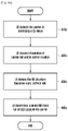
- FIG. 23 is a flowchart of a method by a terminal for transmitting or receiving at least one carrier in a cellular network according to an embodiment of the disclosure.
- the terminal receives information on frequency position of a common reference point for resource block grids from a base station at operation 2310 , and receives information on offset in frequency domain between the common reference point and a location of at least one carrier from the base station at operation 2320 .
- the information on the frequency position and the information on the offset are received in the system information or RRC signaling, simultaneously or separately.
- the information on the frequency position may represent the frequency offset in PRB between the common reference point and a lowest subcarrier of a lowest PRB of the SS block.
- the information on the frequency position may be defined in terms of resource blocks per frequency range based on whether the at least one carrier corresponds to a first frequency range or a second frequency range (e.g., sub-6 GHz, above-6 GHz, etc.)
- the information on the frequency position may represent the frequency location of the common reference point, which is expressed as in NARFCN.
- the terminal determines the location of the at least one carrier based on the information on the offset at operation 2330 .
- the terminal transmits the at least one carrier to the base station for uplink transmission, or receives the at least one carrier from the base station for downlink reception at operation 2340 .
- FIG. 24 is a flowchart of a method by a base station for transmitting or receiving at least one carrier in a cellular network according to an embodiment of the disclosure.
- the base station transmits information on frequency position of a common reference point for resource block grids to a terminal at operation 2410 , and transmits information on offset in frequency domain between the common reference point and a location of at least one carrier to the terminal at operation 2430 , in the system information or RRC signaling.
- the base station transmits the at least one carrier to the terminal for downlink transmission, or receives the at least one carrier from the terminal for uplink reception by identifying the location of the at least one carrier based on the information on the offset at operation 2430 .
- FIG. 25 is a block diagram of a terminal according to an embodiment of the disclosure.
- a terminal includes a transceiver 2510 , a controller 2520 and a memory 2530 .
- the transceiver 2510 , the controller 2520 and the memory 2530 are configured to perform UE procedures of FIGS. 2, 6 a , 6 b , 6 f , 10 , 13 a , 13 b , 18 , 22 and 23 , or described above.
- the transceiver 2510 , the controller 2520 and the memory 2530 are shown as separate entities, they may be realized as a single entity like a single chip.
- the transceiver 2510 , the controller 2520 and the memory 2530 may be electrically connected to or coupled with each other.
- the transceiver 2510 may transmit and receive signals to and from the other network entities, e.g. a base station.
- the controller 2520 may control the terminal to perform a function according to one of the embodiments described above.
- the controller 2520 may be configured to control the transceiver to receive information on frequency position of a common reference point for resource block grids from the base station, control the transceiver to receive information on offset in frequency domain between the common reference point and a location of at least one carrier from the base station, determine the location of the at least one carrier based on the information on the offset, and control the transceiver to transmit or receive the at least one carrier.
- the controller 2520 may be further configured to control the transceiver to receive a SS block from the base station.
- the controller 2520 may refer to a circuitry, an ASIC, or at least one processor.
- the operations of the terminal may be implemented using the memory 2530 storing corresponding program codes.
- the terminal may be equipped with the memory 2530 to store program codes implementing desired operations.
- the controller 2520 may read and execute the program codes stored in the memory 2530 by using a processor or a central processing unit (CPU).
- FIG. 26 is a block diagram of a base station according to an embodiment of the disclosure.
- a base station includes a transceiver 2610 , a controller 2620 and a memory 2630 .
- the transceiver 2610 , the controller 2620 and the memory 2630 are configured to perform the operations described above.
- the transceiver 2610 , the controller 2620 and the memory 2630 are shown as separate entities, they may be realized as a single entity like a single chip.
- the transceiver 2610 , the controller 2620 and the memory 2630 may be electrically connected to or coupled with each other.
- the transceiver 2610 may transmit and receive signals to and from the other network entities, e.g. a terminal.
- the controller 2620 may control the base station to perform a function according to one of the embodiments described above.
- the controller 2620 may be configured to control the transceiver to transmit information on frequency position of a common reference point for resource block grids to the terminal, control the transceiver to transmit information on offset in frequency domain between the common reference point and a location of the at least one carrier to the terminal, determine the location of the at least one carrier based on the information on the offset, and control the transceiver to transmit or receive the at least one carrier.
- the controller 2620 is further configured to control the transceiver to transmit a SS block to the terminal.
- the controller 2620 may refer to a circuitry, an ASIC, or at least one processor.
- the operations of the base station may be implemented using the memory 2630 storing corresponding program codes.
- the base station may be equipped with the memory 2630 to store program codes implementing desired operations.
- the controller 2620 may read and execute the program codes stored in the memory 2630 by using a processor or a CPU.
- the term “and/or,” when used in a list of two or more items, means that any one of the listed items can be employed by itself, or any combination of two or more of the listed items can be employed.
- the composition can contain A alone; B alone; C alone; A and B in combination; A and C in combination; B and C in combination; or A, B, and C in combination.
Landscapes
- Engineering & Computer Science (AREA)
- Signal Processing (AREA)
- Computer Networks & Wireless Communication (AREA)
- Physics & Mathematics (AREA)
- Mathematical Physics (AREA)
- Mobile Radio Communication Systems (AREA)
Priority Applications (1)
| Application Number | Priority Date | Filing Date | Title |
|---|---|---|---|
| US16/637,119 US11350397B2 (en) | 2017-08-10 | 2018-08-10 | Method and apparatus of determining frequency resources in next generation cellular networks |
Applications Claiming Priority (5)
| Application Number | Priority Date | Filing Date | Title |
|---|---|---|---|
| US201762543569P | 2017-08-10 | 2017-08-10 | |
| US201762555281P | 2017-09-07 | 2017-09-07 | |
| US201762565312P | 2017-09-29 | 2017-09-29 | |
| PCT/KR2018/009223 WO2019031937A1 (fr) | 2017-08-10 | 2018-08-10 | Procédé et appareil permettant de déterminer les ressources de fréquence dans les réseaux cellulaires de 'accès initial dans des réseaux cellulaires de la prochaine génération |
| US16/637,119 US11350397B2 (en) | 2017-08-10 | 2018-08-10 | Method and apparatus of determining frequency resources in next generation cellular networks |
Related Parent Applications (1)
| Application Number | Title | Priority Date | Filing Date |
|---|---|---|---|
| PCT/KR2018/009223 A-371-Of-International WO2019031937A1 (fr) | 2017-08-10 | 2018-08-10 | Procédé et appareil permettant de déterminer les ressources de fréquence dans les réseaux cellulaires de 'accès initial dans des réseaux cellulaires de la prochaine génération |
Related Child Applications (1)
| Application Number | Title | Priority Date | Filing Date |
|---|---|---|---|
| US17/826,571 Continuation US12177163B2 (en) | 2017-08-10 | 2022-05-27 | Method and apparatus of determining frequency resources in next generation cellular networks |
Publications (2)
| Publication Number | Publication Date |
|---|---|
| US20200252934A1 US20200252934A1 (en) | 2020-08-06 |
| US11350397B2 true US11350397B2 (en) | 2022-05-31 |
Family
ID=65271568
Family Applications (2)
| Application Number | Title | Priority Date | Filing Date |
|---|---|---|---|
| US16/637,119 Active 2038-11-04 US11350397B2 (en) | 2017-08-10 | 2018-08-10 | Method and apparatus of determining frequency resources in next generation cellular networks |
| US17/826,571 Active 2039-06-04 US12177163B2 (en) | 2017-08-10 | 2022-05-27 | Method and apparatus of determining frequency resources in next generation cellular networks |
Family Applications After (1)
| Application Number | Title | Priority Date | Filing Date |
|---|---|---|---|
| US17/826,571 Active 2039-06-04 US12177163B2 (en) | 2017-08-10 | 2022-05-27 | Method and apparatus of determining frequency resources in next generation cellular networks |
Country Status (5)
| Country | Link |
|---|---|
| US (2) | US11350397B2 (fr) |
| EP (2) | EP4236175B1 (fr) |
| KR (1) | KR102559382B1 (fr) |
| CN (2) | CN110999478B (fr) |
| WO (1) | WO2019031937A1 (fr) |
Families Citing this family (20)
| Publication number | Priority date | Publication date | Assignee | Title |
|---|---|---|---|---|
| US10575217B2 (en) * | 2017-08-11 | 2020-02-25 | Qualcomm Incorporated | Techniques and apparatuses for managing sounding reference signal (SRS) transmissions in a bandwidth part |
| CN109392157B (zh) | 2017-08-11 | 2023-01-13 | 华为技术有限公司 | 一种物理资源块prb网格的指示方法及设备 |
| CN114143885B (zh) | 2017-08-11 | 2025-10-17 | 中兴通讯股份有限公司 | 资源位置的指示、接收方法及装置 |
| CN116582941A (zh) * | 2017-08-11 | 2023-08-11 | 华为技术有限公司 | 一种资源分配的方法,终端以及网络设备 |
| JP6917480B2 (ja) * | 2017-08-11 | 2021-08-11 | 北京小米移動軟件有限公司Beijing Xiaomi Mobile Software Co.,Ltd. | クロスキャリアスケジューリング方法及び装置 |
| WO2019070101A1 (fr) * | 2017-10-02 | 2019-04-11 | 엘지전자 주식회사 | Procédé et dispositif de transmission ou de réception de données dans un système de communication sans fil |
| KR102046585B1 (ko) * | 2017-10-19 | 2019-11-19 | 엘지전자 주식회사 | 무선 통신 시스템에서 prb 그리드를 구성하는 방법 및 장치 |
| US11778657B2 (en) * | 2017-10-27 | 2023-10-03 | Apple Inc. | Control resource set information in physical broadcast channel |
| CN117715230A (zh) * | 2017-11-17 | 2024-03-15 | 华为技术有限公司 | 随机接入信号的发送方法、接收方法和相关装置 |
| US10820367B2 (en) * | 2018-02-13 | 2020-10-27 | Htc Corporation | Device and method of handling a radio resource control connection |
| US10419257B2 (en) * | 2018-02-15 | 2019-09-17 | Huawei Technologies Co., Ltd. | OFDM communication system with method for determination of subcarrier offset for OFDM symbol generation |
| JP7283908B2 (ja) * | 2019-01-24 | 2023-05-30 | シャープ株式会社 | 端末装置、基地局装置、および、通信方法 |
| EP3925345A4 (fr) | 2019-02-14 | 2022-09-14 | Nokia Technologies Oy | Configuration de ressources pour une partie de bande passante destinée à un réseau sans fil |
| EP3930393B1 (fr) * | 2019-02-22 | 2025-12-17 | Ntt Docomo, Inc. | Dispositif utilisateur et dispositif de station de base |
| WO2021079526A1 (fr) * | 2019-10-25 | 2021-04-29 | 株式会社Nttドコモ | Terminal |
| WO2021207938A1 (fr) * | 2020-04-14 | 2021-10-21 | JRD Communication (Shenzhen) Ltd. | Procédé et appareil de traitement de liaison montante |
| WO2021217322A1 (fr) * | 2020-04-27 | 2021-11-04 | Qualcomm Incorporated | Détermination du temps de préparation de transmission pour une communication sans fil sur au moins une porteuse |
| CN115486165B (zh) | 2020-04-27 | 2025-06-27 | 高通股份有限公司 | 确定用于在至少一个载波上进行无线通信的传输准备时间 |
| KR102670815B1 (ko) * | 2022-05-20 | 2024-05-30 | 주식회사 블랙핀 | 무선 이동 통신 시스템에서 기기내 공존을 위한 방법 및 장치 |
| CN121055595A (zh) * | 2024-05-29 | 2025-12-02 | 华为技术有限公司 | 无线充能方法及相关装置 |
Citations (6)
| Publication number | Priority date | Publication date | Assignee | Title |
|---|---|---|---|---|
| US20160072614A1 (en) | 2014-09-09 | 2016-03-10 | Telefonaktiebolaget L M Ericsson (Publ) | Resource Structure and Indication for Rel-13 MTC UE |
| WO2016159738A1 (fr) | 2015-04-03 | 2016-10-06 | 엘지전자 주식회사 | Procédé et dispositif d'émission et de réception d'un signal dans un système de communications sans fil |
| US20170223727A1 (en) | 2014-07-01 | 2017-08-03 | Intel Corporation | Group carrier scheduling for unlicensed long term evolution network |
| US20180368145A1 (en) * | 2017-06-15 | 2018-12-20 | Huawei Technologies Co., Ltd. | Frequency Location Indexing for a Wideband Component Carrier |
| US20190053138A1 (en) * | 2017-08-08 | 2019-02-14 | Htc Corporation | Method of Handling Measurement and Related Communication Device |
| US20190280843A1 (en) * | 2017-06-16 | 2019-09-12 | Intel IP Corporation | Physical resource block indexing for coexistence of narrow band, carrier aggregation, and wide band user equipment in new radio |
Family Cites Families (13)
| Publication number | Priority date | Publication date | Assignee | Title |
|---|---|---|---|---|
| CN102111211B (zh) * | 2009-12-26 | 2013-11-06 | 华为技术有限公司 | 物理混合重传指示信道的分配方法和设备 |
| JP5752783B2 (ja) * | 2010-03-31 | 2015-07-22 | サムスン エレクトロニクス カンパニー リミテッド | マルチ−セルtdd通信システムにおける応答信号の送信に対するリソースインデクシング |
| US9386505B2 (en) * | 2014-04-15 | 2016-07-05 | Sharp Laboratories Of America, Inc. | Systems and methods for secondary cell ID selection |
| US9847848B2 (en) | 2014-05-09 | 2017-12-19 | Samsung Electronics Co., Ltd. | Method and apparatus for performing communication by D2D communication terminal |
| KR102319182B1 (ko) * | 2014-05-09 | 2021-10-29 | 삼성전자 주식회사 | D2D(Device to Device)통신 단말의 통신 방법 및 장치 |
| KR102262300B1 (ko) * | 2015-06-17 | 2021-06-08 | 삼성전자 주식회사 | 무선 셀룰라 통신 시스템에서 협대역을 이용한 신호 전송을 위한 송수신 방법 및 장치 |
| US10285144B2 (en) * | 2015-11-05 | 2019-05-07 | Qualcomm Incorporated | Clean-slate synchronization signal design and cell search algorithms |
| CN106817194B (zh) * | 2015-12-01 | 2022-04-08 | 北京三星通信技术研究有限公司 | 参考信号发送方法、接收方法和设备 |
| EP3402251B1 (fr) * | 2016-01-07 | 2024-03-06 | Sharp Kabushiki Kaisha | Appareil terminal, procédé de communication, et circuit intégré |
| CN106961734B (zh) * | 2016-01-11 | 2023-05-30 | 中兴通讯股份有限公司 | 信息的传输方法及装置 |
| WO2018203672A1 (fr) * | 2017-05-02 | 2018-11-08 | Samsung Electronics Co., Ltd. | Procédé et appareil d'accès initial dans des réseaux cellulaires de prochaine génération |
| CN111491379B (zh) * | 2017-05-05 | 2021-05-18 | 华为技术有限公司 | 资源分配的方法、用户设备和网络设备 |
| KR102352364B1 (ko) * | 2017-06-15 | 2022-01-18 | 주식회사 아이티엘 | Nr 시스템에서 광대역 동작 방법 및 장치 |
-
2018
- 2018-08-10 EP EP23177691.5A patent/EP4236175B1/fr active Active
- 2018-08-10 US US16/637,119 patent/US11350397B2/en active Active
- 2018-08-10 WO PCT/KR2018/009223 patent/WO2019031937A1/fr not_active Ceased
- 2018-08-10 CN CN201880051830.3A patent/CN110999478B/zh active Active
- 2018-08-10 EP EP18845179.3A patent/EP3653010B1/fr active Active
- 2018-08-10 KR KR1020207007102A patent/KR102559382B1/ko active Active
- 2018-08-10 CN CN202311126143.2A patent/CN117222016A/zh active Pending
-
2022
- 2022-05-27 US US17/826,571 patent/US12177163B2/en active Active
Patent Citations (6)
| Publication number | Priority date | Publication date | Assignee | Title |
|---|---|---|---|---|
| US20170223727A1 (en) | 2014-07-01 | 2017-08-03 | Intel Corporation | Group carrier scheduling for unlicensed long term evolution network |
| US20160072614A1 (en) | 2014-09-09 | 2016-03-10 | Telefonaktiebolaget L M Ericsson (Publ) | Resource Structure and Indication for Rel-13 MTC UE |
| WO2016159738A1 (fr) | 2015-04-03 | 2016-10-06 | 엘지전자 주식회사 | Procédé et dispositif d'émission et de réception d'un signal dans un système de communications sans fil |
| US20180368145A1 (en) * | 2017-06-15 | 2018-12-20 | Huawei Technologies Co., Ltd. | Frequency Location Indexing for a Wideband Component Carrier |
| US20190280843A1 (en) * | 2017-06-16 | 2019-09-12 | Intel IP Corporation | Physical resource block indexing for coexistence of narrow band, carrier aggregation, and wide band user equipment in new radio |
| US20190053138A1 (en) * | 2017-08-08 | 2019-02-14 | Htc Corporation | Method of Handling Measurement and Related Communication Device |
Non-Patent Citations (5)
| Title |
|---|
| Ericsson, "Measurement configuration", R2-1706947, 3GPP TSG-RAN WG2 Ad Hoc, Qingdao, China, Jun. 16, 2017. |
| Huawei et al., "Overview of wider bandwidth operations", R1-1709972, 3GPP TSG RAN WG1 NR Ad Hoc Meeting, Qingdao, China, Jun. 17, 2017. |
| Indian Office Action dated Apr. 21, 2022, issued in a counterpart Indian Application No. 202037005589. |
| Mediatek Inc., "Report of email discussion [98#33][NR/Measurement configuration]", R2-1706570, 3GPP TSG-RAN WG2 NR#2, Qingdao, China, Jun. 16, 2017. |
| Nokia et al., "On wider band aspects of NR", R1-1710883, 3GPP TSG-RAN WG1 Meeting NR#2, Qingdao, China, Jun. 16, 2017. |
Also Published As
| Publication number | Publication date |
|---|---|
| CN110999478A (zh) | 2020-04-10 |
| KR102559382B1 (ko) | 2023-07-25 |
| US20200252934A1 (en) | 2020-08-06 |
| EP3653010B1 (fr) | 2023-06-07 |
| EP3653010A1 (fr) | 2020-05-20 |
| KR20200031176A (ko) | 2020-03-23 |
| EP4236175A3 (fr) | 2023-10-25 |
| US12177163B2 (en) | 2024-12-24 |
| CN110999478B (zh) | 2023-09-19 |
| WO2019031937A1 (fr) | 2019-02-14 |
| EP4236175B1 (fr) | 2026-05-06 |
| US20220312394A1 (en) | 2022-09-29 |
| CN117222016A (zh) | 2023-12-12 |
| EP4236175A2 (fr) | 2023-08-30 |
| EP3653010A4 (fr) | 2021-04-07 |
Similar Documents
| Publication | Publication Date | Title |
|---|---|---|
| US12177163B2 (en) | Method and apparatus of determining frequency resources in next generation cellular networks | |
| US12192932B2 (en) | Method and apparatus of initial access in next generation cellular networks | |
| US20250151054A1 (en) | Method for transmitting and receiving shared channel in wireless communication system, and device supporting same | |
| US11683768B2 (en) | Method and apparatus for time and frequency tracking in cellular communication system | |
| US11246124B2 (en) | Method and apparatus for downlink control information design for network coordination | |
| US11553471B2 (en) | Method and apparatus for transmitting data | |
| CN116743321B (zh) | 无线通信系统中的下行数据接收和harq-ack传输的方法、装置和系统 | |
| US11283663B2 (en) | Method and device for transmitting/receiving synchronization signal in wireless cellular communication system | |
| US10715373B2 (en) | Method and device for transmitting/receiving synchronization signal in wireless cellular communication system | |
| US10880146B2 (en) | Method and device for transmitting/receiving synchronization signal in wireless cellular communication system | |
| US11303391B2 (en) | Method and apparatus for transmitting uplink channels in wireless communication system | |
| CN110268648B (zh) | 无线蜂窝通信系统中执行随机接入的方法和设备 | |
| US20200120645A1 (en) | Control channel transmitting and receiving method and apparatus in wireless communication system |
Legal Events
| Date | Code | Title | Description |
|---|---|---|---|
| AS | Assignment |
Owner name: SAMSUNG ELECTRONICS CO., LTD., KOREA, REPUBLIC OF Free format text: ASSIGNMENT OF ASSIGNORS INTEREST;ASSIGNORS:XUE, PENG;YUN, YEOHUN;RYU, HYUNSEOK;AND OTHERS;SIGNING DATES FROM 20191220 TO 20200206;REEL/FRAME:051742/0688 |
|
| FEPP | Fee payment procedure |
Free format text: ENTITY STATUS SET TO UNDISCOUNTED (ORIGINAL EVENT CODE: BIG.); ENTITY STATUS OF PATENT OWNER: LARGE ENTITY |
|
| STPP | Information on status: patent application and granting procedure in general |
Free format text: DOCKETED NEW CASE - READY FOR EXAMINATION |
|
| STPP | Information on status: patent application and granting procedure in general |
Free format text: NON FINAL ACTION MAILED |
|
| STPP | Information on status: patent application and granting procedure in general |
Free format text: RESPONSE TO NON-FINAL OFFICE ACTION ENTERED AND FORWARDED TO EXAMINER |
|
| STPP | Information on status: patent application and granting procedure in general |
Free format text: FINAL REJECTION MAILED |
|
| STPP | Information on status: patent application and granting procedure in general |
Free format text: RESPONSE AFTER FINAL ACTION FORWARDED TO EXAMINER |
|
| STPP | Information on status: patent application and granting procedure in general |
Free format text: NOTICE OF ALLOWANCE MAILED -- APPLICATION RECEIVED IN OFFICE OF PUBLICATIONS |
|
| STPP | Information on status: patent application and granting procedure in general |
Free format text: PUBLICATIONS -- ISSUE FEE PAYMENT VERIFIED |
|
| STCF | Information on status: patent grant |
Free format text: PATENTED CASE |
|
| MAFP | Maintenance fee payment |
Free format text: PAYMENT OF MAINTENANCE FEE, 4TH YEAR, LARGE ENTITY (ORIGINAL EVENT CODE: M1551); ENTITY STATUS OF PATENT OWNER: LARGE ENTITY Year of fee payment: 4 |