US11369939B2 - Contacter - Google Patents
Contacter Download PDFInfo
- Publication number
- US11369939B2 US11369939B2 US16/087,254 US201716087254A US11369939B2 US 11369939 B2 US11369939 B2 US 11369939B2 US 201716087254 A US201716087254 A US 201716087254A US 11369939 B2 US11369939 B2 US 11369939B2
- Authority
- US
- United States
- Prior art keywords
- fluid
- ledges
- flow
- contactor
- gas scrubber
- Prior art date
- Legal status (The legal status is an assumption and is not a legal conclusion. Google has not performed a legal analysis and makes no representation as to the accuracy of the status listed.)
- Active, expires
Links
Images


Classifications
-
- B—PERFORMING OPERATIONS; TRANSPORTING
- B01—PHYSICAL OR CHEMICAL PROCESSES OR APPARATUS IN GENERAL
- B01J—CHEMICAL OR PHYSICAL PROCESSES, e.g. CATALYSIS OR COLLOID CHEMISTRY; THEIR RELEVANT APPARATUS
- B01J19/00—Chemical, physical or physico-chemical processes in general; Their relevant apparatus
-
- B—PERFORMING OPERATIONS; TRANSPORTING
- B01—PHYSICAL OR CHEMICAL PROCESSES OR APPARATUS IN GENERAL
- B01J—CHEMICAL OR PHYSICAL PROCESSES, e.g. CATALYSIS OR COLLOID CHEMISTRY; THEIR RELEVANT APPARATUS
- B01J19/00—Chemical, physical or physico-chemical processes in general; Their relevant apparatus
- B01J19/32—Packing elements in the form of grids or built-up elements for forming a unit or module inside the apparatus for mass or heat transfer
-
- B—PERFORMING OPERATIONS; TRANSPORTING
- B01—PHYSICAL OR CHEMICAL PROCESSES OR APPARATUS IN GENERAL
- B01D—SEPARATION
- B01D3/00—Distillation or related exchange processes in which liquids are contacted with gaseous media, e.g. stripping
-
- B—PERFORMING OPERATIONS; TRANSPORTING
- B01—PHYSICAL OR CHEMICAL PROCESSES OR APPARATUS IN GENERAL
- B01D—SEPARATION
- B01D3/00—Distillation or related exchange processes in which liquids are contacted with gaseous media, e.g. stripping
- B01D3/14—Fractional distillation or use of a fractionation or rectification column
- B01D3/26—Fractionating columns in which vapour and liquid flow past each other, or in which the fluid is sprayed into the vapour, or in which a two-phase mixture is passed in one direction
- B01D3/28—Fractionating columns with surface contact and vertical guides, e.g. film action
-
- B—PERFORMING OPERATIONS; TRANSPORTING
- B01—PHYSICAL OR CHEMICAL PROCESSES OR APPARATUS IN GENERAL
- B01J—CHEMICAL OR PHYSICAL PROCESSES, e.g. CATALYSIS OR COLLOID CHEMISTRY; THEIR RELEVANT APPARATUS
- B01J2219/00—Chemical, physical or physico-chemical processes in general; Their relevant apparatus
- B01J2219/32—Details relating to packing elements in the form of grids or built-up elements for forming a unit of module inside the apparatus for mass or heat transfer
- B01J2219/322—Basic shape of the elements
- B01J2219/32203—Sheets
- B01J2219/32206—Flat sheets
-
- B—PERFORMING OPERATIONS; TRANSPORTING
- B01—PHYSICAL OR CHEMICAL PROCESSES OR APPARATUS IN GENERAL
- B01J—CHEMICAL OR PHYSICAL PROCESSES, e.g. CATALYSIS OR COLLOID CHEMISTRY; THEIR RELEVANT APPARATUS
- B01J2219/00—Chemical, physical or physico-chemical processes in general; Their relevant apparatus
- B01J2219/32—Details relating to packing elements in the form of grids or built-up elements for forming a unit of module inside the apparatus for mass or heat transfer
- B01J2219/322—Basic shape of the elements
- B01J2219/32203—Sheets
- B01J2219/32224—Sheets characterised by the orientation of the sheet
- B01J2219/32227—Vertical orientation
-
- B—PERFORMING OPERATIONS; TRANSPORTING
- B01—PHYSICAL OR CHEMICAL PROCESSES OR APPARATUS IN GENERAL
- B01J—CHEMICAL OR PHYSICAL PROCESSES, e.g. CATALYSIS OR COLLOID CHEMISTRY; THEIR RELEVANT APPARATUS
- B01J2219/00—Chemical, physical or physico-chemical processes in general; Their relevant apparatus
- B01J2219/32—Details relating to packing elements in the form of grids or built-up elements for forming a unit of module inside the apparatus for mass or heat transfer
- B01J2219/322—Basic shape of the elements
- B01J2219/32286—Grids or lattices
-
- B—PERFORMING OPERATIONS; TRANSPORTING
- B01—PHYSICAL OR CHEMICAL PROCESSES OR APPARATUS IN GENERAL
- B01J—CHEMICAL OR PHYSICAL PROCESSES, e.g. CATALYSIS OR COLLOID CHEMISTRY; THEIR RELEVANT APPARATUS
- B01J2219/00—Chemical, physical or physico-chemical processes in general; Their relevant apparatus
- B01J2219/32—Details relating to packing elements in the form of grids or built-up elements for forming a unit of module inside the apparatus for mass or heat transfer
- B01J2219/322—Basic shape of the elements
- B01J2219/32296—Honeycombs
-
- B—PERFORMING OPERATIONS; TRANSPORTING
- B01—PHYSICAL OR CHEMICAL PROCESSES OR APPARATUS IN GENERAL
- B01J—CHEMICAL OR PHYSICAL PROCESSES, e.g. CATALYSIS OR COLLOID CHEMISTRY; THEIR RELEVANT APPARATUS
- B01J2219/00—Chemical, physical or physico-chemical processes in general; Their relevant apparatus
- B01J2219/32—Details relating to packing elements in the form of grids or built-up elements for forming a unit of module inside the apparatus for mass or heat transfer
- B01J2219/324—Composition or microstructure of the elements
- B01J2219/32408—Metal
-
- B—PERFORMING OPERATIONS; TRANSPORTING
- B01—PHYSICAL OR CHEMICAL PROCESSES OR APPARATUS IN GENERAL
- B01J—CHEMICAL OR PHYSICAL PROCESSES, e.g. CATALYSIS OR COLLOID CHEMISTRY; THEIR RELEVANT APPARATUS
- B01J2219/00—Chemical, physical or physico-chemical processes in general; Their relevant apparatus
- B01J2219/32—Details relating to packing elements in the form of grids or built-up elements for forming a unit of module inside the apparatus for mass or heat transfer
- B01J2219/324—Composition or microstructure of the elements
- B01J2219/32425—Ceramic
-
- B—PERFORMING OPERATIONS; TRANSPORTING
- B01—PHYSICAL OR CHEMICAL PROCESSES OR APPARATUS IN GENERAL
- B01J—CHEMICAL OR PHYSICAL PROCESSES, e.g. CATALYSIS OR COLLOID CHEMISTRY; THEIR RELEVANT APPARATUS
- B01J2219/00—Chemical, physical or physico-chemical processes in general; Their relevant apparatus
- B01J2219/32—Details relating to packing elements in the form of grids or built-up elements for forming a unit of module inside the apparatus for mass or heat transfer
- B01J2219/324—Composition or microstructure of the elements
- B01J2219/32441—Glass
-
- B—PERFORMING OPERATIONS; TRANSPORTING
- B01—PHYSICAL OR CHEMICAL PROCESSES OR APPARATUS IN GENERAL
- B01J—CHEMICAL OR PHYSICAL PROCESSES, e.g. CATALYSIS OR COLLOID CHEMISTRY; THEIR RELEVANT APPARATUS
- B01J2219/00—Chemical, physical or physico-chemical processes in general; Their relevant apparatus
- B01J2219/32—Details relating to packing elements in the form of grids or built-up elements for forming a unit of module inside the apparatus for mass or heat transfer
- B01J2219/324—Composition or microstructure of the elements
- B01J2219/32466—Composition or microstructure of the elements comprising catalytically active material
-
- B—PERFORMING OPERATIONS; TRANSPORTING
- B01—PHYSICAL OR CHEMICAL PROCESSES OR APPARATUS IN GENERAL
- B01J—CHEMICAL OR PHYSICAL PROCESSES, e.g. CATALYSIS OR COLLOID CHEMISTRY; THEIR RELEVANT APPARATUS
- B01J2219/00—Chemical, physical or physico-chemical processes in general; Their relevant apparatus
- B01J2219/32—Details relating to packing elements in the form of grids or built-up elements for forming a unit of module inside the apparatus for mass or heat transfer
- B01J2219/324—Composition or microstructure of the elements
- B01J2219/32483—Plastics
-
- B—PERFORMING OPERATIONS; TRANSPORTING
- B01—PHYSICAL OR CHEMICAL PROCESSES OR APPARATUS IN GENERAL
- B01J—CHEMICAL OR PHYSICAL PROCESSES, e.g. CATALYSIS OR COLLOID CHEMISTRY; THEIR RELEVANT APPARATUS
- B01J2219/00—Chemical, physical or physico-chemical processes in general; Their relevant apparatus
- B01J2219/32—Details relating to packing elements in the form of grids or built-up elements for forming a unit of module inside the apparatus for mass or heat transfer
- B01J2219/324—Composition or microstructure of the elements
- B01J2219/32491—Woven or knitted materials
-
- B—PERFORMING OPERATIONS; TRANSPORTING
- B01—PHYSICAL OR CHEMICAL PROCESSES OR APPARATUS IN GENERAL
- B01J—CHEMICAL OR PHYSICAL PROCESSES, e.g. CATALYSIS OR COLLOID CHEMISTRY; THEIR RELEVANT APPARATUS
- B01J2219/00—Chemical, physical or physico-chemical processes in general; Their relevant apparatus
- B01J2219/32—Details relating to packing elements in the form of grids or built-up elements for forming a unit of module inside the apparatus for mass or heat transfer
- B01J2219/332—Details relating to the flow of the phases
- B01J2219/3322—Co-current flow
-
- B—PERFORMING OPERATIONS; TRANSPORTING
- B01—PHYSICAL OR CHEMICAL PROCESSES OR APPARATUS IN GENERAL
- B01J—CHEMICAL OR PHYSICAL PROCESSES, e.g. CATALYSIS OR COLLOID CHEMISTRY; THEIR RELEVANT APPARATUS
- B01J2219/00—Chemical, physical or physico-chemical processes in general; Their relevant apparatus
- B01J2219/32—Details relating to packing elements in the form of grids or built-up elements for forming a unit of module inside the apparatus for mass or heat transfer
- B01J2219/332—Details relating to the flow of the phases
- B01J2219/3325—Counter-current flow
Definitions
- the invention relates to a device, in particular a contactor for bringing into contact at least two fluid flows, comprising a structure for conducting a first fluid, whereby the structure has in addition an interface, which interface is arranged to conduct a second fluid whereby in the contact zone the first fluid can be brought into contact with the second fluid.
- the invention also relates to an arrangement comprising at least a device as well as a method for producing a contact between a first and a second fluid.
- the fluid flows may consist of two immiscible fluids or a gaseous fluid and a liquid.
- different techniques are applied.
- one fluid flow may be dispersed or atomized in the respective other flow in order to produce a large surface between the fluids.
- the two fluids are separated again in a later step.
- the two fluids can be passed through a receptacle concurrently, in the inside of which large surfaces for contacting the fluid flows are provided. Examples for such devices are tower-packing columns or columns with structured packing.
- cross-current contactors can be used as well.
- cross-current contactors the two fluid flows do not run in the same direction, as is the case with concurrent, nor in opposite directions, as is the case with counter-current, but rather cross each other and exchange materials while crossing.
- Examples are cross-current film evaporators or gas scrubbers, in which a fluid flows downwardly on the surface of packings or structured internals due to gravity as a film, while a vapor or gas flow passes the structures in a direction deviating from the flow direction of the fluid and is brought into contact with said film.
- distillation One type of such fluid-fluid contacting processes is distillation.
- a material exchange is typically generated between a fluid and a gas flow concurrently.
- distillation in structured packaging it turned out that typically, there is a natural limit in case of a drop in pressure of the gas fluid of approximately 10-12 mbar/m. Process points with a larger drop in pressure in the upturned gas flow are therefore often impossible, as usually the column would be flooded.
- the currently known contactors have the disadvantage that due to their tendency to flood they allow only a limited mass transfer.
- the objective of the invention is to provide a device that is associated with the initially described technical field, with which two fluids are brought into contact, whereby a risk of flooding or the risk of having one fluid dragged away are reduced. This in particular in such a manner that an intensive material exchange between the fluids to be processed can be achieved in case of very high flow rates of the two fluids, and that the device for the material exchange can be built more compactly.
- At least one flow breaker is arranged in the contact zone for interrupting a flow of the second fluid.
- the device is used with that in order to produce a contact between a first fluid and a second fluid in a process.
- the flow velocity of the second fluid is selected such that no flooding occurs.
- the formation of the flow breaker in the contact zone of the structure among other things has the effect, among other things, that the flooding phenomenon in case of counter-current, or, respectively, the dragging away of the fluid in the film in case of cross-current can be prevented.
- the first fluid is conducted in the structure for conducting the first fluid, especially in pores and/or capillaries of the structure, so that it wets the structure for conducting the first fluid.
- the second fluid flows along the contact zone, in particular through the areas of the device that are located outside the structure for conducting the first fluid and do particularly not comprise any pores and/or capillaries of the structure, so that it does hardly wet the structure for conducting the first fluid or does not wet it at all.
- a particularly efficient device for contacting a first fluid with a second fluid in a manner without dispersing the first fluid in the second fluid or vice versa In this manner, a particularly intensive contact between the first fluid and the second fluid at the interface is achieved.
- the flow velocity can be selected so that a risk of flooding is only reduced.
- the structure can principally be chosen arbitrarily. The only requirement regarding the structure is that a fluid can be conducted from a first end of the structure to a second end of the structure. The first fluid need not be conducted straight, but can also be conducted along a random path through the structure.
- the contact zone is in particular an area of a surface, an enveloping surface and/or a boundary surface of the structure for conducting the first fluid.
- the contact zone is essentially defined by the geometry of the structure for conducting the first fluid, in particular by the geometry of the outer boundary and/or an enveloping surface of the structure for conducting the first fluid.
- the contact zone is situated in particular outside the structure for conducting the first fluid and does particularly not comprise any pores and/or capillaries.
- the contact zone is designed in such a way that the first fluid flowing inside the structure for conducting the first fluid can get into contact with the second fluid in the contact zone, which second fluid flows outside the structure for conducting the first fluid.
- an interface forms in the contact zone between the first fluid and the second fluid.
- this is a phase separation surface between the two fluids.
- the interface is thus not automatically understood as geometrically distinct surface at the structure for conducting the first fluid.
- the interface is in particular not necessarily identical with the surface, the enveloping surface and/or the boundary surface of the structure for conducting the first fluid.
- the interface between the fluids may vary and be located, for instance, above the surface, the enveloping surface and/or the boundary surface of the structure for conducting the first fluid.
- the form and position of the interface particularly depends on the fluids used, the flow condition and/or the pressure distributions in the flows of the two fluids.
- the interface is specifically a curved and/or bulbous surface, which is particularly interrupted and/or limited by the at least one flow breaker.
- the first fluid and/or the second fluid may be present as any flowing substance, especially as liquid, vapor, aerosol, foam, etc. This is subject to the precondition that the two fluids cannot be homogenously mixed with each other.
- a “homogenous mixture” in the present context defines a mixture of two fluids that are mixed on a molecular level and are in a phase, i.e. they are optically not recognizable as mixture.
- the first fluid is preferably a liquid, in particular when using the device in an extraction. Especially with respect to distillation or gas scrubbing the first fluid may also be a gas.
- the second fluid is preferably present as a gas. In some variants, it might as well be a liquid. However, the first and the second fluids are not simultaneously present as a gas.
- the flow breaker is preferably an element that can impact the flow of the second fluid.
- the term “interrupting a flow” is generally understood as changing the flow behavior. Such change may include the deceleration of the flow velocity, redirecting the fluid flow or the like.
- references including the term “and/or” principally have to be interpreted in such a manner that a non-null subset of the listed features can be selected.
- the device can also be operated in such a manner that eddying does not occur. Instead, the device can be operated as such, for instance, that there is only a deceleration of the second fluid.
- the structure, the contact zone and/or the boundary surface are preferably arranged in such a manner that a good blending is achieved in the respective fluids. With that it can be achieved that in the contact areas fresh fluid is always available.
- the flow breaker preferably comprises at least two ledges, whereby the second fluid can in particular flow in a second direction, which crosses the direction of the ledges.
- the term ledge is essentially understood as a prismatic element. Preferably, it is a rectangular block shape, especially an elongated block shape.
- the ledges can be formed integrally with the structure, but the device can also consist of ledges and structures in some variants.
- the ledge can be formed prismatically with a non-rectangular cross section.
- the flow breaker can also be formed differently.
- the flow breaker may, for instance, be wave line shaped, zig-zag shaped, meandering or in any other similar shape. The skilled person knows about further possible arrangements of a flow breaker.
- the flooding phenomenon in cross-current, or the dragging away in the cross-current, respectively, is thus preferably prevented by a ledge system that is arranged along the boundary surface between the two flow directions of the first fluid and the second fluid.
- the ledges are preferably approximately perpendicular relative to the moving direction of the second fluid, which does preferably not substantially wet the structure.
- the ledges form an angle in the range of 70° to 90° with the flow direction of the second fluid. In special embodiments, the angle may even be smaller than 70°.
- the ratio of the distance between two neighboring ledges and the height of the ledges is preferably in a range of 1 to 10, particularly preferred in a range of 3 to 7. This means that the distance between two neighboring ledges is preferably 1 to 10 times larger, particularly preferred 3 to 7 times larger than the height of the ledges as such. In tests it was able to prove that in case of insufficient distances between two neighboring ledges typically the contact between the first fluid and the second fluid cannot be sufficiently ensured. On the other hand, in case of too great distances, the effect of the ledges as flow breakers may be too insignificant, which would rather cause flooding again.
- the aforementioned range of a factor between 1 and 10 and particularly preferred between 3 and 7 also depends on the used fluids as well as the size of the device as such, the flow directions, the volume flows, etc. The skilled person thus understands that the factor might as well be more than 10 or less than 1.
- the flow between the ledges can be specifically adjusted by using a suitable height of the ledges as well as a suitable distance between the neighboring ledges. Surprisingly, it turned out in numerous experiments that by choosing the suitable dimensions, in particular the ratio between height of and distances between the ledges the material exchange between the first fluid and the second fluid can be increased, although the velocity between the phases at the boundary surface is typically reduced.
- the structure is constructed and the flow breakers are arranged in such a manner that the first fluid can flow in a first direction, which crosses the flow breaker.
- the first fluid does particularly not flow in a direction parallel to the direction of the flow breaker or the direction of the ledges, respectively.
- a good contacting of the second fluid can be achieved with the first fluid, as in this way the first fluid is not conducted partially behind the flow breaker or the ledges, respectively.
- the structure may be such that the first fluid conducted parallel to the ledges is not conducted behind the ledges. This can be achieved by using suitable channels, capillaries and the like.
- a cross-current may be provided, whereby the first fluid is conducted relative to the ledges in a right angle, and the second fluid is conducted parallel to the ledges.
- the ledges may be arranged horizontally, for instance.
- the ledges can be arranged approximately vertically, as the second fluid, which hardly wets the structure or does not wet the structure at all, typically flows approximately horizontally in cross current.
- the velocity between the phases at the contact surface can be significantly reduced, which largely avoids a dragging away of the fluid.
- the ledges can be dimensioned in such a manner that defined vortexes form between them. With that, the flow velocity of the second fluid can be reduced, or the flow direction can be turned to another direction. For ledges which are perpendicular to the flow direction of the second fluid, under some circumstances the flow direction can even be completely turned around by the vortex along the contact surface. In case of a counter-current contactor, exactly where the two phases are in direct contact, locally a concurrent contactor can be formed. This is particularly advantageous, as there is typically no flooding in case of a concurrent contactor.
- the first direction forms an angle of 60° to 90° with the ledge direction, in particular an angle of 75° to 90°, preferably an angle of 80° to 90°. This allows a particularly optimized contacting of the two fluids.
- the angle can also be in a different range, in particular below 60°.
- the structure is wetted by the first fluid, while in particular the second fluid does not wet the surface of the structure at all or only to a lesser extent.
- the throughput of the two fluids can also be adjusted by concretely selecting the structure, for instance based on the pore size of the structure, depending on the viscosity of the fluid.
- a ledge, a collar and/or a structuring of the surface may be provided.
- Conducting the fluids through the structure and the contact zone can furthermore be controlled by choosing the wettability of the ledges.
- the ledge comprises a region proximal to the structure, which has a first wettability, as well as a region distal to the structure, which has a second wettability differing from the first wettability.
- the structure may be made of a hydrophilic material, in particular hydrophilic ceramics, such as aluminum oxide, zirconium oxide and/or titanium oxide, and can thus be very well wettable for polar substances.
- the ledges may also be made of a hydrophilic material, in particular a hydrophilic ceramic, e.g. aluminum oxide, zirconium oxide and/or titan oxide, and on the outside, they can be made of a more hydrophobic material, in particular a ceramic material containing rare earths. Particularly suitable as more hydrophobic material is, for instance, cerium dioxide. The skilled person knows further suitable materials or coatings.
- a hydrophilic ceramic is particularly understood as ceramic material, which—in relation to water—has a contact angle of ⁇ 10°. Contact angles of >85° are regarded as hydrophobic.
- a ledge, a collar and/or a surface structuring may be provided instead of or in addition to the selection of the wettability of the regions of the ledges.
- the structure comprises one or several of the following features:
- open-pored material in particular a foam
- the structure may comprise a stepped structure, an open-pored material or a foam, etc.
- the stepped structure proved as particularly advantageous in practice.
- the structure may also comprise other or additional features.
- a mean diameter of capillaries, of free spaces in the staged structure and/or of the pores is preferably in a range of 50 micro meters to 5 millimeters, in particular of 100 micrometers to 2 millimeters, especially 200 micrometers to 1 millimeter. The diameter is thereby measured specifically perpendicular to a longitudinal direction of the respective structure.
- the ledges are easily wettable by the first fluid, preferably on the side of the capillaries of the structure, and preferably they are wetted in operation. This helps balancing out the pressure difference by capillary forces.
- the ledges are advantageously arranged in a manner that they cannot be wetted by the first fluid or that wetting is very difficult. This can be achieved, for instance, by providing a suitable surface structure on the surface of the ledges in this area, in that the surfaces of the ledges can be suitably coated in this area, or in that the ledges in this area are made of a material that is difficult to be wetted by the first fluid. Due to the typically small dimensions of the structures described herein and the also typically complex three-dimensional structure, this material selection turned out to be particularly advantageous for the ledges.
- the first fluid does not flow parallel to the ledges, it must be possible that it flows underneath the ledges.
- Capillaries could be formed, for instance, which are directed underneath the ledges.
- the capillaries can advantageously be dimensioned in a way that the pressure differences between the area before a ledge and the area behind a ledge can be balanced out by the capillary forces.
- the capillaries should not be dimensioned too small, as the fluid velocity may become too slow in very small capillaries because of the friction.
- the capillaries therefore preferably have to be adjusted to the two fluids as well as the further process parameters of the device, such as the temperature, flow velocity, volume flow, etc.
- the capillary structure conducting the liquid may be provided as a row of levels arranged in parallel to each other that are connected to one another through bars. However, it may also be provided monolithically as honeycomb body with different comb shapes (triangle, rectangle, square, hexagon).
- the ledges can either be aligned precisely vertically to the flow direction of the second fluid. Specifically, in the version with a body consisting of several planes arranged parallel to one another, the ledges could also be arranged at a small angle relative to the vertical to the flow direction of the second fluid. With that, a circulation move is induced in the flow of the second fluid, which effects an additional blending of the second fluid.
- the capillaries, in which the first fluid flows may advantageously be realized by crossing step bars as described in the application EP2897783. In this way it can be ensured that the liquid is intensively blended in the capillaries of the structure during the material exchange and thus the material exchange is intensified.
- the capillaries can also be arranged at random, and, for instance, be made of open-pored foam structures that are commercially available made of plastic materials, metals or ceramics.
- the structure is built in honeycomb shape, whereby the flow breakers protrude inwardly in the honeycombs.
- several devices comprise a joint boundary surface in combination, which form a polygonal channel for conducting the second fluid.
- the honeycomb structure is simply designed and can thus be manufactured cost-effectively.
- any other shape of the structure can be provided (see below).
- the honeycombs have a cross-section that is shaped as a regular polygon, in particular a triangle, a rectangle or a hexagon.
- a regular polygon in particular a triangle, a rectangle or a hexagon.
- the structure comprises step bar elements.
- step bar elements is particularly preferred in a layer-by-layer construction of the structure, as in this manner a layer for a tread can be formed.
- the stepped structure has the advantage that the first fluid is mixed in itself when overflowing.
- the structure may also comprise smooth ramps instead of the step bar elements.
- the structure preferably comprises several step bar elements that are arranged cross-wise. In this manner it is achieved that the first fluid has to pass through a large number of directional changes in the structure, which, in turn, would improve the blending.
- cross-wisely arranged smooth ramps may be provided in a variant.
- the capillaries could also be arranged at random, and may be made of open-pored foam structures, for instance, consisting of plastic material, metals or ceramics.
- Other assemblies of the capillary structure could also be imagined, for instance by means of tissue or other porous materials.
- An arrangement preferably comprises a device comprising a structure and a flow breaker, whereby at a first end of the device a distributor for distributing the first fluid is arranged in the structure, and a collector for collecting the first fluid from the structure is arranged at the other end located opposite said first end.
- the distributor and the collector may comprise one or several supply or discharge lines each for the first fluid. However, it is particularly preferred that the distributor and the collector have exactly one supply or discharge line each.
- a distributor and/or collector may also be foregone.
- the structure could be impinged at the first end directly with the first fluid, for instance.
- Several devices could also be connected with each other in such a way that the first fluid is conducted through structures of the several devices (see below), and wherein a device of a first end comprises a distributor, and a device of the second end comprises a collector.
- the collector and the distributor do not necessarily have to be opposite one another regarding the flow direction of the first fluid.
- the distributor and the collector could as well be integral parts of the device and connected with the device in one piece.
- a distributor for distributing the first fluid, in particular distributing a liquid, in the structure is provided at the upper end of the structure that is preferably adjusted to said structure. At the opposite end of the structure there is preferably at least one corresponding liquid collector.
- Said distributor in particular a liquid distributor, for instance, and the collector, in particular the liquid collector, for instance, could be generated with the same production method mentioned above for a layer-by-layer assembly of structures, with which the device can be produced as well.
- the distributor and the collector can also be produced fixed with the structure of the contactor, in particular built or produced integrally.
- two devices are arranged in such a manner that the first end of the first device is connected to a second end of the second device in such a manner that the first fluid can be conducted from the structure of the first device to the structure of the second device.
- Several such arrangements can be connected in parallel and/or in series, which increases the performance of the contactor. In this manner, several such devices can be put together like modules to form contactors of any size.
- these devices could, for instance, be arranged only in parallel.
- a method for producing a device described above comprises an assembly by means of an additive process. With that, the devices can be assembled particularly easily.
- the assembly is preferably taking place directly through data models by means of a chemical or physical process.
- the skilled person is familiar with a plurality of methods.
- the assembly of the device is preferably in layers, which are continuously applied on top of each other. In this manner the device can be produced cost-efficiently in big quantities. Furthermore, this helps to achieve different geometries of the structure and the ledges very easily. Such methods are also known as 3D printing methods and can principally be implemented with almost every material.
- the ledge heights could be in a range of 50 to some 100 micrometers, for instance.
- the dimensions of the capillaries are typically predetermined by the desired liquid throughput and the viscosity of the liquid. They can vary in the range of some 100 micrometers up to several millimeters.
- structured counter-current contactors can be realized with specific contact surfaces of more than 1000 m 2 /m 3 .
- the layer-by-layer assembly can also be renounced.
- Single elements of the device could be produced instead and connected with each other in another procedural step. The skilled person knows further variants in this context.
- the layer could be cured, for instance.
- a cured layer can build a compound with an already existing layer that under some circumstances may be already hardened.
- the bonding process could also be skipped.
- a bonding process could also be provided each time after applying more than one layer.
- a layer is preferably applied by means of a stencil.
- the stencil may be designed in such a manner that it can be positioned as even plane over a printing plate. Recesses in the stencil typically define the shape of the layer.
- a stencil or a shaping tool may define a plurality of identical or different shapes for layers. Stencils can particularly also be used for the same layers, which only differ in their position within the plane (turned, rotated, mirrored). With this process layers can be built up quickly and automatically. The process is thus particularly suitable for the mass production of devices.
- the shaping tool is a screen, in particular a screen for technical screen printing.
- a stencil can be renounced as well.
- the intermediate spaces could be filled with a removable fill material.
- the filling of the intermediate spaces could be renounced as well.
- the stencil is preferably used to form a plastically deformable mass to provide a layer.
- suspensions These can comprise fine-grained power as main substance. Suitable to this end are, among other things, metals, metal alloys as well as ceramics and glass ceramics.
- organic binders can be added, for example CMC (carboxy methyl cellulose), polyolefin, starch (cornmeal, wheat flour, etc.).
- CMC carboxy methyl cellulose
- polyolefin polyolefin
- starch cornmeal, wheat flour, etc.
- photopolymers can be used as organic binders. There is a large number of different photopolymers.
- acryl monomers among others hexane-1.6-diol-diacrylat, trimethyl propane triacrylate, poly (ethylene glycol) diacrylate that were blended with small amounts of photoinitiators, such as 0.5% 2.2-dimethoxy-2-phenyl acetophenone, can be considered as possible binders.
- these monomers can be blended with different oligomers of polyacrylates.
- the plastically deformable mass is intended for sintering, which is the case, for instance, with respect to ceramics, metals or glass, it preferably contains a particularly high share of the powder to be sintered, in particular >35 percent by volume, more precisely in particular >50 percent by volume.
- the plastically deformable masses comprise additional additives that can be used for changing the rheologic properties of the mass, for instance dispersing aids.
- additional additives that can be used for changing the rheologic properties of the mass, for instance dispersing aids.
- Such additives are known to the skilled person and can be selected individually to fit the required preconditions (Journal of Engineering, Volume 2013 (2013), Article ID 930832).
- the plastically deformable mass comprises pure plastic parts. These can comprise the corresponding monomers and/or oligomers that are polymerized later. Such plastically deformable masses can also comprise additional additives for setting the rheologic properties as well as solvents, pigments, catalysts or biocides.
- the plastically deformable mass may contain powder of a base material as a suspension from a group consisting of: metals, metal alloys, ceramics, metal-ceramic composites, glass, plastic materials and/or plastic composites with reinforced fibers or metal or ceramic particles. Blends of these materials are imaginable as well.
- a flow breaker is applied to a structure. It is particularly preferred that the flow breaker comprises several applied layers. The flow breaker may thereby be applied either separately or integrally with the structure. In preferred proceedings the flow breaker may be applied with different materials which differ with respect to the wettability. In this way, a first region of the strut having a first wettability and facing the structure may receive a first material in one or several layers, whereas one or more of the following layers applied may consist of a second material, which has a second wettability that differs from the first one.
- the structure alone may be built up layer by layer, while the flow breakers are subsequently connected to the structure.
- the device is preferably solidified by a bonding process, in particular by heating or sintering.
- a sinter material from the group specified above is used as plastically deformable mass, such as metals, metal alloys, ceramics, glass or composites of these materials
- the process according to the invention particularly preferably comprises a thermal treatment of the applied layers for sintering, which is carried out after the completion of the shaping process of the layers applied.
- the contactor is sintered at temperatures ranging from 500 to 2,500° C., preferably at 600 to 1,700° C.
- the solidification process can be skipped, provided that the used material allows that.
- the solidification process can also take place by means of triggering a polymerization or the like. The skilled person is familiar with further techniques in this respect.
- the process for producing the device is preferably a process in accordance with the international patent application no. PCT/CH2014/000177.
- the device is preferably provided in a manner that it can be cleaned. It is particularly preferred to produce the device from a ceramic so that the device can be cleaned by heating, in particular by burnout.
- the device may also be intended for the single use, in particular if the device is exposed to chemicals in operation, or if residues occur that cannot be removed.
- a device or arrangement is achieved, in which the material exchange process can be carried out with much smaller volumes.
- the structural volume is highly significant and expensive, so that the device or arrangement described herein is particularly preferred in FLNG platforms.
- cost-efficient plants can be realized in general.
- the presented structured counter- and cross-current fluid contactor (the device or arrangement, respectively) can be smaller than the apparatus of prior art by several factors regarding the required processing volume.
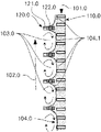
- FIG. 1 a schematic illustration of a functioning of a contactor
- FIG. 2 a schematic illustration of a first embodiment, formed as counter-current contactor
- FIG. 3 a a schematic illustration of a second embodiment, formed as counter-current contactor
- FIG. 3 b a schematic illustration of a third embodiment, formed as counter-current contactor
- FIG. 4 a schematic illustration of a fourth embodiment, with a stepped structure
- FIG. 5 a a schematic illustration of a fifth embodiment, formed as cross-current contactor
- FIG. 5 b a schematic illustration of a sixth embodiment, formed as cross-current contactor
- FIG. 6 a schematic illustration of a seventh embodiment, formed as heat exchanger
- FIG. 7 a schematic illustration of an eighth embodiment, formed as counter-current contactor with angled ledges
- FIG. 8 a schematic illustration of a first embodiment of a monolith, with channels having a triangular cross-section
- FIG. 9 a schematic illustration of a second embodiment of a monolith, with channels having a hexagonal cross-section
- FIG. 10 a schematic illustration of a third embodiment of a monolith, with channels having a rectangular cross-section
- FIG. 11 a a schematic illustration of a contactor built of several monolith structures, comprising a liquid distributor and a liquid collector;
- FIG. 11 b a cutout of the contactor of FIG. 11 a with a focus on the liquid distributor
- FIG. 11 c a cutout of the contactor of FIG. 11 a with a focus on the liquid collector
- FIG. 12 schematic view of the layer-by-layer assembly of a contactor
- FIG. 13 a schematic illustration of a particularly preferred embodiment of a monolith according to FIG. 10 with a stepped structure for conducting the first fluid.
- FIG. 1 shows a schematic illustration of a functioning of a contactor.
- the contactor essentially consists of a structure 110 . 0 for conducting a first fluid and flow breakers in the form of several ledges 120 . 0 arranged in parallel.
- the ledges 120 . 0 are connected to the structure 110 . 0 .
- the contact zone 104 . 0 is provided, which is arranged to conduct a second fluid and to bring into contact the first and the second fluids.
- the structure 110 . 0 can be formed in different ways, as will be exemplified hereunder with different examples.
- the structure 110 . 0 may particularly consist of walls, capillaries, pores, tissue, that are preferably easily wettable by the first fluid.
- the ledges 120 . 0 comprise a region facing the structure, which can easily be wetted by the first fluid.
- the ledges 120 . 0 furthermore comprise a region facing away from the structure, which is hardly wettable by the first fluid. In this manner the first fluid should be kept away from the region, in which the second fluid flows in the opposite direction with high velocity, as the first fluid could be dragged away here by the second fluid.
- a first fluid in particular a liquid
- the second fluid in particular also a liquid or a gas, a vapor, etc.
- the phase boundaries or boundary surface 104 . 1 formed between the two fluids in this manner is indicated in FIG. 1 by a broken line and shows a bent form, as illustrated.
- the directions 101 . 0 and 102 . 0 are opposed to each other, which corresponds to a counter-current.
- FIG. 2 shows a schematic illustration of a first embodiment of a contactor 100 . 1 , formed as counter-current contactor.
- the contactor 100 . 1 substantially consists of a structure 110 . 1 and flow breakers in the form of several ledges 120 . 1 arranged in parallel.
- the structure 110 . 1 is substantially plate-shaped and consists of a tissue or an open-pored foam, through which the first fluid can flow in the direction 101 . 1 .
- the ledges 120 . 2 are connected to the structure 110 . 1 at regular intervals. The ratio between the ledge distances and the ledge heights is approximately 5:1 in this case.
- the structure 110 . 1 has ledges 120 .
- the second fluid flows in the direction 102 . 1 , substantially in the opposite direction of the first fluid.
- the second fluid is conducted over the bars on both sides of the structure 100 . 2 , so that a contacting between the two fluids can be achieved on both sides.
- FIG. 3 a shows a schematic illustration of a second embodiment of a contactor 100 . 2 , formed as counter-current contactor.
- the contactor 100 . 2 substantially consists of a structure 110 . 2 and flow breakers in the form of several ledges 120 . 2 arranged in parallel.
- the structure 110 . 2 is arranged substantially plate-shaped and comprises a series of bars 111 . 2 arranged in parallel, between which open capillaries are provided on both sides.
- the ledges 120 . 2 are connected to the structure 110 . 2 .
- the ledges 120 . 2 are arranged perpendicular to the bars 111 . 2 .
- the structure 100 . 2 has ledges 120 .
- the first fluid flows in the direction 101 . 2 between the bars 111 . 2 through the structure 110 . 2 , while the second fluid is conducted rectangularly to the ledges 120 . 2 and thus in parallel to the bars 111 . 2 .
- the second fluid is conducted on both sides of the structure 100 . 2 over the bars, so that a contacting of the two fluids can be achieved on both sides.
- FIG. 3 b shows a schematic illustration of a third embodiment of a contactor 100 . 3 , formed as counter-current contactor.
- the contactor 100 . 3 substantially consists of a structure 110 . 3 and flow breakers in the form of several ledges 120 . 3 arranged in parallel.
- the structure 110 . 3 only shows one-sided open capillaries in the present case, which are formed by the bars 111 . 3 .
- a first side of the structure 100 . 3 is connected analogously to the structure 100 . 2 through ledges 120 . 3
- the opposing second side of the structure 100 . 3 connected to a plate 112 . 3 .
- a ratio of the ledge distances and the ledge heights is approximately 5:1 in this example.
- the second fluid is thus exclusively conducted in the direction 102 . 3 over the first side.
- FIG. 4 shows a schematic illustration of a fourth embodiment of a contactor 100 . 4 , with a stepped structure.
- the contactor 100 . 4 substantially consists of a structure 110 . 4 and flow breakers in the form of several ledges 120 . 4 arranged in parallel.
- the structure 110 . 4 comprises a plurality of longitudinal stepped elements 113 . 4 . This are assembled in two layers. In a first layer, the elements 113 . 4 are arranged in parallel at regular intervals in such a manner that the steps of the elements 113 . 4 are facing each other.
- the second layer is built up identically. The two layers are now arranged in a manner that the step sides contact each other and the elements 113 . 4 of the first layer are oriented towards the elements 113 .
- a distance between two neighboring elements 113 . 4 of one layer is approximately one third of the distance between two neighboring ledges 120 . 4 .
- the ledges 120 . 4 are arranged at both sides of the structure 110 . 4 , whereby two ledges 120 . 4 are opposed to each other relative to the structure 110 . 4 .
- the elements 113 . 4 form an angle with the ledges 120 . 4 of approximately 45°.
- a ratio of the ledge distances and the ledge heights is approximately 7:1 in this example.
- the first fluid is conducted in the two planes of the structure in plane 101 . 4 .
- the first fluid is conducted in the one plane at an angle 45° relative to the ledges, and in the other plane at an angle of approximately ⁇ 45° or 315°, respectively. On average, the first fluid still flows in the opposite direction relative to the second fluid.
- the contactor 100 . 4 is thus a counter-current contactor.
- FIG. 5 a is a schematic illustration of a fifth embodiment of a contactor 100 . 5 , again formed as cross-current contactor.
- the contactor 100 . 5 substantially consists of a structure 110 . 5 and flow breakers in the form of several ledges 120 . 5 arranged in parallel.
- the structure 110 . 5 is built up identically as structure 110 . 3 , whereby several parallel bars 111 . 5 are arranged on a rear wall 112 . 5 .
- every third bar 111 . 5 is provided with a ledge 120 . 5 .
- every second, every fourth, every fifth, etc. bar 111 . 5 could be provided with a ledge 120 . 5 .
- a ratio of the ledge distances and ledge heights is approximately 7:1 in this example. While the first fluid is conducted between the bars 111 . 5 in the direction 101 . 5 , the second fluid is conducted in the direction 102 . 5 , both at a right angle relevant to the ledges 120 . 5 as well as to the direction 101 . 5 .
- FIG. 5 b shows a schematic illustration of a sixth embodiment of a contactor 100 . 6 , formed as cross-current contactor.
- the contactor 100 . 6 substantially consists of a structure 110 . 6 and flow breakers in the form of several ledges 120 . 6 arranged in parallel.
- the structure 110 . 6 only comprises the plate 112 . 6 , for instance in accordance with the contactor 100 . 5 .
- the plate 112 . 6 can be provided as tissue or even plate.
- the ledges 120 . 6 are arranged on the plate 112 . 6 parallel to one another. The ratio of the ledge distances and the ledges heights is approximately 6:1 in this example.
- FIG. 6 is a schematic illustration of a seventh embodiment, formed as heat exchanger, comprising two contactors 100 . 3 according to FIG. 3 b .
- the two contactors are arranged in a manner that the two plates 112 . 7 define an intermediate space through which a heat transfer medium can flow.
- FIG. 7 is a schematic illustration of an eighth embodiment of a contactor 100 . 8 , formed as counter-current contactor with angled ledges.
- the contactor 100 . 8 substantially consists of a structure 110 . 8 and flow breakers in the form of several ledges 120 . 8 arranged in parallel.
- the structure 110 . 8 comprises a plate 112 . 8 with ledges arranged on it in parallel, which are inclined relative to a flow direction 101 . 8 of the first fluid at an angle of approximately 5 to 10°.
- the structure 100 . 8 comprises a second plate 112 . 8 with identically arranged ledges 120 . 8 .
- the two plates 112 . 8 are opposed to the facing ledges 120 . 8 such that one direction of the ledges 120 .
- the ledges 120 . 8 of the first and the second plates 112 . 8 are spaced apart and thus form a flow space for the second fluid.
- the second fluid flows in the direction 102 . 8 and thus in the opposite direction 101 . 8 of the first fluid.
- a rotational movement above an axis in the direction 102 . 8 is induced in the flow of the second fluid, which is suitable to intensify a blending in the second fluid.
- the contactors described above can be assembled modularly in a manner that a larger monolith structure is achieved.
- FIG. 8 shows a schematic illustration of a first embodiment of a monolith 100 . 9 , with channels having a triangular cross-section.
- the monolith 100 . 9 substantially consists of a structure 110 . 9 and flow breakers in the form of several ledges 120 . 9 arranged in parallel.
- the structure is made of an open-pored material in this example, which comprises a plurality of parallel channels in a flow direction 101 . 9 of the first fluid, through which the second fluid is conducted counter-currently to the first fluid.
- the channels have a triangular cross-section.
- ledges 120 . 9 protruding inwardly and circumferential ledges are arranged at regular intervals in a right angle relative to the flow direction 101 . 9 .
- FIG. 9 shows a schematic illustration of a second embodiment of a monolith 100 . 10 , with channels having a hexagonal cross-section.
- the monolith 100 . 10 is substantially assembled identically as the monolith 100 . 9 , whereby the channels have a hexagonal cross-section and are thus formed in a honeycomb shape.
- ledges 120 . 10 protruding inwardly and circumferential ledges are arranged at regular intervals in a right angle relative to the flow direction 101 . 10 .
- FIG. 10 shows a schematic illustration of a third embodiment of a monolith 100 . 11 , with channels having a rectangular cross-section.
- the monolith 100 . 11 is substantially assembled in the same way as the monolith 100 . 9 , whereby the channels have a rectangular cross-section.
- ledges 120 . 11 protruding inwardly and circumferential ledges are arranged at regular intervals in a right angle relative to the flow direction 101 . 11 .
- channels of the monoliths can also comprise differently shaped cross-sectional surfaces, for instance pentagonal, circular, rectangular, slit-shaped, etc.
- FIG. 11 a shows a schematic illustration of a monolith 100 . 12 according to one of the FIG. 8 to 10 or 13 , comprising a liquid distributor 130 . 12 and a liquid collector 140 . 12 .
- the liquid distributor 130 . 2 is connected with the end of the monolith 100 . 12 in such a manner that a first fluid flowing in the direction 101 . 12 in the inlet of the liquid distributor 130 . 12 reaches the structure of the monolith 100 . 12 and can pass through it.
- a liquid collector 140 . 12 that is assembled in the same way as the liquid distributor 130 . 12 is arranged in a manner that the first fluid is collected when exiting the structure of the monolith 100 . 12 and discharged through a drainpipe.
- Both the liquid distributor 130 . 12 as well as the liquid collector 140 . 12 comprise a plurality of openings, which are in communication with the above described channels of the monoliths 100 . 12 , so that the second fluid can reach the channels through the liquid distributor 130 . 12 and can discharged from the channels again through the liquid collector 140 . 12 .
- FIG. 11 b shows a cutout of the contactor 100 . 12 according to FIG. 11 a with a focus on the liquid distributor 130 . 12 .
- FIG. 11 c shows a cutout of a contactor 100 . 12 according to FIG. 11 a with a focus on a liquid collector 140 . 12 .
- the structure may consist of aluminum oxide and is thus easily wettable, while the ledges are made of aluminum oxide on the inside, i.e. in the direction of the structure, and cerium dioxide on the outside, whereby the latter is poorly wettable.
- the skilled person also knows further suitable materials or coatings, respectively, with which a contactor can be produced.
- FIG. 12 finally shows a schematic illustration of a layered design of the contactor 1 .
- the contactor 1 has to step elements 2 a , 2 b .
- the first step element 2 a extends from the right bottom to top left
- the second step element 2 b extends from the bottom left to top right and is arranged in the level behind the first step element 2 a .
- the general flow direction T is from the bottom to the top. The division bottom/top was selected randomly, only serves for explaining the figure and is not have any functional relationship with the contactor 1 .
- the general flow direction T indicates that a fluid passing through the contactor 1 , has a first contact with the contactor 1 at the lower end, i.e.
- the step elements 2 a , 2 b are formed by a plurality of layers 2 , 2 ′, 2 ′′, 2 ′′′, 2 ′′′′, 2 ′′′′′, which provide the step elements 2 a , 2 b with an in total stepped structure.
- a first layer 2 is partially overlaid by a second layer 2 ′, which, in turn, is partially overlaid by a third layer 2 ′′.
- the degree of overlapping i.e.
- the share in the surface of a step of the first layer 2 which is cohesive with the surface share of the second layer 2 ′, is constant throughout the contactor 1 in this example.
- the individual layers 2 , 2 ′, 2 ′′, 2 ′′′, 2 ′′′′, 2 ′′′′′ form both the steps of the first step element 2 a as well as that of the second step element 2 b .
- the degree of overlapping is at approximately 50%, i.e. 50% of the surface of a layer extending perpendicularly to the main flow direction is in cohesive contact with a neighboring layer.
- the thickness of the layer i.e. the surfaces that are extending parallel to the main flow direction T, corresponds to the free surface not overlapped by the subsequent layer.
- the overlapped surface shares of a layer form a blend surface 5 .
- the blend surface 5 is cohesively connected in the finished contactor 1 .
- step elements 2 a , 2 b Exemplified with the example of layer 2 ′′′′ of the step elements 2 a , 2 b , this means that both steps that are lying in the layer 2 ′′′′ or in the surface area of the expansion axes X, Y form a joint layer. Between the steps of step elements 2 a , 2 b in the layer 2 ′′′′ recesses 12 are provided.
- the step elements 2 a , 2 b shown exemplary are extending reciprocally towards each other and are crossing at an angle of 90°, calculated on an assumed middle axle through all edges of the steps of a step element 2 a , 2 b.
- FIG. 13 shows a schematic illustration of another contractor or another monolith 100 . 13 .
- the further monolith 100 . 13 is a particularly preferred embodiment of the monolith 100 . 11 illustrated generally in FIG. 10 .
- the channels, in which the fluid is conducted also have a rectangular cross-section.
- ledges 120 . 13 protruding inwardly and circumferential ledges are arranged at regular intervals in a right angle relative to the flow direction 101 . 113 of the first fluid or in the flow direction of the second fluid 102 . 13 .
- the structure 110 . 13 for conducting the first fluid is formed as stepped structure, analogously to the embodiment shown in FIG. 4 .
- the monolith structure 100 is formed as stepped structure, analogously to the embodiment shown in FIG. 4 .
- the contactor 1 shown in FIG. 1 could also be produced as multiple, which produces a bigger contactor 1 with more step elements 2 a , 2 b .
- Such an element can be repeated as often as desired, for instance as an interval A, also with a different basic orientation, in order to produce a bigger contactor 1 .
- the layer thicknesses of the layers 2 , 2 ′, 2 ′′, 2 ′′′, 2 ′′′′, 2 ′′′′′ shown exemplary in FIG. 1 may vary from 30 ⁇ m to 10 mm.
- the layers 2 , 2 ′, 2 ′′, 2 ′′′, 2 ′′′′, 2 ′′′′′ have layer thicknesses of 500 ⁇ m.
- the tissue or the open-pored foam can also be provided as ordered capillary system, for instance in the form of step bars as shown in FIG. 4 .
- the open-pored material with a random structure shown in FIGS. 8, 9 and 10 can also be replaced by an ordered structure with regularly arranged capillaries and/or step bars.
- a device is provided, by means of which two fluids can be brought into contact with one another in a particularly efficient way, and with which a risk of flooding can be reduced.
Landscapes
- Chemical & Material Sciences (AREA)
- Chemical Kinetics & Catalysis (AREA)
- Organic Chemistry (AREA)
- Physics & Mathematics (AREA)
- Thermal Sciences (AREA)
- Physical Or Chemical Processes And Apparatus (AREA)
- Vaporization, Distillation, Condensation, Sublimation, And Cold Traps (AREA)
- Gas Separation By Absorption (AREA)
- Breakers (AREA)
- Infusion, Injection, And Reservoir Apparatuses (AREA)
- External Artificial Organs (AREA)
- Turbine Rotor Nozzle Sealing (AREA)
- Quick-Acting Or Multi-Walled Pipe Joints (AREA)
- Pipeline Systems (AREA)
Applications Claiming Priority (4)
| Application Number | Priority Date | Filing Date | Title |
|---|---|---|---|
| EP16163271.6A EP3225304A1 (de) | 2016-03-31 | 2016-03-31 | Kontakter |
| EP16163271 | 2016-03-31 | ||
| EP16163271.6 | 2016-03-31 | ||
| PCT/EP2017/056422 WO2017167591A1 (de) | 2016-03-31 | 2017-03-17 | Kontakter |
Related Parent Applications (1)
| Application Number | Title | Priority Date | Filing Date |
|---|---|---|---|
| PCT/EP2017/056422 A-371-Of-International WO2017167591A1 (de) | 2016-03-31 | 2017-03-17 | Kontakter |
Related Child Applications (1)
| Application Number | Title | Priority Date | Filing Date |
|---|---|---|---|
| US17/832,070 Continuation US11772065B2 (en) | 2016-03-31 | 2022-06-03 | Contactor |
Publications (2)
| Publication Number | Publication Date |
|---|---|
| US20190046949A1 US20190046949A1 (en) | 2019-02-14 |
| US11369939B2 true US11369939B2 (en) | 2022-06-28 |
Family
ID=55745561
Family Applications (2)
| Application Number | Title | Priority Date | Filing Date |
|---|---|---|---|
| US16/087,254 Active 2038-08-01 US11369939B2 (en) | 2016-03-31 | 2017-03-17 | Contacter |
| US17/832,070 Active US11772065B2 (en) | 2016-03-31 | 2022-06-03 | Contactor |
Family Applications After (1)
| Application Number | Title | Priority Date | Filing Date |
|---|---|---|---|
| US17/832,070 Active US11772065B2 (en) | 2016-03-31 | 2022-06-03 | Contactor |
Country Status (11)
| Country | Link |
|---|---|
| US (2) | US11369939B2 (pl) |
| EP (2) | EP3225304A1 (pl) |
| JP (2) | JP7501992B2 (pl) |
| KR (2) | KR102371442B1 (pl) |
| CN (1) | CN109070046B (pl) |
| BR (1) | BR112018069946B1 (pl) |
| ES (1) | ES2929634T3 (pl) |
| MX (1) | MX2018011882A (pl) |
| PL (1) | PL3436189T3 (pl) |
| RU (1) | RU2740493C2 (pl) |
| WO (1) | WO2017167591A1 (pl) |
Cited By (1)
| Publication number | Priority date | Publication date | Assignee | Title |
|---|---|---|---|---|
| US20220297081A1 (en) * | 2016-03-31 | 2022-09-22 | Hirschberg Engineering Ag | Contacter |
Families Citing this family (6)
| Publication number | Priority date | Publication date | Assignee | Title |
|---|---|---|---|---|
| US10605093B2 (en) * | 2016-07-12 | 2020-03-31 | General Electric Company | Heat transfer device and related turbine airfoil |
| CA3089738C (en) * | 2018-01-30 | 2023-03-14 | Ihi Corporation | Packing, method for manufacturing same, and liquid film-forming structure |
| FR3095129B1 (fr) | 2019-04-16 | 2021-03-12 | Air Liquide | Garnissage ondulé-croisé en mousse métallique |
| EP3819025A1 (en) * | 2019-11-05 | 2021-05-12 | Hirschberg Engineering AG | Grid-like symmetrical distributor or collector element |
| EP3819014A1 (en) | 2019-11-05 | 2021-05-12 | Hirschberg Engineering AG | Grid-like fractal distributor or collector element |
| CN113842869A (zh) * | 2021-09-24 | 2021-12-28 | 中国华能集团清洁能源技术研究院有限公司 | 一种吸收塔填料的制备方法及填料 |
Citations (25)
| Publication number | Priority date | Publication date | Assignee | Title |
|---|---|---|---|---|
| US2681269A (en) * | 1951-03-21 | 1954-06-15 | Socony Vacuum Oil Co Inc | Contacting apparatus |
| US3039752A (en) * | 1952-03-07 | 1962-06-19 | Kittel Walter | Contacting apparatus for rectifying and contacting columns |
| US3385575A (en) * | 1964-07-29 | 1968-05-28 | Raymond C. Hall | Gas liquid contacting apparatus |
| US3466019A (en) * | 1967-08-04 | 1969-09-09 | Ronald Priestley | Gas-liquid contact packing sheets |
| US3612494A (en) * | 1968-09-11 | 1971-10-12 | Kobe Steel Ltd | Gas-liquid contact apparatus |
| US3722185A (en) * | 1971-06-09 | 1973-03-27 | Fisher Klosterman Inc | Gas scrubbing method and apparatus |
| US3743256A (en) * | 1970-08-20 | 1973-07-03 | Bbc Brown Boveri & Cie | Device for evaporative cooling towers with wetted walls |
| US4133709A (en) * | 1977-03-14 | 1979-01-09 | Carrico Arnold J | Method of making flexible multi-columnar fluid treatment cellular apparatus |
| US4701287A (en) * | 1982-06-18 | 1987-10-20 | Manteufel Rolf P C | Apparatus for the exchange of material and/or heat between and/or for mixing of gaseous and/or liquid substances |
| US4769186A (en) * | 1987-03-17 | 1988-09-06 | Energair Research And Development | Gas liquid tower structure |
| US5624733A (en) * | 1995-06-27 | 1997-04-29 | The Boc Group, Inc. | Structured packing |
| US20010051119A1 (en) | 1998-05-29 | 2001-12-13 | Rudolf A. Overbeek | Structured packing and element therefor |
| US20020026998A1 (en) | 1999-04-19 | 2002-03-07 | Roger Paulman | Fin array for heat transfer assemblies and method of making same |
| US6565629B1 (en) * | 1998-12-28 | 2003-05-20 | Nippon Sanso Corporation | Vapor-liquid contactor, cryogenic air separation unit and method of gas separation |
| US20060016216A1 (en) | 2004-07-23 | 2006-01-26 | Tonkovich Anna L | Distillation process using microchannel technology |
| US7195059B2 (en) | 2003-05-06 | 2007-03-27 | H2Gen Innovations, Inc. | Heat exchanger and method of performing chemical processes |
| US20090285956A1 (en) | 2008-05-15 | 2009-11-19 | Landers Jerry L | Heat exchanger, particularly for use in a beverage dispenser |
| US20100220985A1 (en) | 2007-10-18 | 2010-09-02 | Stego-Holding Gmbh | Heating device and heat exchanger |
| US20110105304A1 (en) | 2008-07-03 | 2011-05-05 | L'air Liquide Societe Anonyme Pour L'etude Et L'ex Ploitation Des Procedes Georges Claude | Ceramic Foams with Gradients of Composition in Heterogeneous Catalytic |
| US7976783B2 (en) * | 2004-11-23 | 2011-07-12 | Tribute Creations, Llc | Reactor with jet impingment heat transfer |
| WO2013120551A1 (en) | 2012-02-14 | 2013-08-22 | Sulzer Chemtech Ag | An extraction column and process for use thereof |
| WO2014043823A1 (de) | 2012-09-21 | 2014-03-27 | Hirschberg Engineering | Dreidimensionale formkörper |
| JP2014109391A (ja) | 2012-11-30 | 2014-06-12 | Toyota Motor Corp | 熱交換器 |
| WO2016095059A1 (de) | 2014-12-19 | 2016-06-23 | Hirschberg Engineering | Verfahren und vorrichtung zu schichtweisen aufbau von formkörpern |
| US20170014797A1 (en) * | 2014-04-01 | 2017-01-19 | Ihi Corporation | Method of manufacturing packing and packing |
Family Cites Families (3)
| Publication number | Priority date | Publication date | Assignee | Title |
|---|---|---|---|---|
| CN1280005C (zh) * | 2001-05-07 | 2006-10-18 | 环球油品公司 | 用于将至少两种流体混合和反应的设备 |
| US20120218857A1 (en) * | 2011-02-28 | 2012-08-30 | Uchicago Argonne, Llc | Microfluidic mixer, method for mixing fluids |
| EP3225304A1 (de) * | 2016-03-31 | 2017-10-04 | Hirschberg Engineering | Kontakter |
-
2016
- 2016-03-31 EP EP16163271.6A patent/EP3225304A1/de not_active Withdrawn
-
2017
- 2017-03-17 JP JP2018551780A patent/JP7501992B2/ja active Active
- 2017-03-17 KR KR1020187031680A patent/KR102371442B1/ko active Active
- 2017-03-17 PL PL17710573.1T patent/PL3436189T3/pl unknown
- 2017-03-17 EP EP17710573.1A patent/EP3436189B1/de active Active
- 2017-03-17 RU RU2018137614A patent/RU2740493C2/ru active
- 2017-03-17 CN CN201780024473.7A patent/CN109070046B/zh active Active
- 2017-03-17 ES ES17710573T patent/ES2929634T3/es active Active
- 2017-03-17 WO PCT/EP2017/056422 patent/WO2017167591A1/de not_active Ceased
- 2017-03-17 BR BR112018069946-2A patent/BR112018069946B1/pt active IP Right Grant
- 2017-03-17 US US16/087,254 patent/US11369939B2/en active Active
- 2017-03-17 KR KR1020227001006A patent/KR102506901B1/ko active Active
- 2017-03-17 MX MX2018011882A patent/MX2018011882A/es unknown
-
2022
- 2022-02-08 JP JP2022017570A patent/JP2022068235A/ja active Pending
- 2022-06-03 US US17/832,070 patent/US11772065B2/en active Active
Patent Citations (32)
| Publication number | Priority date | Publication date | Assignee | Title |
|---|---|---|---|---|
| US2681269A (en) * | 1951-03-21 | 1954-06-15 | Socony Vacuum Oil Co Inc | Contacting apparatus |
| US3039752A (en) * | 1952-03-07 | 1962-06-19 | Kittel Walter | Contacting apparatus for rectifying and contacting columns |
| US3385575A (en) * | 1964-07-29 | 1968-05-28 | Raymond C. Hall | Gas liquid contacting apparatus |
| US3466019A (en) * | 1967-08-04 | 1969-09-09 | Ronald Priestley | Gas-liquid contact packing sheets |
| US3612494A (en) * | 1968-09-11 | 1971-10-12 | Kobe Steel Ltd | Gas-liquid contact apparatus |
| US3743256A (en) * | 1970-08-20 | 1973-07-03 | Bbc Brown Boveri & Cie | Device for evaporative cooling towers with wetted walls |
| US3722185A (en) * | 1971-06-09 | 1973-03-27 | Fisher Klosterman Inc | Gas scrubbing method and apparatus |
| US4133709A (en) * | 1977-03-14 | 1979-01-09 | Carrico Arnold J | Method of making flexible multi-columnar fluid treatment cellular apparatus |
| US4701287A (en) * | 1982-06-18 | 1987-10-20 | Manteufel Rolf P C | Apparatus for the exchange of material and/or heat between and/or for mixing of gaseous and/or liquid substances |
| US4769186A (en) * | 1987-03-17 | 1988-09-06 | Energair Research And Development | Gas liquid tower structure |
| US5624733A (en) * | 1995-06-27 | 1997-04-29 | The Boc Group, Inc. | Structured packing |
| US20010051119A1 (en) | 1998-05-29 | 2001-12-13 | Rudolf A. Overbeek | Structured packing and element therefor |
| JP2002516745A (ja) | 1998-05-29 | 2002-06-11 | エービービー ラーマス グローバル インコーポレイテッド | 構造化されたパッキング及びその構成部品 |
| US6565629B1 (en) * | 1998-12-28 | 2003-05-20 | Nippon Sanso Corporation | Vapor-liquid contactor, cryogenic air separation unit and method of gas separation |
| US20020026998A1 (en) | 1999-04-19 | 2002-03-07 | Roger Paulman | Fin array for heat transfer assemblies and method of making same |
| US7195059B2 (en) | 2003-05-06 | 2007-03-27 | H2Gen Innovations, Inc. | Heat exchanger and method of performing chemical processes |
| JP2012130918A (ja) | 2004-07-23 | 2012-07-12 | Velocys Inc | マイクロチャネル技術を用いる蒸留プロセス |
| US20060016216A1 (en) | 2004-07-23 | 2006-01-26 | Tonkovich Anna L | Distillation process using microchannel technology |
| US7976783B2 (en) * | 2004-11-23 | 2011-07-12 | Tribute Creations, Llc | Reactor with jet impingment heat transfer |
| US20100220985A1 (en) | 2007-10-18 | 2010-09-02 | Stego-Holding Gmbh | Heating device and heat exchanger |
| CN103256717A (zh) | 2007-10-18 | 2013-08-21 | 斯特格控股有限公司 | 热交换器和加热设备 |
| US20090285956A1 (en) | 2008-05-15 | 2009-11-19 | Landers Jerry L | Heat exchanger, particularly for use in a beverage dispenser |
| CN101603753A (zh) | 2008-05-15 | 2009-12-16 | 曼尼托沃食品服务有限公司 | 特别用于饮料分配器的热交换器 |
| US20110105304A1 (en) | 2008-07-03 | 2011-05-05 | L'air Liquide Societe Anonyme Pour L'etude Et L'ex Ploitation Des Procedes Georges Claude | Ceramic Foams with Gradients of Composition in Heterogeneous Catalytic |
| CN102083770A (zh) | 2008-07-03 | 2011-06-01 | 乔治洛德方法研究和开发液化空气有限公司 | 多相催化中的具有组成梯度的陶瓷泡沫 |
| WO2013120551A1 (en) | 2012-02-14 | 2013-08-22 | Sulzer Chemtech Ag | An extraction column and process for use thereof |
| WO2014043823A1 (de) | 2012-09-21 | 2014-03-27 | Hirschberg Engineering | Dreidimensionale formkörper |
| US20150246484A1 (en) | 2012-09-21 | 2015-09-03 | Hirschberg Engineering | Three-dimensional moulding |
| JP2014109391A (ja) | 2012-11-30 | 2014-06-12 | Toyota Motor Corp | 熱交換器 |
| US20170014797A1 (en) * | 2014-04-01 | 2017-01-19 | Ihi Corporation | Method of manufacturing packing and packing |
| WO2016095059A1 (de) | 2014-12-19 | 2016-06-23 | Hirschberg Engineering | Verfahren und vorrichtung zu schichtweisen aufbau von formkörpern |
| US20170348912A1 (en) | 2014-12-19 | 2017-12-07 | Hirschberg Engineering | Layer-by-layer production of molded articles |
Non-Patent Citations (1)
| Title |
|---|
| Piani, L. et al. "Sodium Tripolyphosphate and Polyphosphate as Dispersing Agents for Alumina Suspensions: Rheological Characterization" Journal of Engineering, 2013, pp. 1-4, vol. 2013, Article ID 930832. |
Cited By (2)
| Publication number | Priority date | Publication date | Assignee | Title |
|---|---|---|---|---|
| US20220297081A1 (en) * | 2016-03-31 | 2022-09-22 | Hirschberg Engineering Ag | Contacter |
| US11772065B2 (en) * | 2016-03-31 | 2023-10-03 | Hirschberg Engineering Ag | Contactor |
Also Published As
| Publication number | Publication date |
|---|---|
| RU2018137614A (ru) | 2020-04-30 |
| CN109070046B (zh) | 2020-12-25 |
| US20220297081A1 (en) | 2022-09-22 |
| US11772065B2 (en) | 2023-10-03 |
| BR112018069946A2 (pt) | 2019-02-05 |
| ES2929634T3 (es) | 2022-11-30 |
| JP2022068235A (ja) | 2022-05-09 |
| CN109070046A (zh) | 2018-12-21 |
| RU2018137614A3 (pl) | 2020-04-30 |
| KR102371442B1 (ko) | 2022-03-08 |
| EP3436189B1 (de) | 2022-10-05 |
| PL3436189T3 (pl) | 2023-02-06 |
| KR102506901B1 (ko) | 2023-03-07 |
| EP3225304A1 (de) | 2017-10-04 |
| EP3436189A1 (de) | 2019-02-06 |
| US20190046949A1 (en) | 2019-02-14 |
| KR20220010067A (ko) | 2022-01-25 |
| MX2018011882A (es) | 2019-01-10 |
| BR112018069946B1 (pt) | 2022-05-17 |
| RU2740493C2 (ru) | 2021-01-14 |
| WO2017167591A1 (de) | 2017-10-05 |
| JP2019515782A (ja) | 2019-06-13 |
| KR20180132781A (ko) | 2018-12-12 |
| JP7501992B2 (ja) | 2024-06-18 |
Similar Documents
| Publication | Publication Date | Title |
|---|---|---|
| US11772065B2 (en) | Contactor | |
| EP2897783B1 (de) | Dreidimensionale formkörper | |
| US9440216B2 (en) | Minimal surface area mass and heat transfer packing | |
| RU2181623C2 (ru) | Насадка с перекрестно-канальной структурой, а также набивная колонна и смесительное устройство с такой насадкой | |
| Sahin et al. | Partitioned EDGE devices for high throughput production of monodisperse emulsion droplets with two distinct sizes | |
| JP2019089067A (ja) | 比較的単分散の液滴を形成するためのデバイスおよび方法 | |
| JP6855765B2 (ja) | 気液接触装置 | |
| JP2014508037A (ja) | アブソーバ | |
| CN108525715B (zh) | 微流道结构、微流控芯片和用于液滴定量包裹微球的方法 | |
| JPWO2019207671A1 (ja) | 気液接触装置 | |
| JP2007509751A (ja) | 格子流下膜脱蔵装置 | |
| US10786752B2 (en) | Exchange column distributor tray comprising a dispersive material within a chimney for gas passage | |
| EP4021603B1 (en) | Grid-like fractal distributor or collector element | |
| JP2023501300A (ja) | 格子状の対称な分配要素または収集要素 | |
| JP7167513B2 (ja) | 気液接触装置 | |
| KR20010043888A (ko) | 구조화된 패킹 및 이를 위한 소자 | |
| JP7243057B2 (ja) | 気液接触装置 | |
| US10272354B2 (en) | Liquid distributor of a process-technology column | |
| Şahin | Upscaling microstructured emulsification devices | |
| WO2025207170A2 (en) | Manifold design for uniform flow | |
| JP2022020380A (ja) | 液液混相流路群を形成させる方法、及び液液混相流路群の形成・消滅を制御する方法並びにそのためのモジュール |
Legal Events
| Date | Code | Title | Description |
|---|---|---|---|
| AS | Assignment |
Owner name: HIRSCHBERG ENGINEERING, SWITZERLAND Free format text: ASSIGNMENT OF ASSIGNORS INTEREST;ASSIGNOR:HIRSCHBERG, SEBASTIAN;REEL/FRAME:046936/0615 Effective date: 20180919 |
|
| FEPP | Fee payment procedure |
Free format text: ENTITY STATUS SET TO UNDISCOUNTED (ORIGINAL EVENT CODE: BIG.); ENTITY STATUS OF PATENT OWNER: SMALL ENTITY |
|
| FEPP | Fee payment procedure |
Free format text: ENTITY STATUS SET TO SMALL (ORIGINAL EVENT CODE: SMAL); ENTITY STATUS OF PATENT OWNER: SMALL ENTITY |
|
| STPP | Information on status: patent application and granting procedure in general |
Free format text: DOCKETED NEW CASE - READY FOR EXAMINATION |
|
| AS | Assignment |
Owner name: HIRSCHBERG ENGINEERING AG, SWITZERLAND Free format text: ASSIGNMENT OF ASSIGNORS INTEREST;ASSIGNOR:HIRSCHBERG ENGINEERING;REEL/FRAME:049484/0419 Effective date: 20190616 |
|
| STPP | Information on status: patent application and granting procedure in general |
Free format text: RESPONSE TO NON-FINAL OFFICE ACTION ENTERED AND FORWARDED TO EXAMINER |
|
| STPP | Information on status: patent application and granting procedure in general |
Free format text: NON FINAL ACTION MAILED |
|
| STPP | Information on status: patent application and granting procedure in general |
Free format text: RESPONSE TO NON-FINAL OFFICE ACTION ENTERED AND FORWARDED TO EXAMINER |
|
| STPP | Information on status: patent application and granting procedure in general |
Free format text: FINAL REJECTION MAILED |
|
| STPP | Information on status: patent application and granting procedure in general |
Free format text: NOTICE OF ALLOWANCE MAILED -- APPLICATION RECEIVED IN OFFICE OF PUBLICATIONS |
|
| STPP | Information on status: patent application and granting procedure in general |
Free format text: PUBLICATIONS -- ISSUE FEE PAYMENT VERIFIED |
|
| STCF | Information on status: patent grant |
Free format text: PATENTED CASE |
|
| FEPP | Fee payment procedure |
Free format text: MAINTENANCE FEE REMINDER MAILED (ORIGINAL EVENT CODE: REM.); ENTITY STATUS OF PATENT OWNER: SMALL ENTITY |