US11391663B2 - Particle analyzing apparatus, particle separating device, particle analysis method, and particle separating method - Google Patents
Particle analyzing apparatus, particle separating device, particle analysis method, and particle separating method Download PDFInfo
- Publication number
- US11391663B2 US11391663B2 US16/467,712 US201716467712A US11391663B2 US 11391663 B2 US11391663 B2 US 11391663B2 US 201716467712 A US201716467712 A US 201716467712A US 11391663 B2 US11391663 B2 US 11391663B2
- Authority
- US
- United States
- Prior art keywords
- particle
- analyte
- particles
- magnetic susceptibility
- magnetic
- Prior art date
- Legal status (The legal status is an assumption and is not a legal conclusion. Google has not performed a legal analysis and makes no representation as to the accuracy of the status listed.)
- Active, expires
Links
Images






Classifications
-
- B—PERFORMING OPERATIONS; TRANSPORTING
- B03—SEPARATION OF SOLID MATERIALS USING LIQUIDS OR USING PNEUMATIC TABLES OR JIGS; MAGNETIC OR ELECTROSTATIC SEPARATION OF SOLID MATERIALS FROM SOLID MATERIALS OR FLUIDS; SEPARATION BY HIGH-VOLTAGE ELECTRIC FIELDS
- B03C—MAGNETIC OR ELECTROSTATIC SEPARATION OF SOLID MATERIALS FROM SOLID MATERIALS OR FLUIDS; SEPARATION BY HIGH-VOLTAGE ELECTRIC FIELDS
- B03C1/00—Magnetic separation
- B03C1/02—Magnetic separation acting directly on the substance being separated
- B03C1/025—High gradient magnetic separators
- B03C1/031—Component parts; Auxiliary operations
- B03C1/033—Component parts; Auxiliary operations characterised by the magnetic circuit
- B03C1/0332—Component parts; Auxiliary operations characterised by the magnetic circuit using permanent magnets
-
- B—PERFORMING OPERATIONS; TRANSPORTING
- B03—SEPARATION OF SOLID MATERIALS USING LIQUIDS OR USING PNEUMATIC TABLES OR JIGS; MAGNETIC OR ELECTROSTATIC SEPARATION OF SOLID MATERIALS FROM SOLID MATERIALS OR FLUIDS; SEPARATION BY HIGH-VOLTAGE ELECTRIC FIELDS
- B03C—MAGNETIC OR ELECTROSTATIC SEPARATION OF SOLID MATERIALS FROM SOLID MATERIALS OR FLUIDS; SEPARATION BY HIGH-VOLTAGE ELECTRIC FIELDS
- B03C1/00—Magnetic separation
- B03C1/02—Magnetic separation acting directly on the substance being separated
- B03C1/28—Magnetic plugs and dipsticks
- B03C1/288—Magnetic plugs and dipsticks disposed at the outer circumference of a recipient
-
- G—PHYSICS
- G01—MEASURING; TESTING
- G01N—INVESTIGATING OR ANALYSING MATERIALS BY DETERMINING THEIR CHEMICAL OR PHYSICAL PROPERTIES
- G01N15/00—Investigating characteristics of particles; Investigating permeability, pore-volume or surface-area of porous materials
- G01N15/02—Investigating particle size or size distribution
-
- G—PHYSICS
- G01—MEASURING; TESTING
- G01N—INVESTIGATING OR ANALYSING MATERIALS BY DETERMINING THEIR CHEMICAL OR PHYSICAL PROPERTIES
- G01N15/00—Investigating characteristics of particles; Investigating permeability, pore-volume or surface-area of porous materials
- G01N15/02—Investigating particle size or size distribution
- G01N15/0205—Investigating particle size or size distribution by optical means
- G01N15/0227—Investigating particle size or size distribution by optical means using imaging; using holography
-
- G—PHYSICS
- G01—MEASURING; TESTING
- G01N—INVESTIGATING OR ANALYSING MATERIALS BY DETERMINING THEIR CHEMICAL OR PHYSICAL PROPERTIES
- G01N15/00—Investigating characteristics of particles; Investigating permeability, pore-volume or surface-area of porous materials
- G01N15/10—Investigating individual particles
- G01N15/1031—Investigating individual particles by measuring electrical or magnetic effects
-
- G—PHYSICS
- G01—MEASURING; TESTING
- G01N—INVESTIGATING OR ANALYSING MATERIALS BY DETERMINING THEIR CHEMICAL OR PHYSICAL PROPERTIES
- G01N27/00—Investigating or analysing materials by the use of electric, electrochemical, or magnetic means
- G01N27/72—Investigating or analysing materials by the use of electric, electrochemical, or magnetic means by investigating magnetic variables
- G01N27/74—Investigating or analysing materials by the use of electric, electrochemical, or magnetic means by investigating magnetic variables of fluids
- G01N27/76—Investigating or analysing materials by the use of electric, electrochemical, or magnetic means by investigating magnetic variables of fluids by investigating susceptibility
-
- G—PHYSICS
- G01—MEASURING; TESTING
- G01N—INVESTIGATING OR ANALYSING MATERIALS BY DETERMINING THEIR CHEMICAL OR PHYSICAL PROPERTIES
- G01N15/00—Investigating characteristics of particles; Investigating permeability, pore-volume or surface-area of porous materials
- G01N2015/0042—Investigating dispersion of solids
- G01N2015/0046—Investigating dispersion of solids in gas, e.g. smoke
-
- G—PHYSICS
- G01—MEASURING; TESTING
- G01N—INVESTIGATING OR ANALYSING MATERIALS BY DETERMINING THEIR CHEMICAL OR PHYSICAL PROPERTIES
- G01N15/00—Investigating characteristics of particles; Investigating permeability, pore-volume or surface-area of porous materials
- G01N2015/0042—Investigating dispersion of solids
- G01N2015/0053—Investigating dispersion of solids in liquids, e.g. trouble
-
- G—PHYSICS
- G01—MEASURING; TESTING
- G01N—INVESTIGATING OR ANALYSING MATERIALS BY DETERMINING THEIR CHEMICAL OR PHYSICAL PROPERTIES
- G01N15/00—Investigating characteristics of particles; Investigating permeability, pore-volume or surface-area of porous materials
- G01N15/10—Investigating individual particles
- G01N2015/1027—Determining speed or velocity of a particle
-
- G—PHYSICS
- G01—MEASURING; TESTING
- G01N—INVESTIGATING OR ANALYSING MATERIALS BY DETERMINING THEIR CHEMICAL OR PHYSICAL PROPERTIES
- G01N15/00—Investigating characteristics of particles; Investigating permeability, pore-volume or surface-area of porous materials
- G01N15/10—Investigating individual particles
- G01N2015/1029—Particle size
Definitions
- the present invention relates to particle analyzing apparatuses, particle separating devices, particle analysis methods, and particle separating methods.
- the present inventors have in the past proposed a device and a method for measuring the porosity of a particle using the volume magnetic susceptibility (magnetic susceptibility per unit volume) of the particle (Patent Literature 1).
- the present inventors have also in the past proposed a device and a method for measuring the surface area of a particle, the average value of the diameters of small holes formed in the particle, the average value of the depths of the small holes, the average value of the volumes of the small holes, and the number of the small holes, using the volume magnetic susceptibility of the particle (Patent Literature 2).
- the present inventors have further studied the volume magnetic susceptibility of particles to find that in the case where particles have a plurality of crystal forms, a difference in crystal form influences the volume magnetic susceptibility, and have completed the present invention.
- a particle analyzing apparatus includes a processor and storage.
- the processor acquires a volume magnetic susceptibility of an analyte particle.
- the storage stores reference data.
- the reference data indicates a volume magnetic susceptibility of a reference particle of the same type as a type of the analyte particle for each of possible crystal forms of the analyte particle.
- the processor determines a crystal form of the analyte particle on the basis of the volume magnetic susceptibility of the analyte particle and the reference data.
- the reference data indicates a relationship between a particle diameter and the volume magnetic susceptibility of the reference particle for each of the possible crystal forms of the analyte particle.
- the processor acquires a particle diameter and the volume magnetic susceptibility of the analyte particle, and determines the crystal form of the analyte particle on the basis of the particle diameter and the volume magnetic susceptibility of the analyte particle and the reference data.
- a particle separating device separates particles according to possible crystal form of the particles.
- the particle separating device includes a particle trapping section.
- the particle trapping section generates a gradient of a magnetic flux density, and applies a magnetic force to the particles in a direction opposite to a direction in which a liquid medium containing the particles flows.
- the particle trapping section traps a particle having a particular crystal form among the particles using the magnetic force.
- the plurality of particle trapping sections are arranged in a row extending in the direction in which the liquid medium flows.
- the plurality of particle trapping sections generate magnetic fields each having a different value B(dB/dx) of a product of the magnetic flux density and the gradient of the magnetic flux density.
- a particle analysis method includes acquiring a volume magnetic susceptibility of an analyte particle, and determining a crystal form of the analyte particle on the basis of the volume magnetic susceptibility of the analyte particle and reference data.
- the reference data indicates a volume magnetic susceptibility of a reference particle of the same type as a type of the analyte particle for each of possible crystal forms of the analyte particle.
- the particle analysis method further includes acquiring a particle diameter of the analyte particle.
- the reference data indicates a relationship between a particle diameter and the volume magnetic susceptibility of the reference particle for each of the possible crystal forms of the analyte particle.
- the crystal form of the analyte particle is determined on the basis of the particle diameter and the volume magnetic susceptibility of the analyte particle and the reference data.
- a particle separating method separates particles according to possible crystal form of the particles.
- the particle separating method includes applying a magnetic force to the particles in a direction opposite to a direction in which a liquid medium containing the particles flows, using a gradient of a magnetic flux density. In the applying a magnetic force to the particles, a particle having a particular crystal form is trapped among the particles using the magnetic force.
- the particle separating method further includes preparing the liquid medium having a volume magnetic susceptibility that allows the particle having the particular crystal form to be trapped.
- the crystal form of a particle can be determined.
- a particle can be separated according to crystal form.
- FIG. 1 is a schematic diagram of a particle analyzing apparatus according to a first embodiment of the present invention.
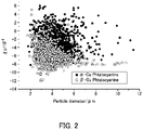
- FIG. 2 is a diagram showing a result of measurement of the volume magnetic susceptibility of copper phthalocyanine.
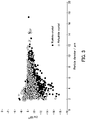
- FIG. 3 is a diagram showing a result of measurement of the volume magnetic susceptibility of theophylline.
- FIGS. 4A and 4B are diagrams showing motion of a particle according to the first embodiment of the present invention.
- FIG. 5 is a diagram showing a configuration of the particle analyzing apparatus of the first embodiment of the present invention.
- FIG. 6 is a diagram showing an example of reference data according to the first embodiment of the present invention.
- FIG. 7 is a flowchart showing a particle analysis method according to the first embodiment of the present invention.
- FIG. 8 is a diagram showing a configuration of a particle separating device according to a second embodiment of the present invention.
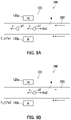
- FIG. 9A is a diagram showing motion of a first particle according to the second embodiment of the present invention
- FIG. 9B is a diagram showing motion of a second particle according to the second embodiment of the present invention.
- FIG. 10 is a flowchart showing a particle separating method according to the second embodiment of the present invention.
- FIG. 11 is a diagram showing a configuration of a particle separating device according to a third embodiment of the present invention.
- FIG. 1 is a schematic diagram of a particle analyzing apparatus 10 of this embodiment.
- the particle analyzing apparatus 10 determines the crystal form of a particle p.
- the particle analyzing apparatus 10 includes a magnetic field generating section 20 , a detection section 30 , and a calculation section 40 .
- a cell 21 is disposed near the magnetic field generating section 20 .
- the magnetic field generating section 20 subjects the particle p in the cell 21 to magnetophoresis.
- the particle p exhibits crystallinity.
- a particle exhibiting crystallinity is also hereinafter referred to as a “crystal particle.”
- the detection section 30 detects the particle p in the cell 21 .
- the calculation section 40 acquires the particle diameter and the magnetophoretic velocity of the particle p, from a result of the detection by the detection section 30 .
- the calculation section 40 also measures the volume magnetic susceptibility of the particle p on the basis of the particle diameter and the magnetophoretic velocity of the particle p. Thereafter, the calculation section 40 determines the crystal form of the particle p on the basis of the particle diameter and the volume magnetic susceptibility of the particle p.
- the magnetic field generating section 20 generates a magnetic field gradient (a gradient of a magnetic flux density) to apply a magnetic force to the particle p in the cell 21 .
- the particle p is subjected to magnetophoresis.
- the magnetic field generating section 20 includes a pair of permanent magnets that generates a magnetic field gradient.
- the two permanent magnets in the permanent magnet pair are spaced apart from each other by a predetermined distance of, for example, not less than 100 ⁇ m and not more than 500 ⁇ m.
- the cell 21 is disposed in the space between the two permanent magnets.
- the cell 21 is a capillary tube.
- the capillary tube is an example tubular member.
- the material for the cell 21 is not particularly limited if the material can transmit visible light or laser light.
- the cell 21 may be made of glass or plastic.
- the particle p is present in a medium m.
- a single particle p may be present in the medium m, or a plurality of particles p may be present in the medium m. In the case where a plurality of particles p are present in the medium m, the plurality of particles p may be dispersed in the medium m or may be non-uniformly distributed in the medium m.
- the medium m may be liquid or gas.
- the medium m may, for example, be selected from water, methanol, ethanol, 1-propanol, acetonitrile, and acetone.
- the medium m may, for example, be a mixture of two or more of water, methanol, ethanol, 1-propanol, acetonitrile, and acetone.
- the medium m may, for example, be air.
- the particle p is introduced together with the medium m into the cell 21 using, for example, a microsyringe or a micropump.
- the particle p may be introduced together with the medium m into the cell 21 using the siphon principle.
- a droplet (solution) containing the particle p may be introduced into the cell 21 (capillary tube) through capillary action. When a droplet containing the particle p is dropped onto an end of the capillary tube, the droplet flows in the capillary tube through capillary action.
- Particles p that are analyzed have different crystal forms (a plurality of crystal forms). For example, particles p may exhibit different crystal structures as different crystal forms. Particles p may also exhibit anhydride crystal and hydrate crystal as different crystal forms. Particles p may also exhibit different organic solvate crystals in which organic solvent molecules are bonded together as different crystal forms.
- Examples of the particle p can include copper phthalocyanine and theophylline.
- Copper phthalocyanine is known as a component of blue pigments.
- Theophylline is known as a component of medicines used in treatment of respiratory system diseases such as bronchial asthma, chronic bronchitis, and chronic obstructive pulmonary disease.
- Copper phthalocyanine exhibits different crystal structures as different crystal forms. Specifically, the crystal forms of copper phthalocyanine include ⁇ crystal and ⁇ crystal.
- Theophylline includes anhydride crystal and hydrate crystal as different crystal forms.
- a relationship (volume magnetic susceptibility distribution) between the particle diameter and the volume magnetic susceptibility of the particle p varies depending on the crystal form.
- the ⁇ crystal and the ⁇ crystal of copper phthalocyanine have different relationships (volume magnetic susceptibility distributions) between the particle diameter and the volume magnetic susceptibility (see FIG. 2 ).
- the particle analyzing apparatus 10 determines whether the crystal form of the particle p (copper phthalocyanine) is the ⁇ crystal or the ⁇ crystal.
- the hydrate crystal and the anhydride crystal of theophylline have different relationships (volume magnetic susceptibility distributions) between the particle diameter and the volume magnetic susceptibility (see FIG. 3 ).
- the particle analyzing apparatus 10 determines whether the crystal form of the particle p (theophylline) is the hydrate crystal or the anhydride crystal.
- the detection section 30 detects the particle p in the cell 21 , and generates a signal indicating a position and the particle diameter of the particle p in the cell 21 .
- the calculation section 40 measures the particle diameter and the magnetophoretic velocity of the particle p on the basis of the signal generated by the detection section 30 .
- the calculation section 40 includes storage 41 and a processor 42 .
- the storage 41 stores a program and setting information, etc.
- the storage 41 may include, for example, a hard disk drive (HDD), random access memory (RAM), and read only memory (ROM).
- the processor 42 executes the computer program stored in the storage 41 to perform various processes such as numerical calculation, information processing, and device control.
- the processor 42 may include, for example, a processor, such as a central processing unit (CPU) or a microprocessing unit (MPU).
- a general-purpose computer such as a personal computer, is used.
- the processor 42 acquires changes over time of the position of the particle p from the signal generated by the detection section 30 .
- the detection section 30 detects the particle p in the cell 21 at predetermined time intervals. This allows measurement of the position of the particle p at different times.
- the processor 42 measures the magnetophoretic velocity of the particle p on the basis of changes over time of the position of the particle p.
- the processor 42 also measures the particle diameter of the particle p on the basis of the signal generated by the detection section 30 .
- the processor 42 measures the volume magnetic susceptibility of the particle p on the basis of the particle diameter and the magnetophoretic velocity of the particle p.
- the processor 42 calculates the volume magnetic susceptibility of the particle p on the basis of Expression (1) below.
- v ⁇ 2( ⁇ s ⁇ m ) r 2 /9 ⁇ o ⁇ B ( dB/dx ) (1)
- v represents the magnetophoretic velocity of the particle p
- ⁇ s represents the volume magnetic susceptibility of the particle p
- ⁇ m represents the volume magnetic susceptibility of the medium m
- r represents the radius of the particle p
- ⁇ represents the coefficient of viscosity of the medium m
- ⁇ o represents the magnetic permeability of vacuum
- B represents a magnetic flux density
- dB/dx represents a magnetic field gradient (the gradient of the magnetic flux density).
- the storage 41 stores reference data 43 .
- the reference data 43 indicates the relationship between the particle diameter and the volume magnetic susceptibility of a reference particle that is of the same type as that of the analyte particle p, for each of possible crystal forms of the analyte particle p (reference particle).
- the processor 42 determines the crystal form of the analyte particle p, on the basis of the particle diameter and the volume magnetic susceptibility of the analyte particle p, and the reference data 43 .
- the reference data 43 indicates a relationship between the particle diameter and the volume magnetic susceptibility of the ⁇ crystal, and a relationship between the particle diameter and the volume magnetic susceptibility of the ⁇ crystal.
- the reference data 43 indicates a relationship between the particle diameter and the volume magnetic susceptibility of the hydrate crystal, and a relationship between the particle diameter and the volume magnetic susceptibility of the anhydride crystal.
- FIGS. 4A and 4B are diagrams showing the motion of the particle p. Specifically, FIGS. 4A and 4B show a relationship between the volume magnetic susceptibilities of the particle p and the medium m and the direction of movement of the particle p.
- the magnetic field generating section 20 includes a permanent magnet 20 a whose magnetic pole is the north pole, and a permanent magnet 20 b whose magnetic pole is the south pole. The two permanent magnets 20 a and 20 b face each other with the cell 21 interposed therebetween.
- the particle p moves in a direction away from the magnetic field (the magnetic field generating section 20 ).
- the particle p moves toward the magnetic field (the magnetic field generating section 20 ).
- the motion of the particle p is determined on the basis of the volume magnetic susceptibilities of the particle p and the medium m.
- the particle p receives a force near ends of the permanent magnets 20 a and 20 b .
- the particle p receives a force in a range of about ⁇ 200 ⁇ m near the ends of the permanent magnets 20 a and 20 b.
- FIG. 5 is a diagram showing a configuration of the particle analyzing apparatus 10 .
- the particle analyzing apparatus 10 further includes a light source 50 .
- the detection section 30 includes a magnification section 32 and an imaging section 34 .
- the light source 50 emits relatively high-intensity light that contains a visible light component.
- the light source 50 irradiates the cell 21 with the light.
- the particle p is irradiated with the light.
- the light emitted by the light source 50 may have a relatively broad wavelength spectrum.
- a halogen lamp may be preferably used as the light source 50 .
- An image of the particle p introduced into the cell 21 is magnified by a suitable factor by the magnification section 32 and is captured by the imaging section 34 .
- the position of the particle p can be specified from a result of the image capture by the imaging section 34 (an image captured by the imaging section 34 ).
- the magnification section 32 includes an objective lens
- the imaging section 34 includes a charge-coupled device (CCD).
- each pixel of the imaging section 34 may include a photodiode or a photomultiplier tube.
- the imaging section 34 captures an image of the particle p at predetermined time intervals. Note that the imaging section 34 may capture light that has been emitted from the light source 50 and transmitted through the cell 21 , or light that has been emitted from the light source 50 and scattered by the particle p.
- the calculation section 40 (the processor 42 ) acquires changes over time of the position of the particle p from the result of image capture by the imaging section 34 , and measures the magnetophoretic velocity of the particle p on the basis of the changes over time of the position of the particle p.
- the calculation section 40 also measures the particle diameter of the particle p on the basis of the result of the image capture of the particle p.
- the calculation section 40 executes the following process. Specifically, initially, an image captured by the imaging section 34 is converted into a monochromatic image, and the luminance thereof is converted into numerical values. Next, the derivative values of the luminance values are compared with a threshold value to set the boundary of the particle p. Next, the area of the particle p is detected from the boundary thus set, and the particle diameter is calculated from the radius of a circle corresponding to the area.
- the center of the particle p is defined, a plurality of straight lines passing through the center of the particle p are drawn, a distance between two points where each straight line intersects with the boundary of the particle p is obtained, and an average of the thus obtained distances is calculated.
- FIG. 6 is a diagram showing an example of the reference data 43 . Specifically, FIG. 6 shows a relationship between the particle diameter and the volume magnetic susceptibility of a reference particle.
- the horizontal axis represents the particle diameter
- the vertical axis represents the volume magnetic susceptibility.
- a graph 430 shows the relationship between the particle diameter and the volume magnetic susceptibility of a reference particle for each of possible crystal forms of the reference particle.
- the storage 41 which has been described with reference to FIG. 1 , stores the reference data 43 corresponding to the graph 430 . Specifically, the storage 41 stores, as the reference data 43 , data indicating an expression of the graph 430 . Alternatively, the storage 41 stores, as the reference data 43 , data indicating a table corresponding to the graph 430 .
- the graph 430 includes a first graph 431 and a second graph 432 .
- the first graph 431 corresponds to a first crystal form indicating one of the two crystal forms
- the second graph 432 corresponds to a second crystal form indicating the other of the two crystal forms.
- the reference data 43 contains first reference data corresponding to the first graph 431 , and second reference data corresponding to the second graph 432 .
- the processor 42 which has been described with reference to FIG. 1 , when acquiring the particle diameter and the volume magnetic susceptibility of the analyte particle p, determines whether the crystal form of the analyte particle p is the first crystal form or the second crystal form, by referring to the first reference data and the second reference data.
- the processor 42 acquires the volume magnetic susceptibility of a reference particle that has the same particle diameter as that of the analyte particle p, from each of the first reference data and the second reference data.
- the volume magnetic susceptibility of a reference particle that has the same particle diameter as that of the analyte particle p is also hereinafter referred to as a “reference volume magnetic susceptibility.”
- the processor 42 determines which of the acquired reference volume magnetic susceptibilities is closest to the volume magnetic susceptibility of the analyte particle p. Based on a result of the determination, the processor 42 determines the crystal form of the analyte particle p.
- the reference data 43 may indicate a volume magnetic susceptibility range for each particle diameter.
- the processor 42 acquires, from the reference data 43 , the volume magnetic susceptibility range of a reference particle that has the same particle diameter as that of the analyte particle p, for each crystal form.
- the volume magnetic susceptibility range of a reference particle that has the same particle diameter as that of the analyte particle p is also hereinafter referred to as a “reference volume magnetic susceptibility range.”
- the processor 42 determines which of the acquired reference volume magnetic susceptibility ranges includes the value of the volume magnetic susceptibility of the analyte particle p.
- the reference data 43 may indicate a volume magnetic susceptibility range and a median of the volume magnetic susceptibility range for each particle diameter.
- the processor 42 acquires, from the reference data 43 , the volume magnetic susceptibility range (reference volume magnetic susceptibility range) and the median for a reference particle that has the same particle diameter as that of the analyte particle p, for each crystal form.
- the processor 42 determines which of the acquired reference volume magnetic susceptibility ranges includes the value of the volume magnetic susceptibility of the analyte particle p.
- the processor 42 determines which of the acquired medians is closest to the volume magnetic susceptibility of the analyte particle p.
- the reference data 43 may indicate an average value instead of the median.
- FIG. 7 is a flowchart showing the particle analysis method of this embodiment.
- the particle analysis method of this embodiment may be executed using the particle analyzing apparatus 10 that has been described with reference to FIGS. 1-6 .
- the particle diameter and the volume magnetic susceptibility of the analyte particle p are acquired (step S 1 ).
- the crystal form of the analyte particle p is determined on the basis of the particle diameter and the volume magnetic susceptibility of the analyte particle p, and the reference data 43 (step S 2 ).
- the magnetic field generating section 20 subjects the particle p in the cell 21 to magnetophoresis, and the detection section 30 detects the particle p in magnetophoresis. Thereafter, the processor 42 measures the particle diameter and the volume magnetic susceptibility of the particle p on the basis of a result of the detection by the detection section 30 .
- the processor 42 determines the crystal form of the particle p on the basis of the particle diameter and the volume magnetic susceptibility of the analyte particle p, and the reference data 43 stored in the storage 41 .
- the crystal form of the analyte particle p can be determined.
- the magnetic field generating section 20 may include a pair of magnetic pole pieces for generating a magnetic field gradient.
- the magnetic field generating section 20 may include an electromagnet, a magnetic circuit, or a superconducting magnet for generating a magnetic field gradient.
- the two magnetic pole pieces included in the magnetic pole piece pair are spaced apart from each other by a predetermined distance of, for example, not less than 100 ⁇ m and not more than 500 ⁇ m.
- the cell 21 is disposed in the space between the two magnetic pole pieces.
- the magnetic pole pieces may, for example, be magnetized iron pieces.
- the iron pieces may, for example, be magnetized by a permanent magnet, an electromagnet, a magnetic circuit, or a superconducting magnet.
- the cell 21 is a capillary tube
- the cell 21 may be a glass cell or a plastic cell.
- the glass cell and the plastic cell have a recessed portion for holding the particle p or the medium m containing the particle p.
- the glass cell and the plastic cell have a flow channel in which the medium m containing the particle p flows.
- the cell 21 is a glass cell or a plastic cell having a micro-flow channel
- a droplet (solution) containing the particle p is dropped onto an end of the micro-flow channel, the droplet flows in the micro-flow channel through capillary action.
- the particle analyzing apparatus 10 may include a laser instead of the light source 50 , or may further include a laser in addition to the light source 50 .
- the particle analyzing apparatus 10 includes the light source 50 and a laser
- when the light source 50 emits light the emission of laser light from the laser is stopped, and when the laser emits laser light, the emission of light from the light source 50 is stopped.
- the particle p introduced into the cell 21 is irradiated with laser light.
- the imaging section 34 captures laser light (scattered light) scattered by the particle p through the magnification section 32 .
- the capillary tube is preferably a square-shaped capillary that has a square cross-section perpendicular to its axial direction.
- the use of such a square-shaped capillary facilitates specular surface finishing of one of the side surfaces of the cell 21 that is irradiated with laser light.
- the particle diameter of the particle p is acquired by image analysis
- the particle diameter of the particle p may be measured by analyzing the Brownian motion of the particle p.
- a diffusion coefficient is calculated from the variance of changes (displacements) of the position of the particle p in a direction perpendicular to the axial direction of the capillary tube, and the particle diameter of the particle p can be calculated from the diffusion coefficient.
- the particle diameter of the particle p may be acquired using a laser on the basis of, for example, dynamic light scattering or static light scattering.
- the calculation section 40 (the processor 42 ) measures the particle diameter of the particle p
- an image captured by the imaging section 34 may be displayed on a display, and an analyst may measure the particle diameter of the particle p in the image displayed on the display.
- an image captured by the imaging section 34 may be printed, and an analyst may measure the particle diameter of the particle p in the printed image.
- the imaging section 34 captures an image of the particle p at predetermined time intervals to acquire the magnetophoretic velocity of the particle p
- the magnetophoretic velocity of the particle p may be measured using a laser on the basis of, for example, laser Doppler velocimetry.
- the volume magnetic susceptibility of the particle p is acquired on the basis of the measured value of the magnetophoretic velocity
- the volume magnetic susceptibility of the particle p may be acquired using a SQUID device, magnetic balance, or the like. In that case, the particle p does not need to be subjected to magnetophoresis. Therefore, the magnetic field generating section 20 may not be used.
- the reference data 43 indicates the relationship between the particle diameter and the volume magnetic susceptibility of a reference particle for each crystal form
- the reference data 43 may indicate the volume magnetic susceptibility of a reference particle for each crystal form.
- the reference data 43 may indicate the volume magnetic susceptibility range of a reference particle for each crystal form, or may indicate the volume magnetic susceptibility range and a volume magnetic susceptibility median or average of a reference particle for each crystal form.
- the calculation section 40 determines the crystal form of the analyte particle p on the basis of the volume magnetic susceptibility of the analyte particle p. In other words, the calculation section 40 determines the crystal form of the analyte particle p without referring to the particle diameter of the analyte particle p.
- the volume magnetic susceptibility of the analyte particle p may be acquired using a literature value as the particle diameter of the particle p.
- a literature value is used as the particle diameter of the particle p
- the measurement of the particle diameter may not be performed.
- the volume magnetic susceptibility of the particle p may be acquired using a SQUID device, magnetic balance, or the like. In that case, the magnetophoretic velocity may not be acquired.
- FIG. 8 is a diagram showing a configuration of a particle separating device 100 of this embodiment.
- the particle separating device 100 separates particles p (crystal particles) according to possible crystal form of the particles p.
- the particle separating device 100 includes a particle trapping section 120 .
- a cell 200 is disposed near the particle trapping section 120 .
- the cell 200 is a tubular member, such as a capillary tube.
- the material for the cell 200 is not particularly limited.
- the cell 200 may be made of, for example, glass or plastic.
- the particle trapping section 120 generates a magnetic field gradient (a gradient of a magnetic flux density) to apply a magnetic force to the particles p in the cell 200 .
- the particle trapping section 120 includes a pair of permanent magnets 120 a and 120 b that generates a magnetic field gradient.
- the two permanent magnets 120 a and 120 b are spaced apart from each other by a predetermined distance of, for example, not less than 100 ⁇ m and not more than 500 ⁇ m.
- the cell 200 is disposed in the space between the two permanent magnets 120 a and 120 b.
- a medium m flowing in the cell 200 is liquid.
- the medium m is a solvent.
- the medium m is hereinafter referred to as a “solvent m.”
- a single particle p may be present in the solvent m, or a plurality of particles p may be present in the solvent m. In the case where a plurality of particles p are present in the solvent m, the plurality of particles p may be dispersed in the solvent m or may be non-uniformly distributed in the solvent m.
- the particles p have two crystal forms. Therefore, as described in the first embodiment, the particles p have different volume magnetic susceptibilities for the different crystal forms.
- One of the two crystal forms is also hereinafter referred to as a “first crystal form,” and the other of the two crystal forms is also hereinafter referred to as a “second crystal form.”
- a particle p having the first crystal form is also referred to as a “first particle p 1 ,” and a particle p having the second crystal form is also referred to as a “second particle p 2 .”
- the volume magnetic susceptibility of the first particle p 1 is also referred to as a “first volume magnetic susceptibility ⁇ p 1 ”
- the volume magnetic susceptibility of the second particle p 2 is also referred to as a “second volume magnetic susceptibility ⁇ p 2 .”
- the particles p are introduced together with the solvent m into the cell 200 using a micropump. As a result, the solvent m flows in an axial direction (x-direction) of the cell 200 (tubular member). The particles p receive a fluid driving force F f from the solvent m, and move to a location near the particle trapping section 120 (the permanent magnets 120 a and 120 b ).
- the particle trapping section 120 applies a magnetic force to the particles p in a direction opposite to the direction in which the solvent m flows.
- the particle trapping section 120 traps a particle p having a particular crystal form using the magnetic force.
- the particle trapping section 120 traps a particle p having the second crystal form (the second particle p 2 ).
- the particle p receives a magnetic force generated by the permanent magnets 120 a and 120 b .
- the volume magnetic susceptibility of the solvent m is greater than the volume magnetic susceptibilities (the first volume magnetic susceptibility ⁇ p 1 and the second volume magnetic susceptibility ⁇ p 2 ) of the particles p. Therefore, as described above with reference to FIG. 4A , a magnetic force is applied to the particles p in a direction away from the magnetic field (the particle trapping section 120 ). In other words, the magnetic force acts in such a direction that the particles p are pushed back against the flow of the solvent m.
- the condition that the volume magnetic susceptibility of the solvent m is greater than the volume magnetic susceptibilities of the particles p is also hereinafter referred to as a “first trapping condition.”
- a component Fm in the x-direction of the magnetic force applied to each particle p can be represented by Expression (2) below.
- Fm ⁇ 4( ⁇ p ⁇ m ) ⁇ r 3 /3 ⁇ o ⁇ B ( dB/dx ) (2)
- ⁇ p represents the volume magnetic susceptibility of the particle p
- ⁇ m represents the volume magnetic susceptibility of the solvent m
- r represents the radius of the particle p
- ⁇ o represents the magnetic permeability of vacuum
- B represents a magnetic flux density
- dB/dx represents a magnetic field gradient (the gradient of the magnetic flux density).
- the magnitude of the component Fm in the x-direction of the magnetic force depends on the volume magnetic susceptibility difference ( ⁇ p ⁇ m) between the particle p and the solvent m.
- the magnitude of the component Fm in the x-direction of the magnetic force also depends on the value of B(dB/dx), which is the value of the product of the magnetic flux density B and the magnetic field gradient dB/dx.
- the component Fm in the x-direction of the magnetic force is also hereinafter referred to as a “magnetic force Fm.”
- the magnetic force Fm applied to the first particle p 1 is also referred to as a “first magnetic force Fm 1 ,” and the magnetic force Fm applied to the second particle p 2 is also referred to as a “second magnetic force Fm 2 .”
- the solvent m has a volume magnetic susceptibility that establishes a relationship indicated by Expression (3) below.
- the solvent m has a volume magnetic susceptibility that causes the first magnetic force Fm 1 to be smaller than the fluid driving force F f , and causes the second magnetic force Fm 2 to be greater than or equal to the fluid driving force F f .
- the particle trapping section 120 can trap the second particle p 2 .
- the condition under which the relationship indicated by Expression (3) is established is also referred to as a “second trapping condition.”
- the second trapping condition can be established by adjusting the volume magnetic susceptibility difference ( ⁇ p ⁇ m) between the particle p and the solvent m. Therefore, by selecting the solvent m used (the volume magnetic susceptibility of the solvent m), depending on the volume magnetic susceptibilities (the first volume magnetic susceptibility ⁇ p 1 and the second volume magnetic susceptibility ⁇ p 2 ) of the particles p, the first trapping condition and the second trapping condition can be established.
- the first trapping condition and the second trapping condition can be established.
- the volume magnetic susceptibility of the particle p for each crystal form may be acquired by referring to the reference data 43 described above in the first embodiment.
- an aqueous manganese chloride solution may be used as the solvent m.
- the volume magnetic susceptibility of the solvent m can be adjusted by adjusting the amount (% by mass) of manganese added.
- FIG. 9A is a diagram showing the motion of the first particle p 1
- FIG. 9B is a diagram showing the motion of the second particle p 2 .
- the first particle p 1 when the first particle p 1 reaches at or near a magnetic field formed by the particle trapping section 120 (the permanent magnets 120 a and 120 b ), the first particle p 1 receives the first magnetic force Fm 1 .
- the first magnetic force Fm 1 acts in such a direction that the first particle p 1 is pushed back against the flow of the solvent m.
- the first magnetic force Fm 1 is smaller than the fluid driving force F f applied to the first particle p 1 by the solvent m. Therefore, the first particle p 1 (the particle p having the first crystal form) passes through the magnetic field.
- the second particle p 2 when the second particle p 2 reaches at or near the magnetic field formed by the particle trapping section 120 (the permanent magnets 120 a and 120 b ), the second particle p 2 receives the second magnetic force Fm 2 .
- the second magnetic force Fm 2 acts in such a direction that the second particle p 2 is pushed back against the flow of the solvent m.
- the second magnetic force Fm 2 is greater than or equal to the fluid driving force F f applied to the second particle p 2 by the solvent m. Therefore, the movement of the second particle p 2 is blocked by the second magnetic force Fm 2 .
- the second particle p 2 (the particle p having the second crystal form) is trapped by the magnetic field.
- FIG. 10 is a flowchart showing the particle separating method of this embodiment.
- the particle separating method of this embodiment may be executed using the particle separating device 100 that has been described with reference to FIGS. 8, 9A, and 9B .
- a solution is prepared (step S 11 ).
- the solution contains the particles p and the solvent m.
- a solution (the solvent m) that establishes the first trapping condition and the second trapping condition is prepared.
- the solvent m that has a volume magnetic susceptibility that allows the particle p having the second crystal form to be trapped by the particle trapping section 120 is prepared, and the particles p are added to the prepared solvent m.
- the solution is introduced into the cell 200 (step S 12 ). Specifically, the solution is caused to flow into the cell 200 (tubular member) from an end thereof using a micropump. As a result, the solvent m flows in the axial direction of the cell 200 , and each particle p receives the fluid driving force F f from the solvent m, and moves to a location at or near the particle trapping section 120 (the permanent magnets 120 a and 120 b ).
- the magnetic force Fm is applied to the particle p due to the magnetic field gradient in a direction opposite to the direction in which the solvent m flows (step S 13 ).
- the particle p receives the fluid driving force F f , which is greater than the magnetic force Fm (the first magnetic force Fm 1 ), and passes through the magnetic field formed by the particle trapping section 120 .
- the particle p receives the magnetic force Fm (the second magnetic force Fm 2 ) that is greater than the fluid driving force F f , and is trapped by the magnetic field formed by the particle trapping section 120 .
- the second embodiment has been described. According to this embodiment, the particles p can be separated according to crystal form.
- the cell 200 is a tubular member
- the cell 200 is not limited to a tubular member.
- the cell 200 may be a glass cell or a plastic cell in which a flow channel in which a solvent (solution) containing the particles p flows is formed.
- a solution (a solvent containing the particles p) is introduced into the cell 200 using a micropump
- the solution may be introduced into the cell 200 through the siphon principle or capillary action.
- the relationship (the second trapping condition) indicated by Expression (3) is established by adjusting the volume magnetic susceptibility difference ( ⁇ p ⁇ m) between the particle p and the solvent m, that is, adjusting the volume magnetic susceptibility of the solvent m
- the relationship indicated by Expression (3) may be established by adjusting the value of B(dB/dx).
- the value of B(dB/dx) can be adjusted by selecting the permanent magnets 120 a and 120 b used.
- the value of B(dB/dx) can be adjusted by adjusting the distance between the two permanent magnets 120 a and 120 b.
- the particle trapping section 120 may include a pair of magnetic pole pieces for generating a magnetic field gradient (a gradient of a magnetic flux density).
- the particle trapping section 120 may include an electromagnet, a magnetic circuit, or a superconducting magnet for generating a magnetic field gradient.
- the two magnetic pole pieces included in the magnetic pole piece pair are spaced apart from each other by a predetermined distance of, for example, not less than 100 ⁇ m and not more than 500 ⁇ m.
- the cell 200 is disposed in the space between the two magnetic pole pieces.
- the magnetic pole pieces may, for example, be magnetized iron pieces.
- the iron pieces may, for example, be magnetized by a permanent magnet, an electromagnet, a magnetic circuit, or a superconducting magnet.
- the value of B(dB/dx) may be adjusted by selecting the material for the magnetic pole pieces so as to establish the relationship indicated by Expression (3).
- the value of B(dB/dx) may be adjusted by adjusting the magnetic force of the magnetic pole pieces, or the distance between the two magnetic pole pieces.
- the magnetic force of the magnetic pole pieces can be adjusted by adjusting the current value of a current supplied thereto.
- the magnetic force of the magnetic pole pieces can be adjusted by selecting the permanent magnet used.
- the value of B(dB/dx) may be adjusted by adjusting the current value of a current supplied thereto so as to establish the relationship indicated by Expression (3).
- the particle p having the second crystal form is trapped using a magnetic field
- the particle p having the first crystal form may be trapped using a magnetic field by adjusting the volume magnetic susceptibility difference ( ⁇ p ⁇ m) between the particle p and the solvent m or the value of B(dB/dx).
- the particle p (crystal form) that is to be trapped by the particle trapping section 120 is selectable.
- a third embodiment of the present invention will now be described with reference to FIG. 11 . Note that matter similar to that described above in the second embodiment will not be redundantly described.
- the third embodiment is different from the second embodiment in that a particle separating device 100 includes a plurality of particle trapping sections 120 .
- FIG. 11 is a diagram showing a configuration of a particle separating device 100 of this embodiment.
- the particle separating device 100 includes three particle trapping sections 120 .
- the particle trapping sections 120 of this embodiment are arranged in a row extending in the direction (x-direction) in which the solvent m flows, and are also hereinafter referred to as a “first particle trapping section 121 ,” a “second particle trapping section 122 ,” and a “third particle trapping section 123 ” in sequence in the direction in which the solvent m flows.
- the three particle trapping sections 120 generate respective magnetic fields each having a different value of B(dB/dx), which is the value of the product of the magnetic flux density B and the gradient of the magnetic flux density (magnetic field gradient) dB/dx.
- B(dB/dx) increases in sequence in the direction in which the solvent m flows.
- the magnetic force Fm applied to the particles p increases in sequence in the direction in which the solvent m flows. Note that as described above in the second embodiment, the magnetic force Fm acts in such a direction that the particles p is pushed back against the flow of the solvent m.
- B(dB/dx) in a magnetic field generated by the first particle trapping section 121 is also hereinafter referred to as “B(dB/dx) 1 .”
- B(dB/dx) in a magnetic field generated by the second particle trapping section 122 is also hereinafter referred to as “B(dB/dx) 2
- B(dB/dx) in a magnetic field generated by the third particle trapping section 123 is also hereinafter referred to as “B(dB/dx) 3 .”
- a magnetic force Fm caused by the magnetic field generated by the first particle trapping section 121 is also referred to as a “magnetic force Fm 11 .”
- a magnetic force Fm caused by the magnetic field generated by the second particle trapping section 122 is also referred to as a “magnetic force Fm 12 ”
- a magnetic force Fm caused by the magnetic field generated by the third particle trapping section 123 is also referred to as a “magnetic force
- the distance between the two permanent magnets 120 a and 120 b in each of the three particle trapping sections 120 is adjusted so as to establish the relationship represented by Expression (4). Therefore, the three particle trapping sections 120 have different distances between the two permanent magnets 120 a and 120 b . Specifically, the distance between the two permanent magnets 120 a and 120 b decreases in sequence in the direction in which the solvent m flows.
- the particles p have a plurality of crystal forms. Therefore, as described above in the first embodiment, the particles p have different volume magnetic susceptibilities for the different crystal forms.
- Each of the particles p that are introduced together with the solvent m into the cell 200 firstly reaches near the magnetic field formed by the first particle trapping section 121 , and receives the magnetic force Fm 11 .
- the magnetic force Fm 11 can be represented by Expression (5) below.
- Fm 11 ⁇ 4( ⁇ p ⁇ m ) ⁇ r 3 /3 ⁇ o ⁇ B ( dB/dx ) 1 (5)
- the magnetic force Fm 11 has a magnitude depending on the volume magnetic susceptibility ⁇ p of the particle p. In other words, the magnetic force Fm 11 has a magnitude depending on the crystal form of the particle p. Therefore, it is determined whether or not the first particle trapping section 121 traps the particle p, depending on the crystal form of the particle p. Specifically, in the case where the magnetic force Fm 11 is greater than or equal to the fluid driving force F f , the movement of the particle p is blocked by the magnetic force Fm 11 , so that the particle p is trapped by the magnetic field. Meanwhile, in the case where the magnetic force Fm 11 is smaller than the fluid driving force F f , the particle p passes through the magnetic field formed by the first particle trapping section 121 .
- the magnetic force Fm 12 can be represented by Expression (6) below. Note that the relationship between the magnetic force Fm 11 and the magnetic force Fm 12 is represented by Expression (7) below.
- Fm 12 ⁇ 4( ⁇ p ⁇ m ) ⁇ r 3 /3 ⁇ o ⁇ B ( dB/dx ) 2 (6)
- the magnetic force Fm 12 has a magnitude depending on the crystal form of the particle p. Therefore, it is determined whether or not the second particle trapping section 122 traps the particle p, depending on the crystal form of the particle p. Specifically, in the case where the magnetic force Fm 12 is greater than or equal to the fluid driving force F f , the particle p is trapped by the magnetic field. Meanwhile, in the case where the magnetic force Fm 12 is smaller than the fluid driving force F f , the particle p passes through the magnetic field formed by the second particle trapping section 122 .
- the magnetic force Fm 13 can be represented by Expression (8) below. Note that the relationship between the magnetic force Fm 12 and the magnetic force Fm 13 is represented by Expression (9) below.
- Fm 13 ⁇ 4( ⁇ p ⁇ m ) ⁇ r 3 /3 ⁇ o ⁇ B ( dB/dx ) 3 (8) Fm 13 >Fm 12 (9)
- the magnetic force Fm 13 has a magnitude depending on the crystal form of the particle p. Therefore, it is determined whether or not the third particle trapping section 123 traps the particle p, depending on the crystal form of the particle p. Specifically, in the case where the magnetic force Fm 13 is greater than or equal to the fluid driving force F f , the particle p is trapped by the magnetic field. Meanwhile, in the case where the magnetic force Fm 13 is smaller than the fluid driving force F f , the particle p passes through the magnetic field formed by the third particle trapping section 123 .
- the particles p can be separated according to crystal form.
- the particles p can be separated according to crystal form by adjusting the values of B(dB/dx) 1 , B(dB/dx) 2 , and B(dB/dx) 3 .
- the values of B(dB/dx) 1 , B(dB/dx) 2 , and B(dB/dx) 3 are adjusted by referring to the volume magnetic susceptibility of the particles p for each crystal form.
- the volume magnetic susceptibility of the particles p for each crystal form may be acquired by referring to the reference data 43 described above in the first embodiment.
- the values of B(dB/dx) 1 , B(dB/dx) 2 , and B(dB/dx) 3 are adjusted by adjusting the distance between the two permanent magnets 120 a and 120 b of each of the three particle trapping sections 120 , the values of B(dB/dx) 1 , B(dB/dx) 2 , and B(dB/dx) 3 may be adjusted by selecting the permanent magnets 120 a and 120 b used.
- each particle trapping section 120 includes the pair of permanent magnets 120 a and 120 b
- each particle trapping section 120 may include a pair of magnetic pole pieces for generating a magnetic field gradient (a gradient of a magnetic flux density).
- each particle trapping section 120 may include an electromagnet, a magnetic circuit, or a superconducting magnet for generating a magnetic field gradient.
- the cell 200 is disposed to be interposed between the two magnetic pole pieces of each particle trapping section 120 .
- each particle trapping section 120 includes a pair of magnetic pole pieces
- the values of B(dB/dx) 1 , B(dB/dx) 2 , and B(dB/dx) 3 may be adjusted by selecting the material for the magnetic pole pieces.
- the values of B(dB/dx) 1 , B(dB/dx) 2 , and B(dB/dx) 3 may be adjusted by adjusting the magnetic force of the magnetic pole pieces, or the distance between the two magnetic pole pieces.
- each particle trapping section 120 includes an electromagnet, a magnetic circuit, or a superconducting magnet
- the values of B(dB/dx) 1 , B(dB/dx) 2 , and B(dB/dx) 3 may be adjusted by adjusting the current value of a current supplied thereto.
- the particle separating device 100 includes the three particle trapping sections 120 , the particle separating device 100 may include two or four or more particle trapping sections 120 .
- the volume magnetic susceptibility of the solvent m is constant, the present invention is not limited to this.
- the volume magnetic susceptibility difference ( ⁇ p ⁇ m) between the particle p and the solvent m may be adjusted as described above in the second embodiment.
- the crystal form of a particle can be determined.
- particles can be separated according to crystal form.
- the present invention is useful in fields in which particles having a plurality of crystal forms are dealt with, such as the medical product field.
Landscapes
- Chemical & Material Sciences (AREA)
- Biochemistry (AREA)
- General Physics & Mathematics (AREA)
- Health & Medical Sciences (AREA)
- Life Sciences & Earth Sciences (AREA)
- Analytical Chemistry (AREA)
- Pathology (AREA)
- General Health & Medical Sciences (AREA)
- Physics & Mathematics (AREA)
- Immunology (AREA)
- Dispersion Chemistry (AREA)
- Chemical Kinetics & Catalysis (AREA)
- Electrochemistry (AREA)
- Investigating Or Analyzing Materials By The Use Of Magnetic Means (AREA)
- Physical Or Chemical Processes And Apparatus (AREA)
Applications Claiming Priority (4)
| Application Number | Priority Date | Filing Date | Title |
|---|---|---|---|
| JP2016238438 | 2016-12-08 | ||
| JPJP2016-238438 | 2016-12-08 | ||
| JP2016-238438 | 2016-12-08 | ||
| PCT/JP2017/044155 WO2018105721A1 (ja) | 2016-12-08 | 2017-12-08 | 粒子分析装置、粒子分離装置、粒子分析方法、及び粒子分離方法 |
Publications (2)
| Publication Number | Publication Date |
|---|---|
| US20200011781A1 US20200011781A1 (en) | 2020-01-09 |
| US11391663B2 true US11391663B2 (en) | 2022-07-19 |
Family
ID=62491063
Family Applications (1)
| Application Number | Title | Priority Date | Filing Date |
|---|---|---|---|
| US16/467,712 Active 2039-02-27 US11391663B2 (en) | 2016-12-08 | 2017-12-08 | Particle analyzing apparatus, particle separating device, particle analysis method, and particle separating method |
Country Status (4)
| Country | Link |
|---|---|
| US (1) | US11391663B2 (de) |
| EP (1) | EP3553512B1 (de) |
| JP (2) | JP6808200B2 (de) |
| WO (1) | WO2018105721A1 (de) |
Cited By (1)
| Publication number | Priority date | Publication date | Assignee | Title |
|---|---|---|---|---|
| US20220161199A1 (en) * | 2019-03-29 | 2022-05-26 | Rensselaer Polytechnic Institute | Assay for filtration of suspended particles in microporous membranes |
Families Citing this family (3)
| Publication number | Priority date | Publication date | Assignee | Title |
|---|---|---|---|---|
| JP6549747B2 (ja) * | 2017-04-14 | 2019-07-24 | リオン株式会社 | 粒子測定装置および粒子測定方法 |
| JP7431403B2 (ja) * | 2020-05-19 | 2024-02-15 | Toppanホールディングス株式会社 | 分析装置、分析方法、及び粒子分離装置 |
| CN111610137B (zh) * | 2020-06-02 | 2023-08-11 | 辽宁科技大学 | 一种单颗磁性磨粒磁场力测量方法及装置 |
Citations (10)
| Publication number | Priority date | Publication date | Assignee | Title |
|---|---|---|---|---|
| JPH04503373A (ja) | 1989-04-03 | 1992-06-18 | アシュランド・オイル・インコーポレーテッド | 供給油の転化方法 |
| US5190635A (en) | 1989-04-03 | 1993-03-02 | Ashland Oil, Inc. | Superparamagnetic formation of FCC catalyst provides means of separation of old equilibrium fluid cracking catalyst |
| JPH06504581A (ja) | 1990-08-30 | 1994-05-26 | オーストパック ゴールド エヌ. エル. | チタン鉄鉱の分離方法 |
| US5795470A (en) * | 1991-03-25 | 1998-08-18 | Immunivest Corporation | Magnetic separation apparatus |
| JP2002001163A (ja) | 2000-06-21 | 2002-01-08 | Neetec:Kk | 流体の磁気分離装置及び分離方法 |
| JP2002086015A (ja) | 2000-09-13 | 2002-03-26 | Univ Osaka | 磁気勾配下液中微粒子磁気トラップ分離方法及び装置 |
| JP2005214885A (ja) | 2004-01-30 | 2005-08-11 | Japan Science & Technology Agency | 物質の相変態中の相変態量の測定方法及びその装置 |
| US20100108578A1 (en) * | 2007-02-07 | 2010-05-06 | Koninklijke Philips Electronics N.V. | Means for the separation of magnetic particles |
| WO2013021910A1 (ja) | 2011-08-05 | 2013-02-14 | 国立大学法人大阪大学 | 空隙率測定装置および空隙率測定方法 |
| WO2015030184A1 (ja) | 2013-08-30 | 2015-03-05 | 国立大学法人大阪大学 | 分散質分析方法、及び分散質分析装置 |
Family Cites Families (7)
| Publication number | Priority date | Publication date | Assignee | Title |
|---|---|---|---|---|
| JPH07232097A (ja) * | 1994-02-24 | 1995-09-05 | Power Reactor & Nuclear Fuel Dev Corp | 磁気クロマトグラフィー法による群分離方法 |
| JP2000221252A (ja) * | 1999-01-29 | 2000-08-11 | Japan Science & Technology Corp | 液体中浮遊粒状物質の磁化率測定方法と分離方法 |
| JP2006212616A (ja) * | 2005-02-07 | 2006-08-17 | Tsunehisa Kimura | 磁場による異種微粒子同時配列方法 |
| WO2010117458A1 (en) * | 2009-04-10 | 2010-10-14 | President And Fellows Of Harvard College | Manipulation of particles in channels |
| US9089850B2 (en) * | 2009-09-22 | 2015-07-28 | Syracuse University | Method and apparatus for separation of pharmaceutical materials on the basis of their density |
| EP2692447B1 (de) * | 2011-03-31 | 2017-02-22 | Ube Industries, Ltd. | Verfahren zur trennung eines gemischs und trennvorrichtung |
| JP6238425B2 (ja) * | 2012-06-07 | 2017-11-29 | 国立大学法人大阪大学 | 磁化率測定装置 |
-
2017
- 2017-12-08 WO PCT/JP2017/044155 patent/WO2018105721A1/ja not_active Ceased
- 2017-12-08 US US16/467,712 patent/US11391663B2/en active Active
- 2017-12-08 JP JP2018555075A patent/JP6808200B2/ja not_active Expired - Fee Related
- 2017-12-08 EP EP17879131.5A patent/EP3553512B1/de active Active
-
2020
- 2020-09-18 JP JP2020157446A patent/JP7350334B2/ja active Active
Patent Citations (16)
| Publication number | Priority date | Publication date | Assignee | Title |
|---|---|---|---|---|
| JPH04503373A (ja) | 1989-04-03 | 1992-06-18 | アシュランド・オイル・インコーポレーテッド | 供給油の転化方法 |
| US5147527A (en) | 1989-04-03 | 1992-09-15 | Ashland Oil, Inc. | Magnetic separation of high metals containing catalysts into low, intermediate and high metals and activity catalyst |
| US5190635A (en) | 1989-04-03 | 1993-03-02 | Ashland Oil, Inc. | Superparamagnetic formation of FCC catalyst provides means of separation of old equilibrium fluid cracking catalyst |
| JPH06504581A (ja) | 1990-08-30 | 1994-05-26 | オーストパック ゴールド エヌ. エル. | チタン鉄鉱の分離方法 |
| US5595347A (en) | 1990-08-30 | 1997-01-21 | Austpac Gold N.L. | Process for separating ilmenite |
| US5795470A (en) * | 1991-03-25 | 1998-08-18 | Immunivest Corporation | Magnetic separation apparatus |
| JP2002001163A (ja) | 2000-06-21 | 2002-01-08 | Neetec:Kk | 流体の磁気分離装置及び分離方法 |
| JP2002086015A (ja) | 2000-09-13 | 2002-03-26 | Univ Osaka | 磁気勾配下液中微粒子磁気トラップ分離方法及び装置 |
| JP2005214885A (ja) | 2004-01-30 | 2005-08-11 | Japan Science & Technology Agency | 物質の相変態中の相変態量の測定方法及びその装置 |
| US20100108578A1 (en) * | 2007-02-07 | 2010-05-06 | Koninklijke Philips Electronics N.V. | Means for the separation of magnetic particles |
| WO2013021910A1 (ja) | 2011-08-05 | 2013-02-14 | 国立大学法人大阪大学 | 空隙率測定装置および空隙率測定方法 |
| US20140174157A1 (en) | 2011-08-05 | 2014-06-26 | Osaka University | Porosity measuring device and porosity measuring method |
| US9366614B2 (en) | 2011-08-05 | 2016-06-14 | Osaka University | Porosity measuring device and porosity measuring method |
| WO2015030184A1 (ja) | 2013-08-30 | 2015-03-05 | 国立大学法人大阪大学 | 分散質分析方法、及び分散質分析装置 |
| US20160209366A1 (en) | 2013-08-30 | 2016-07-21 | Osaka University | Particle analysis method and particle analysis device |
| US10261050B2 (en) | 2013-08-30 | 2019-04-16 | Osaka University | Method for measuring characteristics of a particle and device for measuring characteristics of a particle |
Non-Patent Citations (6)
| Title |
|---|
| An Office Action; "Notice of Reasons for Refusal", mailed by the Japanese Patent Office dated Aug. 3, 2021, which corresponds to Japanese Patent Application No. 2020-157446 and is related to U.S. Appl. No. 16/467,712; with English language translation. |
| Blaha, U., et al. "Micro-scale grain-size analysis and magnetic properties of coal-fired power plant fly ash and its relevance for environmental magnetic pollution studies." Atmospheric Environment 42.36 (2008): 8359-8370. (Year: 2008). * |
| Davis, R. S. "Equation for the volume magneticsusceptibility of moist air." Metrologia 35.1 (1998): 49. (Year: 1998). * |
| International Search Report issued in PCT/JP2017/044155; dated Jan. 23, 2018. |
| Raghasudha, M., D. Ravinder, and P. Veerasomaiah. "Magnetic properties of Cr-substituted Co-ferrite nanoparticles synthesized by citrate-gel autocombustion method." Journal of nanostructure in Chemistry 3.1 (2013): 1-6. (Year: 2013). * |
| The extended European search report issued by the European Patent Office dated Jan. 12, 2021, which corresponds to European Patent Application No. 17879131.5-1001 and is related to U.S. Appl. No. 16/467,712. |
Cited By (2)
| Publication number | Priority date | Publication date | Assignee | Title |
|---|---|---|---|---|
| US20220161199A1 (en) * | 2019-03-29 | 2022-05-26 | Rensselaer Polytechnic Institute | Assay for filtration of suspended particles in microporous membranes |
| US11958020B2 (en) * | 2019-03-29 | 2024-04-16 | Rensselaer Polytechnic Institute | Assay for filtration of suspended particles in microporous membranes |
Also Published As
| Publication number | Publication date |
|---|---|
| EP3553512A4 (de) | 2021-01-27 |
| JP7350334B2 (ja) | 2023-09-26 |
| WO2018105721A1 (ja) | 2018-06-14 |
| JPWO2018105721A1 (ja) | 2019-10-31 |
| JP2021006344A (ja) | 2021-01-21 |
| JP6808200B2 (ja) | 2021-01-06 |
| US20200011781A1 (en) | 2020-01-09 |
| EP3553512B1 (de) | 2023-08-02 |
| EP3553512A1 (de) | 2019-10-16 |
Similar Documents
| Publication | Publication Date | Title |
|---|---|---|
| JP7350334B2 (ja) | 粒子分離方法 | |
| Gollwitzer et al. | A comparison of techniques for size measurement of nanoparticles in cell culture medium | |
| Willmott | Tunable resistive pulse sensing: better size and charge measurements for submicrometer colloids | |
| US20170059471A1 (en) | Particle tracking analysis method using scattered light (pta) and device for detecting and identifying particles of a nanometric order of magnitude in liquids of all types | |
| CN105765364B (zh) | 在仪器校准方面或涉及仪器校准的改进 | |
| JP6238425B2 (ja) | 磁化率測定装置 | |
| CN107003228A (zh) | 用于光学检测流体样品中的纳米粒子的方法和设备 | |
| JP6726675B2 (ja) | 粒子分析装置、及び、粒子分析方法 | |
| Amer Cid et al. | Measurement of the amplitude and phase of the electrophoretic and electroosmotic mobility based on fast single‐particle tracking | |
| US9366614B2 (en) | Porosity measuring device and porosity measuring method | |
| JP2002071645A (ja) | 懸濁させた磁性微粒子の磁化率測定方法及び装置 | |
| US11156540B2 (en) | Device and method for determining characteristic parameters of the dimensions of nanoparticles | |
| US10656119B2 (en) | Dispersoid particle analyzing method and analyzing apparatus | |
| Melnikov et al. | Concentration polarization, surface charge, and ionic current blockade in nanopores | |
| Hauer et al. | Co-ordinated detection of microparticles using tunable resistive pulse sensing and fluorescence spectroscopy | |
| Kastner et al. | Particle size analysis of micro and nanoparticles | |
| JP6572598B2 (ja) | ナノ粒子の粒径測定方法 | |
| Chuang et al. | Nano-resolution flow measurement based on single pixel evaluation PIV | |
| JP3513591B2 (ja) | 磁気勾配下液中微粒子磁気トラップ分離方法及び装置 | |
| Röding et al. | Measuring absolute nanoparticle number concentrations from particle count time series | |
| Goto et al. | Mean distance of two Brownian particles trapped in a suspended droplet and its dependence on the Debye length | |
| KR102927687B1 (ko) | 미세 기포 분산액의 측정 방법 및 측정 시스템 | |
| US11958020B2 (en) | Assay for filtration of suspended particles in microporous membranes | |
| JP2022069890A (ja) | 分析装置、及び分析方法 | |
| Chuang et al. | Study of single pixel evaluation for experimental measurements in a microchannel |
Legal Events
| Date | Code | Title | Description |
|---|---|---|---|
| FEPP | Fee payment procedure |
Free format text: ENTITY STATUS SET TO UNDISCOUNTED (ORIGINAL EVENT CODE: BIG.); ENTITY STATUS OF PATENT OWNER: SMALL ENTITY |
|
| AS | Assignment |
Owner name: KAWANO LAB. INC., JAPAN Free format text: ASSIGNMENT OF ASSIGNORS INTEREST;ASSIGNOR:KAWANO, MAKOTO;REEL/FRAME:049808/0122 Effective date: 20190715 Owner name: FUJIKURA LTD., JAPAN Free format text: ASSIGNMENT OF ASSIGNORS INTEREST;ASSIGNOR:KAWANO, MAKOTO;REEL/FRAME:049808/0122 Effective date: 20190715 |
|
| STPP | Information on status: patent application and granting procedure in general |
Free format text: NON FINAL ACTION MAILED |
|
| STPP | Information on status: patent application and granting procedure in general |
Free format text: RESPONSE TO NON-FINAL OFFICE ACTION ENTERED AND FORWARDED TO EXAMINER |
|
| STPP | Information on status: patent application and granting procedure in general |
Free format text: NOTICE OF ALLOWANCE MAILED -- APPLICATION RECEIVED IN OFFICE OF PUBLICATIONS |
|
| AS | Assignment |
Owner name: KAWANO LAB. INC., JAPAN Free format text: ASSIGNMENT OF ASSIGNORS INTEREST;ASSIGNOR:FUJIKURA LTD.;REEL/FRAME:059912/0685 Effective date: 20220425 |
|
| FEPP | Fee payment procedure |
Free format text: ENTITY STATUS SET TO SMALL (ORIGINAL EVENT CODE: SMAL); ENTITY STATUS OF PATENT OWNER: SMALL ENTITY |
|
| STPP | Information on status: patent application and granting procedure in general |
Free format text: PUBLICATIONS -- ISSUE FEE PAYMENT VERIFIED |
|
| STCF | Information on status: patent grant |
Free format text: PATENTED CASE |
|
| FEPP | Fee payment procedure |
Free format text: MAINTENANCE FEE REMINDER MAILED (ORIGINAL EVENT CODE: REM.); ENTITY STATUS OF PATENT OWNER: SMALL ENTITY |