US11894697B2 - Autonomous wireless charging system and method based on power loss tracking - Google Patents
Autonomous wireless charging system and method based on power loss tracking Download PDFInfo
- Publication number
- US11894697B2 US11894697B2 US17/059,432 US201817059432A US11894697B2 US 11894697 B2 US11894697 B2 US 11894697B2 US 201817059432 A US201817059432 A US 201817059432A US 11894697 B2 US11894697 B2 US 11894697B2
- Authority
- US
- United States
- Prior art keywords
- power
- charging system
- wireless charging
- wireless
- wireless device
- Prior art date
- Legal status (The legal status is an assumption and is not a legal conclusion. Google has not performed a legal analysis and makes no representation as to the accuracy of the status listed.)
- Active, expires
Links
Images


Classifications
-
- H—ELECTRICITY
- H02—GENERATION; CONVERSION OR DISTRIBUTION OF ELECTRIC POWER
- H02J—ELECTRIC POWER NETWORKS; CIRCUIT ARRANGEMENTS OR SYSTEMS FOR SUPPLYING OR DISTRIBUTING ELECTRIC POWER; SYSTEMS FOR STORING ELECTRIC ENERGY
- H02J50/00—Circuit arrangements or systems for wireless supply or distribution of electric power
- H02J50/60—Circuit arrangements or systems for wireless supply or distribution of electric power responsive to the presence of foreign objects, e.g. detection of living beings
-
- H—ELECTRICITY
- H02—GENERATION; CONVERSION OR DISTRIBUTION OF ELECTRIC POWER
- H02J—ELECTRIC POWER NETWORKS; CIRCUIT ARRANGEMENTS OR SYSTEMS FOR SUPPLYING OR DISTRIBUTING ELECTRIC POWER; SYSTEMS FOR STORING ELECTRIC ENERGY
- H02J50/00—Circuit arrangements or systems for wireless supply or distribution of electric power
- H02J50/80—Circuit arrangements or systems for wireless supply or distribution of electric power involving the exchange of data, concerning supply or distribution of electric power, between transmitting devices and receiving devices
-
- H—ELECTRICITY
- H02—GENERATION; CONVERSION OR DISTRIBUTION OF ELECTRIC POWER
- H02J—ELECTRIC POWER NETWORKS; CIRCUIT ARRANGEMENTS OR SYSTEMS FOR SUPPLYING OR DISTRIBUTING ELECTRIC POWER; SYSTEMS FOR STORING ELECTRIC ENERGY
- H02J50/00—Circuit arrangements or systems for wireless supply or distribution of electric power
- H02J50/90—Circuit arrangements or systems for wireless supply or distribution of electric power involving detection or optimisation of position, e.g. alignment
-
- B—PERFORMING OPERATIONS; TRANSPORTING
- B60—VEHICLES IN GENERAL
- B60L—PROPULSION OF ELECTRICALLY-PROPELLED VEHICLES; SUPPLYING ELECTRIC POWER FOR AUXILIARY EQUIPMENT OF ELECTRICALLY-PROPELLED VEHICLES; ELECTRODYNAMIC BRAKE SYSTEMS FOR VEHICLES IN GENERAL; MAGNETIC SUSPENSION OR LEVITATION FOR VEHICLES; MONITORING OPERATING VARIABLES OF ELECTRICALLY-PROPELLED VEHICLES; ELECTRIC SAFETY DEVICES FOR ELECTRICALLY-PROPELLED VEHICLES
- B60L53/00—Methods of charging batteries, specially adapted for electric vehicles; Charging stations or on-board charging equipment therefor; Exchange of energy storage elements in electric vehicles
- B60L53/10—Methods of charging batteries, specially adapted for electric vehicles; Charging stations or on-board charging equipment therefor; Exchange of energy storage elements in electric vehicles characterised by the energy transfer between the charging station and the vehicle
- B60L53/12—Inductive energy transfer
- B60L53/124—Detection or removal of foreign bodies
-
- B—PERFORMING OPERATIONS; TRANSPORTING
- B60—VEHICLES IN GENERAL
- B60L—PROPULSION OF ELECTRICALLY-PROPELLED VEHICLES; SUPPLYING ELECTRIC POWER FOR AUXILIARY EQUIPMENT OF ELECTRICALLY-PROPELLED VEHICLES; ELECTRODYNAMIC BRAKE SYSTEMS FOR VEHICLES IN GENERAL; MAGNETIC SUSPENSION OR LEVITATION FOR VEHICLES; MONITORING OPERATING VARIABLES OF ELECTRICALLY-PROPELLED VEHICLES; ELECTRIC SAFETY DEVICES FOR ELECTRICALLY-PROPELLED VEHICLES
- B60L53/00—Methods of charging batteries, specially adapted for electric vehicles; Charging stations or on-board charging equipment therefor; Exchange of energy storage elements in electric vehicles
- B60L53/30—Constructional details of charging stations
- B60L53/35—Means for automatic or assisted adjustment of the relative position of charging devices and vehicles
- B60L53/38—Means for automatic or assisted adjustment of the relative position of charging devices and vehicles specially adapted for charging by inductive energy transfer
-
- H—ELECTRICITY
- H02—GENERATION; CONVERSION OR DISTRIBUTION OF ELECTRIC POWER
- H02J—ELECTRIC POWER NETWORKS; CIRCUIT ARRANGEMENTS OR SYSTEMS FOR SUPPLYING OR DISTRIBUTING ELECTRIC POWER; SYSTEMS FOR STORING ELECTRIC ENERGY
- H02J50/00—Circuit arrangements or systems for wireless supply or distribution of electric power
- H02J50/10—Circuit arrangements or systems for wireless supply or distribution of electric power using inductive coupling
-
- H02J7/007182—
-
- H—ELECTRICITY
- H02—GENERATION; CONVERSION OR DISTRIBUTION OF ELECTRIC POWER
- H02J—ELECTRIC POWER NETWORKS; CIRCUIT ARRANGEMENTS OR SYSTEMS FOR SUPPLYING OR DISTRIBUTING ELECTRIC POWER; SYSTEMS FOR STORING ELECTRIC ENERGY
- H02J7/00—Circuit arrangements for charging or discharging batteries or for supplying loads from batteries
- H02J7/90—Regulation of charging or discharging current or voltage
- H02J7/96—Regulation of charging or discharging current or voltage in response to battery voltage
-
- H—ELECTRICITY
- H02—GENERATION; CONVERSION OR DISTRIBUTION OF ELECTRIC POWER
- H02J—ELECTRIC POWER NETWORKS; CIRCUIT ARRANGEMENTS OR SYSTEMS FOR SUPPLYING OR DISTRIBUTING ELECTRIC POWER; SYSTEMS FOR STORING ELECTRIC ENERGY
- H02J2105/00—Networks for supplying or distributing electric power characterised by their spatial reach or by the load
- H02J2105/40—Networks for supplying or distributing electric power characterised by their spatial reach or by the load characterised by the loads connecting to the networks or being supplied by the networks
- H02J2105/44—Portable electronic devices
-
- H02J2310/22—
-
- Y—GENERAL TAGGING OF NEW TECHNOLOGICAL DEVELOPMENTS; GENERAL TAGGING OF CROSS-SECTIONAL TECHNOLOGIES SPANNING OVER SEVERAL SECTIONS OF THE IPC; TECHNICAL SUBJECTS COVERED BY FORMER USPC CROSS-REFERENCE ART COLLECTIONS [XRACs] AND DIGESTS
- Y02—TECHNOLOGIES OR APPLICATIONS FOR MITIGATION OR ADAPTATION AGAINST CLIMATE CHANGE
- Y02T—CLIMATE CHANGE MITIGATION TECHNOLOGIES RELATED TO TRANSPORTATION
- Y02T10/00—Road transport of goods or passengers
- Y02T10/60—Other road transportation technologies with climate change mitigation effect
- Y02T10/70—Energy storage systems for electromobility, e.g. batteries
-
- Y—GENERAL TAGGING OF NEW TECHNOLOGICAL DEVELOPMENTS; GENERAL TAGGING OF CROSS-SECTIONAL TECHNOLOGIES SPANNING OVER SEVERAL SECTIONS OF THE IPC; TECHNICAL SUBJECTS COVERED BY FORMER USPC CROSS-REFERENCE ART COLLECTIONS [XRACs] AND DIGESTS
- Y02—TECHNOLOGIES OR APPLICATIONS FOR MITIGATION OR ADAPTATION AGAINST CLIMATE CHANGE
- Y02T—CLIMATE CHANGE MITIGATION TECHNOLOGIES RELATED TO TRANSPORTATION
- Y02T10/00—Road transport of goods or passengers
- Y02T10/60—Other road transportation technologies with climate change mitigation effect
- Y02T10/7072—Electromobility specific charging systems or methods for batteries, ultracapacitors, supercapacitors or double-layer capacitors
-
- Y—GENERAL TAGGING OF NEW TECHNOLOGICAL DEVELOPMENTS; GENERAL TAGGING OF CROSS-SECTIONAL TECHNOLOGIES SPANNING OVER SEVERAL SECTIONS OF THE IPC; TECHNICAL SUBJECTS COVERED BY FORMER USPC CROSS-REFERENCE ART COLLECTIONS [XRACs] AND DIGESTS
- Y02—TECHNOLOGIES OR APPLICATIONS FOR MITIGATION OR ADAPTATION AGAINST CLIMATE CHANGE
- Y02T—CLIMATE CHANGE MITIGATION TECHNOLOGIES RELATED TO TRANSPORTATION
- Y02T90/00—Enabling technologies or technologies with a potential or indirect contribution to GHG emissions mitigation
- Y02T90/10—Technologies relating to charging of electric vehicles
- Y02T90/12—Electric charging stations
-
- Y—GENERAL TAGGING OF NEW TECHNOLOGICAL DEVELOPMENTS; GENERAL TAGGING OF CROSS-SECTIONAL TECHNOLOGIES SPANNING OVER SEVERAL SECTIONS OF THE IPC; TECHNICAL SUBJECTS COVERED BY FORMER USPC CROSS-REFERENCE ART COLLECTIONS [XRACs] AND DIGESTS
- Y02—TECHNOLOGIES OR APPLICATIONS FOR MITIGATION OR ADAPTATION AGAINST CLIMATE CHANGE
- Y02T—CLIMATE CHANGE MITIGATION TECHNOLOGIES RELATED TO TRANSPORTATION
- Y02T90/00—Enabling technologies or technologies with a potential or indirect contribution to GHG emissions mitigation
- Y02T90/10—Technologies relating to charging of electric vehicles
- Y02T90/14—Plug-in electric vehicles
Definitions
- a method in which a user who wants charging adjusts a charging position manually for induction there are two methods: a method in which a user who wants charging adjusts a charging position manually for induction; and a so-called “free-positioning” method in which a charging system causes a center position of a power transmitting coil to find and move to a center position of a power receiving coil.
- a free-positioning method various techniques may be applied to determine whether an object to be charged is present and to determine the position thereof.
- a currently well-known method utilizes a position detection device that uses a position detection circuit board composed of an array of X-axis loop coils and an array of Y-axis loop coils, and also uses a current sensing detector.
- a charger determines whether an object to be charged has entered a chargeable area, detects the position of the object to be charged, and moves the power transmitting coil so as to perform optimum charging.
- a method has a disadvantage because implementation of a loop coil circuit board covering the entire area of a pad results in an increase in cost and a highly reliable method of detecting the presence of an object to be charged is required.
- the present invention relates to an autonomous wireless charging system. More particularly, in terms of performance, the present invention relates to a tray-type case and an autonomous wireless charging system based on power loss tracking with high precision, wherein a center position of a power receiving coil of a battery-equipped wireless device placed on a pad of a charger is precisely tracked by periodically tracking a difference in an increase and a decrease of a power loss value generated in a process of foreign object detection (FOD) by a power transmitter through a microcontroller unit (MCU) (hereinafter, referred to as a “controller”) in a control unit of the system.
- MCU microcontroller unit
- the present invention relates to a tray-type case and an autonomous wireless charging device based on power loss tracking with high hardware and cost efficiency, wherein a position tracking circuit board is not used in moving the transmitting coil, so that the free-positioning wireless charging system significantly increases hardware efficiency.
- the present invention provide the best wireless charging efficiency by optimally adapting to the wireless device placed on the pad while the transmitting coil is moved vertically and horizontally only by a predetermined distance a stroke zone (a possible range in which the center position of the power receiving coil is positioned when the wireless device is positioned on the pad of the charger).
- the near-field energy of a power induction coil from electromagnetic waves is coupled to a power reception induction coil, thereby achieving efficient energy.
- a wireless charger that moves the coil is cost inefficient because a circuit for detecting the position of the wireless device placed on the pad has almost the same size as the area of the pad.
- the moving unit moves a relatively long distance from a standby position to a position for detecting a power receiving coil or vice versa, so that a driving device with high torque and high rpm needs to be used, thus causing noise. Due to one-sided driving, the torque of a motor becomes larger. When the power transmitting coil moves away far from the driving part, jamming may occur.
- chargers wireless chargers for free-positioning
- the chargers do not fully perform their role or are not cost efficient.
- the existing wireless chargers based on a flat-type case performs charging even when the wireless device is placed slightly on the corner of the charger. Therefore, the stroke zone in which the power transmitting coil moves is large, compared to charging the wireless device positioned within the pad.
- the power transmitting coil needs to move as quickly as possible to the position where the power transmitting coil can move as far as possible, in order to align the power transmitting coil with the power receiving coil of the wireless charger into the coaxial line.
- the center of the power transmitting coil of the charger needs to be moved to the center position of the receiving coil of the wireless device whenever necessary.
- the wireless device is placed within the pad, it is necessary to guarantee the optimum charging efficiency, which in fact requires excessive material costs and parts costs. Accordingly, problems with the size of operating power and durability occur.
- an in-vehicle wireless charging unit system is installed inside a console in the front of the vehicle and is used.
- a driving environment wounds, curves, sudden stops, and the like
- the charging efficiency rapidly decreases.
- normal charging is not achieved, and even heat is severely generated.
- charging is automatically stopped depending on a vehicle manufacturer.
- Patent Document 1 Korean Patent Application Publication No. 2014-0067101 (Jun. 3, 2014)
- Patent Document 2 Korean Patent Application Publication No. 2014-0085591 (Jul. 7, 2014)
- Patent Document 3 Korean Patent Application Publication No. 2015-0054887 (May 20, 2015)
- Patent Document 4 Korean Patent Application Publication No. 2017-0008800 (Jan. 24, 2017)
- Patent Document 5 Korean Patent No. 1701054 (Jan. 23, 2017)
- Patent Document 6 Korean Patent Application Publication No. 2012-0099571 (Jul. 11, 2012)
- Patent Document 7 Korean Patent No. 0841135 (Jun. 18, 2008)
- Patent Document 8 Korean Patent No. 1250290 (Mar. 28, 2013)
- Patent Document 9 Korean Patent Application Publication No. 2008-0081480 (Sep. 10, 2008)
- Patent Document 10 Korean Patent Application Publication No. 2012-0014878 (Feb. 20, 2012)
- Patent Document 11 Korean Patent Application Publication No. 2014-0019955 (Feb. 18, 2014)
- Patent Document 12 Chinese Patent Application Publication No. 102882243 (Jan. 16, 2013)
- Patent Document 13 U.S. Pat. No. 8,981,719 (Mar. 17, 2015)
- Patent Document 14 U.S. Pat. No. 9,018,900 (Apr. 28, 2015)
- Patent Document 15 U.S. Pat. No. 9,312,711 (Apr. 12, 2016)
- Patent Document 16 U.S. Pat. No. 9,853,484 (Dec. 26, 2017)
- the present invention is directed to providing an autonomous wireless charging system, wherein in order to solve the problem that hardware is not efficient due to a large area of a position detection circuit board for a power receiving coil, the structural problem that there is a dead space where wireless charging cannot be performed, and the resulting problem of cost inefficiency, position detection is performed through a structure for moving the power transmitting coil only within the stroke zone, and without using a circuit for detecting a center position of the power receiving coil, the power transmitting coil is moved within a predetermined time in the direction of a sensed position through periodic monitoring of power loss values calculated from an algorithm for detecting a foreign object, thereby charging a wireless device and greatly increasing hardware and cost efficiency.
- the present invention is directed to providing an autonomous wireless charging system, wherein an X-axis motor and a Y-axis motor are inserted into through-holes connecting a space between a slider and a Y-axis rail and a space between the Y-axis rail and an X-axis rail, so that movement along the X-axis rail and the Y-axis rail is not obstructed and the hardware is produced as slim as possible.
- an autonomous wireless charging system based on power loss tracking, wherein a tray-type case is employed; a controller sets a basic value or a threshold value on the basis of a power loss value generated in a process of detecting a foreign object by a power transmitter; a power transmitting coil is moved within a predetermined time in a direction of a sensed position through periodic monitoring of the power loss value so that a wireless device is autonomously charged; when a position of the wireless device is displaced, position tracking is performed again; and the power transmitting coil is moved only within a stroke zone that is positioned at a center portion of the autonomous wireless charging system and that moves vertically and horizontally.
- the autonomous wireless charging system charges the wireless device and includes: the controller, provided inside the autonomous wireless charging system, detecting the position of the wireless device; and a moving unit moving the power transmitting coil only within the stroke zone in cooperation with the controller.
- the autonomous wireless charging system charges the wireless device and includes: a control unit identifying, when the position of the wireless device is displaced, a difference with the threshold value so as to move the transmitting coil again; or calculating, by using a matrix of sensors selectively when necessary, displacement of the position of the wireless device, or whether the wireless device is removed and a displaced direction of the displaced wireless device so as to move the transmitting coil again.
- the moving unit may use an X-Y guide employing a slide bearing method in which a driving part is placed between a guide rail and a slider.
- the present invention may be applied to an internal charging device of any one among a combination of stationery and charger; a tray-type charger; furniture, such as an office desk, a sofa, and the like; a treadmill; a front console for a vehicle; a wireless rechargeable gaming mouse pad; a smartphone charging pad; and a garage and a parking lot using an overground or underground pad for charging an electric vehicle.
- the center of the power transmitting coil and the center of the power receiving coil are aligned through tracking of a position of an object to be charged, by using a power loss value used in a process of detecting a foreign object by the power transmitter, whereby the charging efficiency can be maximized.
- the effective charging efficiency of the autonomous wireless charging system based on power loss tracking is defined as E max (the maximum effective charging efficiency that the system provides at any position on the pad). That is, E max is the maximum charging efficiency that the charging system can provide.
- a tray-type case has a structure that reduces the stroke zone of the moving unit about four times or more, compared to a flat-type case. Therefore, the size and the moving distance of the moving unit are reduced.
- a position detection circuit board is not employed, so that the assembly complexity and the stacking thickness of wireless charging system can be reduced.
- the present invention has a structure in which a driving part (a drive motor, and a rack and pinion gear) is placed between a guide rail (X- or Y-axis rail) and a slider, so that a dead space is removed.
- a driving part a drive motor, and a rack and pinion gear
- a guide rail X- or Y-axis rail
- a slider a guide rail
- the present invention is applied to an internal charging device of any one among a tray-type case limiting the mounting position of the wireless device; a combination of stationery and autonomous wireless charger; a tray-type autonomous wireless charger; furniture, such as an office and conference room desk, a sofa, and the like; a treadmill; various in-vehicle consoles; a charging pad for both a wireless rechargeable gaming mouse and a smartphone; and a garage and a parking lot using an overground or underground pad for charging an electric vehicle.
- the present invention has many application fields.
- the autonomous wireless charging system when the autonomous wireless charging system is embedded in a required spot of a place and building to which power is supplied, for example, a conference room or a cafe, furniture such as a hotel table, an office desk, a home sofa, an interior of a vehicle, and a garage or parking lot, the present invention always guarantees the performance of the maximum charging efficiency and provides unprecedented decisive convenience.
- the present invention can provide remarkable freedom and satisfaction of charging that change the style of charging for the user.
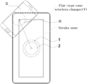
- FIG. 1 is a diagram illustrating an example of arrangement of a power transmitting coil and a power receiving coil in the related art of a flat-type case wireless charger, wherein a center of the power transmitting coil moves to a corner side within a large stroke zone towards a center point of the power receiving coil.
- FIG. 2 is a diagram illustrating an example of arrangement of a power transmitting coil and a power receiving coil, wherein a tray-type wireless charger is employed. According to the present invention, a center of the power transmitting coil moves to a center position of the power receiving coil only within a very small stroke zone.
- FIG. 3 is a flowchart illustrating overall operation of an autonomous wireless charging system based on power loss tracking according to the present invention.
- FIG. 4 is a flowchart illustrating control of a moving unit of an autonomous wireless charging system based on power loss tracking according to the present invention.
- FIG. 5 is a flowchart illustrating operation during charging after a moving unit of an autonomous wireless charging system based on power loss tracking is stopped according to the present invention.
- FIG. 6 is a flowchart illustrating determination of a moving direction by a moving unit of an autonomous wireless charging system based on power loss tracking according to the present invention.
- FIG. 7 is a diagram illustrating an example of a matrix of sensors to be selectively used when necessary, wherein the sensor matrix is used to determine a direction to a new position and inform the control unit when a position of a wireless device placed on a pad is displaced, in an autonomous wireless charging system based on power loss tracking according to the present invention.
- FIG. 8 is a diagram illustrating communication between a power transmitter and a power receiver; power transmission; an interoperational relationship set for movement of a transmitting coil; three main modules (a power unit, a moving unit, and a control unit) constituting the power transmitter; and an MCU (controller) positioned within the control unit.
- FIG. 9 is a comparison table illustrating the remarkable difference in effects when autonomously executing a wireless charging system using one power transmitting coil according to an embodiment of the present invention.
- FIG. 10 is a diagram illustrating an example of a structure for estimating power loss in the transmit/receive channel so as to describe a function for detecting a foreign object according to an embodiment of the present invention.
- FIG. 11 is a diagram illustrating an example in which a moving unit among internal configuration modules of an autonomous wireless charger T based on power loss tracking moves a center of a power transmitting coil to a center position of a power receiving coil of a smartphone according to an embodiment of the present invention.
- FIG. 12 is a diagram illustrating internal arrangement of main modules of an autonomous wireless charging system based on power loss tracking according to an embodiment of the present invention.
- FIG. 13 is a diagram illustrating a mechanism design and configuration of a moving unit in detail in a transparent manner, for example, an X-axis rack gear, a gear fixedly coupled to an X-axis rail, a power transmitting coil, a ferrite, and the like, in an autonomous wireless charging system based on power loss tracking according to an embodiment of the present invention.
- FIG. 14 is graphs illustrating distribution of power loss values and consistency of increase and decrease thereof, respectively, according to a distance between a power transmitting coil and a power receiving coil in an autonomous wireless charging system based on power loss tracking, as an embodiment of the present invention.
- FIG. 15 is a diagram illustrating an embodiment in which a combination of stationery and charger and a tray-type charger are used in the form of both a pad and a rotary stand, in an autonomous wireless charging system based on power loss tracking according to an embodiment of the present invention.
- FIG. 16 is a diagram illustrating an example of built-in type embodiments in furnitures such as office and conference room desks, sofas, and the like; treadmill infrastructure of an autonomous wireless charging system according to an embodiment of the present invention.
- FIG. 17 is a diagram illustrating built-in type embodiments provided on and inside a console, in an available space behind a mug cup holder of an autonomous wireless charging system based on power loss tracking according to an embodiment of the present invention.
- FIG. 18 is a diagram illustrating various types of embodiments, such as a charging pad for both a wireless rechargeable mouse and a smartphone, and a garage and a parking lot for charging electric vehicles, in an autonomous wireless charging system based on power loss tracking according to an embodiment of the present invention.
- an autonomous wireless charging system based on power loss tracking, wherein a tray-type case is employed; a controller sets a basic value or a threshold value on the basis of a power loss value generated in a process of detecting a foreign object by a power transmitter; a power transmitting coil is moved within a predetermined time in a direction of a sensed position through periodic monitoring of the power loss value so that a wireless device is autonomously charged; when a position of the wireless device is displaced, position tracking is performed again; and the power transmitting coil is moved only within a stroke zone that is positioned at a center point of the autonomous wireless charging system and that moves vertically and horizontally.
- FIG. 1 shows an example of arrangement of a power transmitting coil 2 and a power receiving coil R in the related art, wherein in order to track a position of a wireless device S placed on a flat-type case pad, the power transmitting coil 2 is moved to the corner of the pad towards the power receiving coil R by using a detection circuit board in a size similar to the area of the pad.
- This case causes the following several disadvantages: the presence of a dead space on the pad, a large moving unit of screw type moving by a relatively long distance, lack of durability, loud noise, operation of a number of components, and high production expense.
- FIG. 2 shows an example of arrangement of a power transmitting coil 2 and a power receiving coil R within a very small stroke zone of a tray-type wireless charger T instead of a large stroke zone that a flat-type case pad has. Therefore, it is economical because the moving distance is short and the design dimension of a motor or a mechanical part is reduced. In addition, the torque of a motor also has a margin and the noise caused by rotation of the motor is low because moving by a long distance rarely occurs. Further, a moving unit using an X-Y guide employing a slide bearing method also secures durability so that it can withstand quite strong vibration and impact. Unlike the related art, tracking the center position of the power receiving coil R on the basis of power loss tracking according to the present invention does not require a position tracking circuit board, and is thus relatively more economical.
- FIG. 3 shows the overall operation of an autonomous wireless charging system based on power loss tracking according to the present invention.
- a power transmitting coil 2 of a moving unit 4 moves to the center position of the system that is in a standby mode state at step S 302 .
- a power loss value is sensed through communication with a power unit 3 at step S 303 .
- a moving direction of the moving unit 4 is selected at step S 304 .
- the moving direction is calculated for an X axis and a Y axis each.
- the sensed value is stored at step S 305 , and the moving unit 4 is moved at step S 306 .
- step S 307 It is checked whether the sensed value is effective at step S 307 .
- the sensed data value when the sensed data value is effective, it means that the value is steadily increased or decreased.
- the moving direction of the moving unit 4 is determined on the basis of whether the value is effective.
- the moving unit 4 is stopped at step S 308 .
- the moving unit 4 is moved at step S 306 and the power loss value is sensed again to keep determining whether the value is effective.
- the moving unit 4 is stopped at step S 308 and the power loss value is sensed at step S 309 . It is identified whether there is a change in the sensed power loss value at step S 310 .
- the moving unit 4 is moved to the center position at step S 302 .
- the moving unit 4 goes into a stop state and the subsequent steps are repeated.
- FIG. 4 shows the movement (S 401 ) of moving unit 4 .
- the direction of the moving unit 4 is determined at step S 402 .
- the moving unit 4 is moved to the determined moving direction by a predetermined distance at step S 405 .
- the sensed value is stored and a virtual position value is updated at step S 406 .
- the moving direction is not determined, proceeding to a loop S 404 of selecting the direction of the moving unit 4 takes place.
- it is identified whether the moving direction is determined at step S 403 , and it is determined whether to move by a predetermined distance.
- the updating of the virtual position means moving by a predetermined distance to the virtual position of the moving unit 4 .
- the updating is necessary to prevent an overrun and return to the center position after moving is stopped.
- the virtual position is related to the stroke zone.
- the moving unit 4 has actually moved to remember the position of the boundary line that should not be crossed, namely, the range in which the moving unit is allowed to move, the virtual position is also updated.
- an error counter is initialized at step S 411 , moving to the moving direction by a predetermined distance is performed at step S 405 , and the remaining steps are repeated.
- the error counter is increased by one at step S 410 . It is identified whether the error counter is the maximum value at step 5412 . When the maximum value is reached, proceeding to a step S 413 of stopping the moving unit 4 takes place. Otherwise, moving towards the moving direction by a predetermined distance is performed at step S 405 and the remaining steps are repeated.
- FIG. 5 shows the operation (S 501 ) during charging after the moving unit 4 is stopped.
- the motor is stopped at step S 502 , the power loss value is sensed at step S 503 , and it is determined whether the sensed value is effective at step S 505 .
- full charge it is determined whether the sensed value is effective at step S 505 .
- the moving unit 4 is returned to its original position at step S 507 , updates the virtual position at step S 508 , and proceeds to a step S 509 of controlling the moving unit 4 .
- FIG. 6 shows the operation of selecting (S 601 ) the direction of the moving unit 4 .
- the moving direction of the moving unit 4 is identified at step S 602 . It is determined whether the identified moving direction is determined at step S 603 .
- a movement control process is performed.
- moving to the right by a predetermined distance is performed at step S 605 and the virtual position is updated at step S 606 .
- the power loss value is sensed again at step S 607 , and it is identified whether the sensed value is decreased at step S 608 .
- the decrease in the sensed value means that the power transmitting coil 2 of the moving unit 4 approaches to the center of the power receiving coil R of the wireless device S. Therefore, the right counter is increased at step S 609 , and the left counter is initialized at step S 610 . Then, it is identified whether the value of the right counter is a setting value at step S 611 . When the value of the right counter is the setting value, the right direction is selected at step S 612 and the moving direction of the moving unit 4 is identified again at step S 6012 . When the value of the right counter is not the setting value, the moving unit 4 is moved to the right by a predetermined distance at step S 605 , the virtual position is updated at step S 606 , and the remaining steps are repeated.
- the left counter is increased at step S 613
- the right counter is initialized at step S 614 , and it is determined whether the left counter has a setting value at step S 615 .
- the left counter has the setting value
- the left direction is selected at step S 615
- the moving direction of the moving unit 4 is identified at step S 602 .
- the moving unit 4 is moved to the right by a predetermined distance at step S 605 , the virtual position is updated at step S 606 , and the remaining steps are repeated.
- FIG. 7 shows an example of a matrix of 16 sensors 7 that are selectively used when necessary.
- the matrix of sensors 7 may be controlled in such a manner as to inform about the direction indicating which of four quadrants the smartphone is positioned on, in the case of displacement, and in such a manner as to track subdivided four quadrants depending on implementation.
- the sensor 7 various types of sensors may be used.
- the matrix of sensors 7 needs to have the sensors 7 arranged at positions that are integer multiples of 1 mm.
- the power transmitting coil 2 is moved to the final displacement position by moving by 12.5 mm on the X axis and by 22.5 mm on the Y axis from the center of the cell of the sensor 7 .
- the method of using the matrix of the sensors 7 is more efficient in calculating the direction when it is predicted that the sensor 7 becomes cheaper, smaller, and lighter.
- the upper figure of FIG. 8 shows an air-core transformer structure as follows.
- Wireless charging using a magnetic induction method has a weak connection between the primary coil 2 of the power transmitter T and the secondary coil R of the power receiver S.
- the magnetic flux at the primary coil is induced to the secondary coil.
- the induced magnetic flux generates electromotive force at the secondary coil, so that power is transmitted to the secondary coil.
- the autonomous wireless charging system (power transmitter T) based on power loss tracking is composed of three main modules, such as the power unit 3 , the moving unit 4 , and a control unit 5 .
- An MCU (controller 6 ) in the control unit 5 intensively manages system operation control and processes, such as reading the power loss value, recognizing and tracking the position, stopping and moving the power transmitting coil 2 up, down, left, right, and the like.
- the controller 6 precisely tracks the center position of the power receiving coil R of the power receiver S. Even when the position of the power receiver S is displaced, the controller 6 controls the power transmitting coil 2 of the moving unit 4 to move to that position.
- FIG. 9 is a table resulting from an analysis for an autonomous wireless charging system using one transmitting coil 2 .
- the system provides superior features and performances in terms of convenience, effective charging efficiency, freedom, cost effectiveness, and universality, compared to a system using one to three power transmitting coils in the related art.
- the addition of the moving unit 4 and the control unit 5 increases product production cost to some extent.
- one coil is used instead of two or three coils, a ferrite area is also reduced accordingly, and there is no need for expensive switching components required in the procedure of selecting one determined coil out of two or three coils given: these lead to great advantages in terms of cost and complexity.
- the power transmitter circuit T using the one power transmitting coil 2 is more stabilized than the product using two or three coils, so it is useful to reduce production cost in mass production.
- the power transmitter circuit T can be used for all smartphone (S) models without limitation, and always guarantees the optimum effective charging efficiency E max and simultaneously implements a true free-positioning autonomous wireless charger. Therefore, considering cost effectiveness, the power transmitter circuit T has more superiority than that of the existing product (technology) in terms of overall price competitiveness, product purchasing power, a variety of application fields, and the like.
- FIG. 10 is a diagram defining a power loss that is importantly used in the present invention.
- the power loss is defined as the difference between the transmitted power and the received power when the power transmitter T transmits power to the power receiver S.
- a ping occurs between the power transmitter T and the power receiver S.
- three packets for signal strength, identification, and configuration are transmitted to enter a negotiation step. After the negotiation, a calibration step is entered.
- the power transmitter T uses so-called linear interpolation to adjust a transmitted power value and a received power value, estimates the adjusted power values to calculates a power loss value, and compares the value with a threshold to determine whether an object on the pad is a foreign object.
- the power transmitter T When the object is identified as an object to be charged, the power transmitter T enters a power transmission step.
- the power transmitter T of the present invention that is, the controller 6 in the control unit 5 of the autonomous wireless charging system based on power loss tracking uses a power loss value in Equation below so as to track the center position of the power receiving coil R of the power receiver S.
- P loss P PT ⁇ P PR [Equation 1]
- the power loss is defined as the difference between the transmitted power P PT and the received power P PR .
- the controller 6 uses the value of P loss that is calculated by the power transmitter T, to control the movement of the power transmitting coil 2 into the direction in which the value of P loss decreases.
- P loss represents the power absorption of either a foreign object or an object to be charged.
- the received power P PR is determined as an average power consumed from the magnetic field in the power receiver S for a particular period of time.
- P In denotes the power value given at the input terminal of the power transmitter T.
- P PTloss denotes a power value consumed by an internal circuit (an inverter, a power transmitting coil, a resonant capacitor, a ferrite, and the like) of the power transmitter T.
- P Out denotes a power value given at an output terminal of the power receiver.
- P PRloss denotes a power value lost inside the power receiver S.
- the power transmitter T receives a received power packet from the power receiver S, calculates a power loss value P loss , and compares the value with a threshold value.
- a tray-type case is employed, and the moving unit 4 of the autonomous wireless charging system based on power loss tracking with high hardware and cost efficiency is positioned at the center of the system and moves the power transmitting coil 2 only within the stroke zone.
- the moving unit 4 of the autonomous wireless charging system based on power loss tracking with high hardware and cost efficiency is positioned at the center of the system and moves the power transmitting coil 2 only within the stroke zone.
- the controller 6 moves the power transmitting coil 2 again in a direction of the sensed position to continues the normal charging process for the power receiver S.
- the moving unit 4 in the autonomous wireless charging system T based on power loss tracking, among internal configuration modules, the moving unit 4 has an integrated structure of an X-axis rail 21 , a Y-axis rail 22 , and an X-axis motor 31 and a Y-axis motor 32 , which are provided inside the respective rails.
- the moving unit 4 equipped with a ferrite 1 and the power transmitting coil 2 moves.
- the moving unit 4 causes the power transmitting coil 2 to find and move to the center position of the power receiving coil R of the power receiver S.
- FIG. 12 shows an example in which the moving unit 4 is positioned in the center of the system T, according to an embodiment of the present invention.
- the moving unit 4 equipped with the ferrite 1 and the power transmitting coil 2 and composed of the X-axis rail 21 , the Y-axis rail 22 , and the like is provided at the center of the system so as to move in a shortest distance, to a place where the center position of the power receiver S is placed.
- a PCB for the control unit 5 and a PCB for the power transmission unit 3 are provided in available spaces A and B, respectively, whereby a problem of double stacking is resolved and the thickness of the wireless charging device is made slim.
- the power transmitting coil 2 with which the moving unit 4 is equipped may be implemented by extending the connection to the power transmission module with a flexible cable, such as a film cable.
- FIG. 13 shows the following.
- the moving unit 4 moving the coil is composed of a second slide bearing 42 , an X-axis rack gear 311 , the X-axis motor 31 , the Y-axis motor 32 , and a first slide bearing 41 , in the central part where the X-axis rail 21 and the Y-axis rail 22 cross along an X axis and a Y axis, respectively.
- the moving unit 4 is in conjunction with the control unit 5 .
- the controller 6 is in conjunction with the power transmission unit 3 and the moving unit 4 .
- the Y-axis rail 22 coupled to the second slide bearing 42 moves along the X-axis rail 21 .
- a slider coupled to the Y-axis rail 22 moves in the direction of the Y-axis rail 22 , thereby reaching the optimum position for wireless charging.
- the X-axis rail 21 is a device that is fixed across from one end to another end of a lower cover 2 . Accordingly, the Y-axis rail 22 moving in a manner that is fixed on the X-axis rail 21 moves the power transmitting coil 2 quickly to a particular position.
- the Y-axis rail 22 provided perpendicular to the X-axis rail 21 enables the power transmitting coil 2 coupled to the slider in a fixed manner, to move in the X-axis and the Y-axis direction and reach the optimum position for wireless charging.
- the Y-axis rail 22 is a rail provided with the following: a first through-hole formed to surround the X-axis motor 31 therein; and a second through-hole formed to surround the Y-axis motor 32 provided perpendicular to the X-axis motor 31 so that the Y-axis motor 32 is not visible from the outside.
- the X-axis motor 31 and the Y-axis motor 32 may be coupled to coupling holes formed in the Y-axis rail 22 .
- an area exposed above the coupling hole is the same as an area exposed below the coupling hole.
- the area exposed above the coupling hole is a space between the slider and the Y-axis rail 22 and is provided in such a manner not to obstruct the slider in moving along the Y axis.
- the area exposed below the coupling hole is a space between the Y-axis rail 22 and the X-axis rail 21 and is provided in such a manner not to obstruct the Y-axis rail 22 in moving along the X axis.
- the present invention may achieve removal of a dead space and stable movement (gentle movement, and removal of noise) by using a specialized structure in which a driving part (a driving motor, and a rack and pinion) is placed between a guide rail and a slider.
- a driving part a driving motor, and a rack and pinion
- the X-axis rack gear 311 is fixed on an upper side of the X-axis rail 21 and is placed to engage with an X-axis pinion gear 313 of the X-axis motor 31 .
- the second slide bearing 42 is positioned on each of opposite sides of the X-axis rail 21 .
- the X-axis motor 31 and the Y-axis motor 32 are inserted into the through-holes connecting the Y-axis rail 22 fixing the position of the X-axis motor 31 and the X-axis rail 21 .
- the Y-axis motor 32 is inserted into the through-hole 320 and fixed to the coupling hole formed on the Y-axis rail 22 .
- a bottom portion of the first slide bearing 41 that is formed in an E shape is coupled to each of the opposite end portions of the Y-axis rail 22 .
- the opposite sides of the Y-axis rail 22 are bent in the shape of stairs and the bent portions are inserted into the bottom portions of the first slide bearing 41 , respectively.
- a Y-axis rack gear 321 of the Y-axis motor 32 and a Y-axis pinion gear 323 that rotates by being engaged therewith are coupled.
- the slider is coupled to the upper portion of the “E”-shaped form so that the slider moves to any position along the X axis.
- the assembled X-axis rail 21 and Y-axis rail 22 are inserted into the lower cover, and only the X-axis rail 21 is fixed to the inner surface of the lower cover.
- the X-axis rail 21 does not move, but the Y-axis rail 22 above the X-axis rail 21 moves in the X-axis direction. After the Y-axis rail 22 moves to any position in the X-axis direction, the slider moves to any position in the Y-axis direction.
- the control unit 5 drives the moving unit 4 in the direction in which the power loss value decreases, so that the center position of the power transmitting coil 2 is moved to the center position of the power receiving coil R.
- the power loss value needs to have a consistent increase and decrease characteristics so that the moving unit 4 moves for aligning the center of the power transmitting coil 2 with the center of the power receiving coil R by only using the change in the power loss value without using a position detection circuit board.
- it is determined that the position of the power receiving coil R is coordinates (0, 0).
- FIG. 14 ( a ) shows the distribution of power loss values according to the measurement direction and position. It is shown that as the distance between the power transmitting coil 2 and the power receiving coil R increases, the loss value continuously increases.
- FIG. 14 ( b ) is a graph of power loss values measured for rectilinear trajectories in nine directions. It is a diagram that more clearly illustrates whether an increase in the loss value shows consistent behavior.
- the present invention may be applied not only to a tray-type case that limits the mounting position of the wireless device S, but also to a number of methods in which the controller 6 moves the mounting position to various objects to be charged (a wireless rechargeable smartphone, a wireless rechargeable vehicle, a wireless rechargeable mouse, a wireless rechargeable receive device, and the like) as show in FIGS. 15 to 18 through the autonomous wireless charging system based on power loss tracking.
- a wireless rechargeable smartphone a wireless rechargeable vehicle, a wireless rechargeable mouse, a wireless rechargeable receive device, and the like
- the present invention may be applied to any one of the following: a combination of stationery and autonomous wireless charger (a), (b), and a tray-type autonomous wireless charger T (c).
- a combination of stationery and autonomous wireless charging application product (a), (b) a module for the moving unit 4 is placed at the bottom of the charging pad, and PCBs for a control module and a power transmitting module are placed at the bottom of a stationery tray where a pen, or the like is positioned.
- the present invention may be applied to any one among furniture (a), (b), (c), such as an office and conference room desk, a sofa, and a treadmill (d), in a built-in type. If the system of the present invention is embedded in a building or furniture infrastructure, it creates excellent application points for a smart office and smart furniture that always provide the optimum effective charging efficiency as well as decisive convenience.
- the present invention may be applied to either certain positions on and inside a right front console of the driver's seat or an available space behind a mug cup holder (a), (c), and (d), and a front console in the front of a vehicle (b) where the user's hand and view are easily reached, in the form of a horizontal storage type, an slanted stand type, a laterally standing type, and a pocket insertion type.
- a front console in the front of a vehicle (b) where the user's hand and view are easily reached, in the form of a horizontal storage type, an slanted stand type, a laterally standing type, and a pocket insertion type.
- the system of the present invention is embedded in infrastructure of various vehicles (sedans, SUVs, trucks, motorcycles, and the like) that are susceptible to shaking, it creates excellent application points for smart vehicles that always provide the optimum effective charging efficiency as well as decisive convenience.
- the present invention may be applied to any one among a charging pad (a) for both a wireless rechargeable gaming mouse and a smartphone, and a garage and a parking lot using an overground pad (b) or a underground pad (c) for charging electric vehicles. Since a wireless charging system for electric vehicles can use the same method as wireless charging for smartphones S, excellent expandability is provided. In addition, even if the driver is unable to see below during parking, even if the driver does not align the wheels with the parking line exactly, even if there is no parking stopper, the optimum charging is provided even though the driver parks roughly.
- the power transmitting coil 2 installed on or under the ground is moved within the stroke zone along the X-axis rail 21 and the Y-axis rail 22 of the present invention so that the power transmitting coil 2 and the power receiving coil R are positioned on the coaxial line, whereby hardware and cost efficiency of a charging station increase, such as reduction in hardware cost, power saving, and the like.
- the power transmitting coil 2 with which the moving unit 4 is equipped is implemented by extending the connection to the power transmission module with a flexible cable, such as a film cable.
- a flexible cable such as a film cable.
- the ferrite 1 may be manufactured in an engraved shape surrounding the power transmitting coil 2 .
- U 1 , U 2 USB & power terminal
- V 1 Storage and charging part
- V 2 Cup holder
- V 3 Door and charging part
Landscapes
- Engineering & Computer Science (AREA)
- Power Engineering (AREA)
- Computer Networks & Wireless Communication (AREA)
- Transportation (AREA)
- Mechanical Engineering (AREA)
- Charge And Discharge Circuits For Batteries Or The Like (AREA)
Applications Claiming Priority (4)
| Application Number | Priority Date | Filing Date | Title |
|---|---|---|---|
| KR20170173343 | 2017-12-15 | ||
| KR1020180162963A KR102081413B1 (ko) | 2017-12-15 | 2018-12-17 | 전력손실 추적 기반의 자율 무선충전 시스템 및 방법 |
| PCT/KR2018/015997 WO2020130162A1 (fr) | 2017-12-15 | 2018-12-17 | Système de charge sans fil autonome et procédé basé sur un suivi de perte de puissance |
| KR10-2018-0162963 | 2018-12-17 |
Publications (2)
| Publication Number | Publication Date |
|---|---|
| US20210218289A1 US20210218289A1 (en) | 2021-07-15 |
| US11894697B2 true US11894697B2 (en) | 2024-02-06 |
Family
ID=67065292
Family Applications (1)
| Application Number | Title | Priority Date | Filing Date |
|---|---|---|---|
| US17/059,432 Active 2040-09-26 US11894697B2 (en) | 2017-12-15 | 2018-12-17 | Autonomous wireless charging system and method based on power loss tracking |
Country Status (3)
| Country | Link |
|---|---|
| US (1) | US11894697B2 (fr) |
| KR (1) | KR102081413B1 (fr) |
| WO (1) | WO2020130162A1 (fr) |
Families Citing this family (15)
| Publication number | Priority date | Publication date | Assignee | Title |
|---|---|---|---|---|
| CN112152325B (zh) * | 2019-06-28 | 2023-06-20 | 北京小米移动软件有限公司 | 线圈位置调整方法、装置和存储介质 |
| KR102798351B1 (ko) * | 2020-04-28 | 2025-04-22 | 삼성전자주식회사 | 무선 전력 전송 장치 및 그 제어 방법 |
| CN112531917B (zh) * | 2020-11-23 | 2022-12-09 | 歌尔光学科技有限公司 | 一种无线充电接收装置和一种电子设备 |
| JP7503001B2 (ja) * | 2021-01-12 | 2024-06-19 | 株式会社日立エルジーデータストレージ | 送電装置、受電装置、およびそれらを備えた送受電システム |
| CN112865344A (zh) * | 2021-03-25 | 2021-05-28 | Tcl通力电子(惠州)有限公司 | 一种无线充电设备及充电方法 |
| CN114825653A (zh) * | 2021-06-21 | 2022-07-29 | 长城汽车股份有限公司 | 一种无线充电控制方法、控制装置以及车辆 |
| KR102672326B1 (ko) | 2021-07-29 | 2024-06-05 | 한국전자통신연구원 | 무선 충전 시스템에서 영상 처리 기반 이물질 탐지 방법 및 이를 수행하는 장치 |
| CN113675955A (zh) * | 2021-08-13 | 2021-11-19 | 上海钧正网络科技有限公司 | 一种无线充电装置、方法、设备及存储介质 |
| CN114465365B (zh) * | 2022-02-22 | 2025-03-25 | Oppo广东移动通信有限公司 | 无线充电座及其控制方法 |
| US20240429753A1 (en) * | 2023-06-20 | 2024-12-26 | ohSnap, Inc. | Intermediate Receiver of Wireless Power Transfer |
| CN117197740B (zh) * | 2023-09-11 | 2026-03-31 | 广西电网有限责任公司电力科学研究院 | 无线充电区域的异物识别方法及系统 |
| KR20250171188A (ko) | 2024-05-29 | 2025-12-08 | 경문건 | 운전자 무개입 급전 패드 자동 얼라이닝 기능을 이용한 무선 충전 시스템 |
| KR20250176565A (ko) | 2024-06-12 | 2025-12-19 | 경문건 | 전기차 충전 코일의 정위치 추적과 포지션 얼라이닝이 가능한 이동식 무선 충전 시스템 |
| CN118763817B (zh) * | 2024-06-13 | 2025-03-04 | 南京邮电大学 | 一种具有空间占用且充电成本受限的无线充电调度方法 |
| TWI884100B (zh) * | 2024-10-21 | 2025-05-11 | 國立虎尾科技大學 | 異物位置偵測裝置及其偵測方法 |
Citations (36)
| Publication number | Priority date | Publication date | Assignee | Title |
|---|---|---|---|---|
| KR100841135B1 (ko) | 2005-10-31 | 2008-06-24 | 도꾜 코일 엔지니어링 가부시끼가이샤 | 솔라식 휴대 충전기 |
| KR20080081480A (ko) | 2007-03-05 | 2008-09-10 | 엘에스전선 주식회사 | 복수의 코일 패드를 구비한 무 접점 충전기 및 이를 구비한배터리 충전 세트 |
| KR20110034773A (ko) | 2009-09-29 | 2011-04-06 | 삼성전자주식회사 | 유도성 결합 방식을 이용한 무선 충전기 |
| KR20120014878A (ko) | 2010-08-10 | 2012-02-20 | 김영성 | 무접점 충전기용 코일 및 이 코일을 제조하기 위한 권선 용구 |
| KR20120099571A (ko) | 2009-06-25 | 2012-09-11 | 다나신덴기가부시키가이샤 | 2차원 이동 기구를 탑재한 무접점 충전기 |
| KR20120117262A (ko) | 2011-04-15 | 2012-10-24 | 현대자동차주식회사 | 코일의 위치 정렬이 가능한 차량용 무선전력전송기 |
| CN102882243A (zh) | 2011-06-21 | 2013-01-16 | 德利信电机株式会社 | 线圈移动型无接点充电器 |
| KR101250290B1 (ko) | 2012-03-06 | 2013-04-03 | 주식회사 삼광 | 코일 이동형 무선 충전기 |
| KR20140019955A (ko) | 2012-08-07 | 2014-02-18 | (주)디팜스 | 무선충전기용 tx 3코일 덮개 |
| KR20140067101A (ko) | 2011-09-09 | 2014-06-03 | 위트리시티 코포레이션 | 무선 에너지 전송 시스템에서의 이물질 검출 |
| US8754608B2 (en) * | 2011-02-07 | 2014-06-17 | Pantech Co., Ltd. | System and method for charging electronic device by communicating with and moving the electronic device |
| US20140176057A1 (en) * | 2012-12-21 | 2014-06-26 | Ford Global Technologies, Llc | System of securing a wide-range of devices during wireless charging |
| KR20140085591A (ko) | 2011-11-04 | 2014-07-07 | 위트리시티 코포레이션 | 무선 에너지 전송 모델링 툴 |
| US20140253030A1 (en) * | 2013-03-06 | 2014-09-11 | Hanshinkijeon Co., Ltd. | Automatically position adjustable wireless charger and charging method using the same |
| US8981719B2 (en) | 2010-04-01 | 2015-03-17 | Sanyo Electric Co., Ltd. | Battery pack charger |
| US9018900B2 (en) | 2011-07-28 | 2015-04-28 | Sanyo Electric Co., Ltd. | Battery pack, battery powered device, and contactless charging method |
| KR20150054887A (ko) | 2012-09-11 | 2015-05-20 | 퀄컴 인코포레이티드 | 무선 전력 전송 시스템 코일 어레인지먼트들 및 동작 방법 |
| US9312711B2 (en) | 2007-12-18 | 2016-04-12 | Panasonic Corporation | Battery charger cradle |
| US20160261135A1 (en) * | 2013-10-21 | 2016-09-08 | Panasonic Intellectual Property Management Co., Ltd. | Mobile terminal charging device and automobile using same |
| KR20170008800A (ko) | 2014-05-15 | 2017-01-24 | 퀄컴 인코포레이티드 | 유도 열 감지에 기초한 외래 오브젝트 검출 루프를 위한 시스템들, 방법들 및 장치 |
| KR101701054B1 (ko) | 2015-06-12 | 2017-01-31 | 삼성전기주식회사 | 차량용 무선 충전 장치 |
| KR20170019629A (ko) | 2015-08-12 | 2017-02-22 | 현대자동차주식회사 | 무선 전력 송신기의 제어 방법과 이를 적용한 무선 충전 시스템 |
| US9671884B2 (en) * | 2013-12-20 | 2017-06-06 | Hyundai Motor Company | Apparatus and method for operating multimedia apparatus performing wireless charging for portable apparatus |
| US9819214B2 (en) * | 2013-12-13 | 2017-11-14 | Lg Electronics Inc. | Wireless charger for mobile terminal |
| KR20170140734A (ko) | 2016-06-13 | 2017-12-21 | 엘지이노텍 주식회사 | 이물질 검출 방법 및 그를 위한 장치 및 시스템 |
| US9853484B2 (en) | 2013-05-31 | 2017-12-26 | Panasonic Intellectual Property Management Co., Ltd. | Mobile terminal charging device, and vehicle using same |
| US20180287413A1 (en) * | 2015-10-07 | 2018-10-04 | Lg Innotek Co., Ltd. | Wireless charging device alignment guiding method and device and system for same |
| US10158243B2 (en) * | 2015-09-22 | 2018-12-18 | Hyundai Motor Company | Wireless charger having automatic alignment function and method thereof |
| US20190190324A1 (en) * | 2016-09-21 | 2019-06-20 | Apple Inc. | Detection of Object Location and Orientation on a Wireless Charge Mat |
| US10447064B2 (en) * | 2017-06-28 | 2019-10-15 | Kinpo Electronics, Inc. | Wireless charging system and wireless charging method |
| US20190386522A1 (en) * | 2018-06-15 | 2019-12-19 | Lg Innotek Co., Ltd. | Method and apparatus for controlling wireless power transmission |
| US10566822B2 (en) * | 2017-07-28 | 2020-02-18 | Toyota Motor Engineering & Manufacturing North America, Inc. | Providing a movable charging coil |
| US20200083754A1 (en) * | 2018-09-07 | 2020-03-12 | Google Llc | Controlling wireless charging |
| US20200287425A1 (en) * | 2017-03-07 | 2020-09-10 | Powermat Technologies Ltd. | System for wireless power charging |
| US11005309B2 (en) * | 2018-01-26 | 2021-05-11 | Wbtec, Llc | Charging apparatus with locator |
| US20230268780A1 (en) * | 2020-07-23 | 2023-08-24 | Electdis Ab | A testing device for testing a wireless power device, and an associated method |
Family Cites Families (4)
| Publication number | Priority date | Publication date | Assignee | Title |
|---|---|---|---|---|
| KR101963261B1 (ko) * | 2013-03-22 | 2019-03-28 | 삼성전기주식회사 | 무선 충전 장치 |
| US20160064943A1 (en) * | 2014-08-28 | 2016-03-03 | Konkuk University Industrial Cooperation Corp. | Controlling method and system of power transmission system |
| KR20160028262A (ko) * | 2014-09-03 | 2016-03-11 | 에스엘 주식회사 | 차량용 콘솔 어셈블리 |
| KR102882243B1 (ko) | 2022-01-05 | 2025-11-06 | 엘지전자 주식회사 | 의류처리장치 |
-
2018
- 2018-12-17 WO PCT/KR2018/015997 patent/WO2020130162A1/fr not_active Ceased
- 2018-12-17 KR KR1020180162963A patent/KR102081413B1/ko active Active
- 2018-12-17 US US17/059,432 patent/US11894697B2/en active Active
Patent Citations (37)
| Publication number | Priority date | Publication date | Assignee | Title |
|---|---|---|---|---|
| KR100841135B1 (ko) | 2005-10-31 | 2008-06-24 | 도꾜 코일 엔지니어링 가부시끼가이샤 | 솔라식 휴대 충전기 |
| KR20080081480A (ko) | 2007-03-05 | 2008-09-10 | 엘에스전선 주식회사 | 복수의 코일 패드를 구비한 무 접점 충전기 및 이를 구비한배터리 충전 세트 |
| US9312711B2 (en) | 2007-12-18 | 2016-04-12 | Panasonic Corporation | Battery charger cradle |
| US8907619B2 (en) * | 2009-06-25 | 2014-12-09 | Tanashin Denki Co., Ltd. | Wireless charger installed with a two-dimensional moving mechanism |
| KR20120099571A (ko) | 2009-06-25 | 2012-09-11 | 다나신덴기가부시키가이샤 | 2차원 이동 기구를 탑재한 무접점 충전기 |
| KR20110034773A (ko) | 2009-09-29 | 2011-04-06 | 삼성전자주식회사 | 유도성 결합 방식을 이용한 무선 충전기 |
| US8981719B2 (en) | 2010-04-01 | 2015-03-17 | Sanyo Electric Co., Ltd. | Battery pack charger |
| KR20120014878A (ko) | 2010-08-10 | 2012-02-20 | 김영성 | 무접점 충전기용 코일 및 이 코일을 제조하기 위한 권선 용구 |
| US8754608B2 (en) * | 2011-02-07 | 2014-06-17 | Pantech Co., Ltd. | System and method for charging electronic device by communicating with and moving the electronic device |
| KR20120117262A (ko) | 2011-04-15 | 2012-10-24 | 현대자동차주식회사 | 코일의 위치 정렬이 가능한 차량용 무선전력전송기 |
| CN102882243A (zh) | 2011-06-21 | 2013-01-16 | 德利信电机株式会社 | 线圈移动型无接点充电器 |
| US9018900B2 (en) | 2011-07-28 | 2015-04-28 | Sanyo Electric Co., Ltd. | Battery pack, battery powered device, and contactless charging method |
| KR20140067101A (ko) | 2011-09-09 | 2014-06-03 | 위트리시티 코포레이션 | 무선 에너지 전송 시스템에서의 이물질 검출 |
| KR20140085591A (ko) | 2011-11-04 | 2014-07-07 | 위트리시티 코포레이션 | 무선 에너지 전송 모델링 툴 |
| KR101250290B1 (ko) | 2012-03-06 | 2013-04-03 | 주식회사 삼광 | 코일 이동형 무선 충전기 |
| KR20140019955A (ko) | 2012-08-07 | 2014-02-18 | (주)디팜스 | 무선충전기용 tx 3코일 덮개 |
| KR20150054887A (ko) | 2012-09-11 | 2015-05-20 | 퀄컴 인코포레이티드 | 무선 전력 전송 시스템 코일 어레인지먼트들 및 동작 방법 |
| US20140176057A1 (en) * | 2012-12-21 | 2014-06-26 | Ford Global Technologies, Llc | System of securing a wide-range of devices during wireless charging |
| US20140253030A1 (en) * | 2013-03-06 | 2014-09-11 | Hanshinkijeon Co., Ltd. | Automatically position adjustable wireless charger and charging method using the same |
| US9853484B2 (en) | 2013-05-31 | 2017-12-26 | Panasonic Intellectual Property Management Co., Ltd. | Mobile terminal charging device, and vehicle using same |
| US20160261135A1 (en) * | 2013-10-21 | 2016-09-08 | Panasonic Intellectual Property Management Co., Ltd. | Mobile terminal charging device and automobile using same |
| US9819214B2 (en) * | 2013-12-13 | 2017-11-14 | Lg Electronics Inc. | Wireless charger for mobile terminal |
| US9671884B2 (en) * | 2013-12-20 | 2017-06-06 | Hyundai Motor Company | Apparatus and method for operating multimedia apparatus performing wireless charging for portable apparatus |
| KR20170008800A (ko) | 2014-05-15 | 2017-01-24 | 퀄컴 인코포레이티드 | 유도 열 감지에 기초한 외래 오브젝트 검출 루프를 위한 시스템들, 방법들 및 장치 |
| KR101701054B1 (ko) | 2015-06-12 | 2017-01-31 | 삼성전기주식회사 | 차량용 무선 충전 장치 |
| KR20170019629A (ko) | 2015-08-12 | 2017-02-22 | 현대자동차주식회사 | 무선 전력 송신기의 제어 방법과 이를 적용한 무선 충전 시스템 |
| US10158243B2 (en) * | 2015-09-22 | 2018-12-18 | Hyundai Motor Company | Wireless charger having automatic alignment function and method thereof |
| US20180287413A1 (en) * | 2015-10-07 | 2018-10-04 | Lg Innotek Co., Ltd. | Wireless charging device alignment guiding method and device and system for same |
| KR20170140734A (ko) | 2016-06-13 | 2017-12-21 | 엘지이노텍 주식회사 | 이물질 검출 방법 및 그를 위한 장치 및 시스템 |
| US20190190324A1 (en) * | 2016-09-21 | 2019-06-20 | Apple Inc. | Detection of Object Location and Orientation on a Wireless Charge Mat |
| US20200287425A1 (en) * | 2017-03-07 | 2020-09-10 | Powermat Technologies Ltd. | System for wireless power charging |
| US10447064B2 (en) * | 2017-06-28 | 2019-10-15 | Kinpo Electronics, Inc. | Wireless charging system and wireless charging method |
| US10566822B2 (en) * | 2017-07-28 | 2020-02-18 | Toyota Motor Engineering & Manufacturing North America, Inc. | Providing a movable charging coil |
| US11005309B2 (en) * | 2018-01-26 | 2021-05-11 | Wbtec, Llc | Charging apparatus with locator |
| US20190386522A1 (en) * | 2018-06-15 | 2019-12-19 | Lg Innotek Co., Ltd. | Method and apparatus for controlling wireless power transmission |
| US20200083754A1 (en) * | 2018-09-07 | 2020-03-12 | Google Llc | Controlling wireless charging |
| US20230268780A1 (en) * | 2020-07-23 | 2023-08-24 | Electdis Ab | A testing device for testing a wireless power device, and an associated method |
Also Published As
| Publication number | Publication date |
|---|---|
| KR102081413B1 (ko) | 2020-02-25 |
| US20210218289A1 (en) | 2021-07-15 |
| WO2020130162A1 (fr) | 2020-06-25 |
| KR20190072484A (ko) | 2019-06-25 |
Similar Documents
| Publication | Publication Date | Title |
|---|---|---|
| US11894697B2 (en) | Autonomous wireless charging system and method based on power loss tracking | |
| US10090713B2 (en) | Multiple coils for wireless power | |
| US10576833B2 (en) | Vehicle charger positioning method and charger assembly | |
| US8659580B2 (en) | Electromagnetic pen without a battery | |
| US8878393B2 (en) | Wireless power transfer for vehicles | |
| US20210320532A1 (en) | Improved wireless power transfer | |
| US12206257B2 (en) | Surface mountable wireless power transmitter for transmission at extended range | |
| US20160072334A1 (en) | Wireless charging device and method thereof | |
| KR102097497B1 (ko) | 이동단말기 무선충전기 | |
| EP3793060B1 (fr) | Système et dispositif d'alimentation sans fil | |
| CN105515224A (zh) | 为电动车充电的移动充电装置及其充电系统 | |
| JP2005110412A (ja) | 電力供給システム | |
| KR20120140611A (ko) | 코일 이동형 무접점 충전기 | |
| WO2010093721A1 (fr) | Système, appareil et procédé pour un transfert d'énergie dans des lieux publics | |
| US20250125656A1 (en) | Wireless Power Transmitter With Removable Magnetic Connector Panel | |
| CN109660027A (zh) | 一种融合红外导航及磁导航的机器人自动充电系统及方法 | |
| CN109742827A (zh) | 无线充电装置及无线充电装置的控制方法 | |
| US20240348095A1 (en) | Wireless Power Transmitters For Transmitting Power At Extended Separation Distances With Magnetic Connectors | |
| KR102300573B1 (ko) | 틸트 기능을 이용하여 다수의 사용자 단말을 동시에 충전하는 무선 충전 장치 | |
| US20170025905A1 (en) | Method of automatic charging | |
| KR20190092203A (ko) | 하드웨어 및 비용 효율이 높은 자율 무선충전 장치 | |
| CN105811545A (zh) | 用于电子设备的充电底座、充电系统和充电方法 | |
| KR102228389B1 (ko) | 무선 전력 송신기의 각도 제어 방법 및 장치 | |
| CN114696478A (zh) | 一种无线充电对准方法、装置、存储介质及无线充电座 | |
| CN210041385U (zh) | 无线充电底座 |
Legal Events
| Date | Code | Title | Description |
|---|---|---|---|
| AS | Assignment |
Owner name: WONCOMM CO., LTD., KOREA, REPUBLIC OF Free format text: ASSIGNMENT OF ASSIGNORS INTEREST;ASSIGNOR:KYEONG, MUN GEON;REEL/FRAME:054483/0160 Effective date: 20201127 |
|
| FEPP | Fee payment procedure |
Free format text: ENTITY STATUS SET TO UNDISCOUNTED (ORIGINAL EVENT CODE: BIG.); ENTITY STATUS OF PATENT OWNER: SMALL ENTITY |
|
| FEPP | Fee payment procedure |
Free format text: ENTITY STATUS SET TO SMALL (ORIGINAL EVENT CODE: SMAL); ENTITY STATUS OF PATENT OWNER: SMALL ENTITY |
|
| STPP | Information on status: patent application and granting procedure in general |
Free format text: APPLICATION DISPATCHED FROM PREEXAM, NOT YET DOCKETED |
|
| STPP | Information on status: patent application and granting procedure in general |
Free format text: DOCKETED NEW CASE - READY FOR EXAMINATION |
|
| STPP | Information on status: patent application and granting procedure in general |
Free format text: NON FINAL ACTION MAILED |
|
| STPP | Information on status: patent application and granting procedure in general |
Free format text: RESPONSE TO NON-FINAL OFFICE ACTION ENTERED AND FORWARDED TO EXAMINER |
|
| STPP | Information on status: patent application and granting procedure in general |
Free format text: NOTICE OF ALLOWANCE MAILED -- APPLICATION RECEIVED IN OFFICE OF PUBLICATIONS |
|
| STPP | Information on status: patent application and granting procedure in general |
Free format text: PUBLICATIONS -- ISSUE FEE PAYMENT RECEIVED |
|
| STPP | Information on status: patent application and granting procedure in general |
Free format text: PUBLICATIONS -- ISSUE FEE PAYMENT VERIFIED |
|
| STCF | Information on status: patent grant |
Free format text: PATENTED CASE |