US12000746B2 - Windshield sensing device - Google Patents
Windshield sensing device Download PDFInfo
- Publication number
- US12000746B2 US12000746B2 US17/212,602 US202117212602A US12000746B2 US 12000746 B2 US12000746 B2 US 12000746B2 US 202117212602 A US202117212602 A US 202117212602A US 12000746 B2 US12000746 B2 US 12000746B2
- Authority
- US
- United States
- Prior art keywords
- attachment member
- transducer
- sensing device
- sensing
- pressing device
- Prior art date
- Legal status (The legal status is an assumption and is not a legal conclusion. Google has not performed a legal analysis and makes no representation as to the accuracy of the status listed.)
- Active, expires
Links
Images




Classifications
-
- B—PERFORMING OPERATIONS; TRANSPORTING
- B60—VEHICLES IN GENERAL
- B60R—VEHICLES, VEHICLE FITTINGS, OR VEHICLE PARTS, NOT OTHERWISE PROVIDED FOR
- B60R11/00—Arrangements for holding or mounting articles, not otherwise provided for
-
- G—PHYSICS
- G01—MEASURING; TESTING
- G01L—MEASURING FORCE, STRESS, TORQUE, WORK, MECHANICAL POWER, MECHANICAL EFFICIENCY, OR FLUID PRESSURE
- G01L5/00—Apparatus for, or methods of, measuring force, work, mechanical power, or torque, specially adapted for specific purposes
- G01L5/0028—Force sensors associated with force applying means
- G01L5/0038—Force sensors associated with force applying means applying a pushing force
-
- B—PERFORMING OPERATIONS; TRANSPORTING
- B60—VEHICLES IN GENERAL
- B60R—VEHICLES, VEHICLE FITTINGS, OR VEHICLE PARTS, NOT OTHERWISE PROVIDED FOR
- B60R11/00—Arrangements for holding or mounting articles, not otherwise provided for
- B60R11/04—Mounting of cameras operative during drive; Arrangement of controls thereof relative to the vehicle
-
- B—PERFORMING OPERATIONS; TRANSPORTING
- B60—VEHICLES IN GENERAL
- B60R—VEHICLES, VEHICLE FITTINGS, OR VEHICLE PARTS, NOT OTHERWISE PROVIDED FOR
- B60R11/00—Arrangements for holding or mounting articles, not otherwise provided for
- B60R2011/0001—Arrangements for holding or mounting articles, not otherwise provided for characterised by position
- B60R2011/0003—Arrangements for holding or mounting articles, not otherwise provided for characterised by position inside the vehicle
- B60R2011/0026—Windows, e.g. windscreen
-
- B—PERFORMING OPERATIONS; TRANSPORTING
- B60—VEHICLES IN GENERAL
- B60S—SERVICING, CLEANING, REPAIRING, SUPPORTING, LIFTING, OR MANOEUVRING OF VEHICLES, NOT OTHERWISE PROVIDED FOR
- B60S1/00—Cleaning of vehicles
- B60S1/02—Cleaning windscreens, windows or optical devices
- B60S1/04—Wipers or the like, e.g. scrapers
- B60S1/06—Wipers or the like, e.g. scrapers characterised by the drive
- B60S1/08—Wipers or the like, e.g. scrapers characterised by the drive electrically driven
- B60S1/0818—Wipers or the like, e.g. scrapers characterised by the drive electrically driven including control systems responsive to external conditions, e.g. by detection of moisture, dirt or the like
- B60S1/0822—Wipers or the like, e.g. scrapers characterised by the drive electrically driven including control systems responsive to external conditions, e.g. by detection of moisture, dirt or the like characterized by the arrangement or type of detection means
- B60S1/0874—Wipers or the like, e.g. scrapers characterised by the drive electrically driven including control systems responsive to external conditions, e.g. by detection of moisture, dirt or the like characterized by the arrangement or type of detection means characterized by the position of the sensor on the windshield
- B60S1/0881—Wipers or the like, e.g. scrapers characterised by the drive electrically driven including control systems responsive to external conditions, e.g. by detection of moisture, dirt or the like characterized by the arrangement or type of detection means characterized by the position of the sensor on the windshield characterized by the attachment means on the windshield
Definitions
- the present invention relates to a sensing device and, more particularly, to a windshield sensing device.
- Temperature sensors, humidity sensors, optical sensors or a combination thereof are known to be used in windshield sensing devices for the purpose of automatically adapting the heating, ventilation, and air conditioning (so called HVAC) or for automatically switching on the wiper.
- a windshield temperature sensing device is commonly used for preventing fogging conditions.
- Windshield mounted temperature and/or humidity sensors can further be combined with light sensors or solar sensors.
- the sensor of the sensing device has to be kept in constant contact with the surface of the windshield surface during the whole lifetime of the vehicle, and thus withstand mechanical shock and vibration.
- FIGS. 9 a and 9 b A conventional temperature sensing device 1 is shown in FIGS. 9 a and 9 b .
- a thermistor 10 can be soldered on a flexible polyimide film 12 such that one end 14 of the polyimide film 12 is then soldered to a printed circuit board (PCB) 16 and another end 18 , on which the thermistor 10 is welded, is maintained on the windshield surface 20 .
- the end 18 provided with the thermistor 10 is usually pressed against the windshield surface 22 by foam elements 24 , 26 , such as thermal foam, arranged on either side of the thermistor 10 .
- foam elements 24 , 26 such as thermal foam
- the foam used for fixing the polyimide film with the thermistor on the windshield is subject to aging, degradation and/or mechanical stress. Furthermore, the soldering of the thermistor on the polyimide film, the soldering of the sensing device to the PCB, and the soldering of the connector pin contact to the PCB complicate the soldering process by requiring successive steps.
- a sensing device for a windshield includes an attachment member attachable to a surface of the windshield and a sensing element having a transducer.
- the attachment member has a pressing device. The pressing device applies a pressure on or over the transducer when the attachment member is attached to the surface and presses the transducer against the surface.
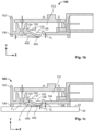
- FIG. 1 a is a sectional side view of a sensing device according to a first embodiment attached to a surface of a windshield;
- FIG. 1 b is a sectional side view of the sensing device not attached to the surface
- FIG. 1 c is a sectional side view of the sensing device attached to the surface
- FIG. 2 is a sectional top view of a sensing element of the sensing device
- FIG. 3 is a perspective view of a sensing device according to a second embodiment
- FIG. 4 is a detail perspective view of the sensing device of FIG. 3 ;
- FIG. 5 is an exploded perspective view of the sensing device of FIG. 3 ;
- FIG. 6 is a perspective view of a sensing device according to a variant of the second embodiment
- FIG. 7 is a sectional perspective view of a sensing device according to a third embodiment.
- FIG. 8 is a detail sectional perspective view of the sensing device of FIG. 7 ;
- FIG. 9 a is a sectional side view of a sensing device of the prior art not attached to a surface of a windshield.
- FIG. 9 b is a sectional side view of the sensing device the prior art attached to the surface of the windshield.
- FIGS. 1 a - 1 c show a cross-sectional view of a sensing device 100 according to a first embodiment of the present invention.
- the sensing device 100 is attached to a surface 22 of a windshield 20 .
- the windshield 20 may be the windshield of a motor vehicle, for example.
- FIG. 1 b illustrates a cross-sectional view of the sensing device 100 according to the first embodiment wherein the sensing device 100 is not attached to the surface 22 .
- the FIG. 1 b and the FIG. 1 c allow comparing the attached state to the unattached state of sensing device 100 .
- the sensing device 100 has an attachment member 102 provided with a bottom surface 104 surrounded by sidewalls 106 , as shown in FIGS. 1 a - 1 c , such that the attachment member 102 is configured to be attached to the windshield 20 by an external bottom surface 108 opposite to an internal bottom surface 110 from which extend the sidewalls 106 .
- the sidewalls 106 extending from the internal bottom surface 110 define an inside 112 of the attachment member 102 .
- the external bottom surface 108 faces outside 114 the attachment member 102 .
- the inside 112 of the attachment member 102 serves as a housing for a sensing element 400 comprising a transducer 402 , a printed circuit board (PCB) 116 and an electrical contact pin 118 of an associated connector 120 , as shown in FIG. 1 a .
- the attachment member 102 may comprise more than one electrical contact pin 118 .
- the bottom surface 104 of the attachment member 102 has a pressing device 122 , shown in FIGS. 1 a - 1 c , being tab-shaped so that a first portion 124 of the pressing device 122 is attached to the attachment member 102 , and a second portion 126 of the pressing device 122 , opposite to the first portion 124 , terminates in a free extremity 128 .
- the first portion 124 and the second portion 126 are connected via a member 130 .
- the manufacturing of the pressing device 122 can be simplified due to the tab shape.
- the first portion 124 , the second portion 126 and the member 130 of the pressing device 122 are longitudinally misaligned so that when the sensing device 100 is attached to the windshield 20 , the second portion 126 is closer to the windshield surface 22 than the first portion 124 according to a direction Y normal to the windshield surface 22 .
- the distance L 1 between the second portion 126 and the surface 22 is smaller than the distance L 2 between the first portion 124 and the windshield surface 22 according to the direction Y.
- the bottom surface 104 of the attachment member 102 has a through-hole 132 whose axis Y 1 is normal to the surface 22 of the windshield 20 , when the sensing device 100 is attached to the windshield 20 as illustrated in FIGS. 1 a and 1 c .
- the through-hole 132 is surrounded by two sidewalls 134 , 135 extending from the internal bottom surface 110 towards the inside 112 of the attachment member 102 along a direction parallel to the direction Y.
- the first portion 124 of the pressing device 122 is connected to the sidewall 134 of the through-hole 132 at the bottom surface 104 .
- the pressing device 122 made of the first portion 124 , the second portion 126 and the member 130 , the sidewalls 134 of the through-hole 132 , the bottom surface 104 and the sidewalls 106 of the attachment member 102 are made of the same material, in particular in plastic material.
- plastic material for the pressing device 122 provides a spring arm which stays resilient and is more stable over the years than foam elements, as used in the prior art and illustrated in FIGS. 9 a - b .
- the pressing device 122 on the sensing device 100 is adapted to stay robust, even in environment subjected to vibration and shock, as for motor vehicle application.
- the pressing device 122 made of the first portion 124 , the second portion 126 and the member 130 , the sidewalls 134 of the through-hole 132 , the bottom surface 104 and the sidewalls 106 of the attachment member 102 is integrally formed such that it is one-piece, in particular manufactured by injection molding.
- the pressing device 122 and the attachment member 102 can be realized in one single step, without using any fasteners or bonding process, thus reducing both the manufacturing time and the number of elements, i.e. reducing the cost manufacturing and simplifying the process.
- the pressing device 122 is resilient and is able to pivot at the first portion 124 around an axis A perpendicular to the length of the tab 122 and can act as a spring arm for applying a pressure on or over the transducer 402 of the sensing element 400 .
- the resilience of the pressing device 122 allows pivoting the pressing device 222 around the axis A such that the distance d 1 , d 2 between the external bottom surface 108 of the attachment 102 and the surface of second portion 126 in contact with the sensing element 400 is smaller in the attached state than in the non-attached state, i.e. d 2 ⁇ d 1 .
- the attachment member 102 is attached to the surface 22 of the windshield 20 by mounting pads 136 positioned between the external bottom surface 108 of the attachment member 102 and the surface 22 of the windshield 20 . Hence, the external bottom surface 108 of the attachment member 102 is facing the surface 22 of the windshield when the sensing device 100 is attached to the windshield 20 , as shown in FIGS. 1 a and 1 c.
- the pressing device 122 in the non-attached state, applies a pressure on the sensing element 400 such that the transducer 402 is positioned lower than the mounting pads 136 , as annotated by distance d 3 .
- the distance d 3 is zero because the mounting pads 136 and the transducer 402 are aligned along the surface 22 of the windshield 20 .
- the reduction of the distance d 3 between the non-attached state and the attached state results from the rotation of the pressing device 222 around the axis A, the second portion 126 of the pressing device 122 being pushed towards the inside 112 of the attachment member 102 under the force F 1 exerted by the windshield's surface 222 .
- the pressing device 222 acts as a resilient spring arm.
- the second portion 126 of the pressing device 122 applies a force F 2 towards to and normal to the surface 22 of the windshield 20 . Consequently, the transducer 402 of the sensing element 400 is pressed over the windshield's surface 22 .
- the sensing element 400 will be further described by making reference to FIGS. 1 a - 1 c and FIG. 2 , FIG. 2 illustrating a top view of the sensing element 400 of FIG. 1 .
- the sensing element 400 is made of two wires 404 both connected to the transducer 402 .
- the two wires 404 extend out of the transducer 402 according to a same direction.
- the transducer 402 is adapted for detecting a physical quantity, such as temperature, and converting the data into an electrical signal.
- the transducer 402 and the wires 404 are embedded in a flexible film 406 such as a polyimide film. Thus, the sensing element 400 is able to be bent to an angle ⁇ without breaking.
- the sensing element 400 may be a Negative Temperature Coefficient (NTC) thermistor embedded in a flexible polyimide film.
- NTC Negative Temperature Coefficient
- the present application is not limited to NTC thermistor, and, in a variant, the sensing element 400 may also be one of a temperature sensor, a humidity sensor, an optical sensor, a pressure sensor and a sound sensor, which comprises a transducer embedded in a flexible film.
- the flexible film 406 has a substantially rectangular shape with rounded corners 408 at one side when viewed from above, as shown in FIG. 2 .
- the flexible film 406 has a thickness L 3 substantially equivalent to the thickness L 4 of the transducer 402 , the flexible film 406 being a thin film, and of the distance L 1 between the second portion 126 of the pressing device 122 and the surface 22 of the windshield 20 , when the sensing device 100 is attached to the windshield 20 , as illustrated in FIG. 1 .
- the thickness L 3 of the sensing element 400 is substantially equivalent to the distance L 1 for the purpose of avoiding the presence of any gap between the surface 22 and the sensing element 400 and thus, for enhancing the quality of the contact.
- Each free extremity 410 of the wires 404 i.e. opposite to the ones connected to the transducer 402 , extends out of the flexible film 406 so as to form respective bare wire end 412 , as shown in FIG. 2 .
- the bare wire ends 412 of the sensing element 400 are weldable, to a printed circuit board (PCB), for example.
- PCB printed circuit board
- the PCB 116 has a first through-hole 138 having an axis Y 2 parallel to the direction Y, and dimensioned for receiving the bare wire end 412 of the sensing element 400 .
- the PCB 116 has a second through-hole 140 having an axis Y 3 parallel to the direction Y, and dimensioned for receiving a free extremity 142 of the electrical contact pin 118 of the associated connector 120 .
- the electrical contact pin 118 of the associated connector 120 is fixed to the attachment member 102 so that the free extremity 142 of the electrical contact pin 118 extends towards the inside 112 of the attachment member 102 in a direction parallel to the sidewalls 106 of the attachment member 102 , i.e. parallel to the direction Y.
- the PCB 116 is accommodated in the housing 112 provided by the attachment member 102 such that the first through-hole 138 is aligned with the through-hole 132 of the attachment member 102 , and the second through-hole 140 is aligned with the free extremity 142 of the electrical contact pin 118 .
- the free extremity 142 of the electrical contact pin 118 can extend out of the second through-hole 140 from a surface 144 of the PCB 116 , as shown in FIG. 1 a.
- the sensing element 400 made of the flexible film 406 is bent so that an angle ⁇ is formed between a first portion 414 comprising the bare wire end 412 and a second portion 416 comprising the transducer 402 .
- FIG. 1 a being a cross-sectional view, only one of the two bare wire ends 412 represented in FIG. 2 , is illustrated in FIG. 1 a.
- the first portion 414 of the sensing element 400 is inserted from the external bottom surface 108 inside the through-hole 132 of the attachment member 102 such that the bare wire end 412 also passes through the hole 138 of the PCB 116 and extends out of the surface 144 of the PCB 116 , as shown in FIG. 1 a .
- both of the bare wire 412 of the sensing element 400 and the free extremity 142 of the electrical contact pin 118 extend out from the same surface 144 of the PCB 116 .
- the operation of soldering or welding the bare wire 412 of the sensing element 400 and the operation of soldering or welding the free extremity 142 of the electrical contact pin 118 can be realized at the same step on the surface 144 of the PCB 116 .
- the present invention allows simplifying the manufacturing of the sensing device 100 and reducing the manufacturing time as well.
- the second portion 416 of the sensing element 400 is positioned so as to remain outside 114 the attachment member 102 and such that one surface 418 of the flexible film 406 surrounding the transducer 402 is in contact with the second portion 126 of the pressing 122 .
- a surface 420 of the flexible film 406 is positioned and configured to be in contact with the windshield surface 22 .
- FIGS. 3 , 4 , 5 , 6 , 7 and 8 Further parts and housings, which are not represented in FIG. 1 but are shown in FIGS. 3 , 4 , 5 , 6 , 7 and 8 , can be assembled and/or mounted to the attachment member 102 .
- the sensing device 100 is then attached to the windshield surface 22 by the mounting pads 136 .
- the assembly steps described above may overlap, be skipped, or be carried out in another order.
- the pressing device 122 In the position wherein the sensing device 100 is attached to the windshield surface 22 , as illustrated in FIG. 1 a , the pressing device 122 , more precisely its second portion 126 , applies a pressure on the surface 418 of the flexible film 406 over the transducer 402 .
- This pressure allows keeping the transducer 402 of the sensing element 400 pressed against the windshield surface 22 .
- the transducer 402 is embedded in and protected by the flexible film 406 that it is possible to position the transducer 402 outside 114 the attachment 102 and to apply a pressure over the transducer 402 itself, instead of, as in the prior art, around the transducer 10 as illustrated in FIGS. 9 a - b .
- the flexible film 406 encapsulating the transducer 402 also allows improving the stability of the transducer 402 .
- the transducer 402 embedded in the flexible film 406 is then sandwiched between the pressing device 126 and the windshield surface 22 thanks to the surface contact between the surface 418 of the sensing element 400 and the pressing device 126 , and the surface contact between the surface 420 of the sensing element 400 and the windshield surface 22 .
- the pressure applied by the pressing device 122 of the attachment member 102 on the transducer 402 allows limiting the presence of air gap between the windshield surface 22 and the transducer 402 , and thus enhances the efficiency of the sensing element 400 .
- the sidewalls 134 , 135 of the through-hole 132 of the attachment member 102 are provided on their inner surfaces 146 , 148 with protrusions 150 , 152 projecting from each inner surfaces 146 , 148 towards the axis Y 1 of the through-hole 132 , as shown in FIG. 1 a . Consequently, the protrusions 150 , 152 form inside the through-hole 132 a narrower passage of diameter D 1 than the remainder of the through-hole 132 delimited by the sidewalls 134 , 135 .
- the passage of diameter D 1 is greater than the thickness L 3 of the sensing element 400 .
- the narrow passage of diameter D 1 allows guiding and maintaining the first portion 414 of the sensing element 400 between the protrusions 150 , 152 , while leaving sufficient space for the sensing element 400 to move between the protrusions 150 , 152 during vibration or shock events.
- the sidewall 134 of the through-hole 132 which is connected to the pressing device 122 at the bottom surface 104 , terminates at the bottom surface 104 by a rounded portion 154 positioned so as to face the angle ⁇ of the sensing element 400 , as shown in FIG. 1 a .
- the rounded portion 154 allows accommodating the sensing element 400 in the attachment member 102 without damaging the flexible film 406 by ensuring that the flexible film 406 cannot be further bent to an angle smaller than the angle ⁇ , even during vibration or shock events. Therefore, the rounded portion 154 , in addition to the protrusions 150 , 152 of the through-hole 132 are structural elements that allow enhancing the stability and the reliability of the sensing element 400 of the sensing device 100 .
- FIG. 3 illustrates a sensing device 200 according to a second embodiment of the present invention.
- the sensing device 200 as illustrated in FIG. 3 is represented assembled but not attached to a windshield 20 .
- the enlarged view of the FIG. 4 shows the area of the sensing device 200 facing the surface 22 of the windshield 20 when the sensing device 200 is attached to the windshield 20 .
- the FIG. 4 represents an enlarged view of the sensing device 200
- the FIG. 5 an exploded view of the sensing device 200
- the FIGS. 3 , 4 and 5 will be described together in the following. Elements with the same tens and ones in the reference numeral already described and illustrated in FIGS. 1 and 2 will not be described in detail again but reference is made to their description above.
- the sensing device 200 has an attachment member 202 which serves as a housing for a PCB 216 .
- the attachment member 202 is closed by a housing 256 , which is fixed on a retainer 258 .
- the attachment member 202 according to the second embodiment has a central circular portion 260 from which extends two rectangular portions 262 , 264 diametrically opposed.
- the sensing element 400 has the transducer 402 embedded in the flexible film 406 .
- the thickness L 4 of transducer 402 is greater than the thickness L 3 of the rest of the flexible film 406 .
- the pressing device 222 of the sensing device 200 is U-shaped such that the extremities 224 of the U-shape are attached to the bottom surface 204 of the attachment member 202 , as shown in FIG. 4 .
- the rest of the U-shaped pressing device 222 is free, i.e. not being attached to the attachment member 202 .
- the U-shaped pressing device 222 is formed integrally with the rest of the attachment member 202 in a plastic material such as to form a pressing device 222 acting as a spring arm which stay resilient and is stable over the years, in particular in comparison with foam elements as used in the prior art and illustrated in FIGS. 9 a - b .
- the pressing device 222 can be V-shaped, arc-shaped, or horseshoe-shaped.
- the external surface 266 of the central portion 226 of the U-shaped pressing device 222 is provided with two protrusions 268 , 270 .
- the protrusions 268 , 270 are configured such that when the attachment member 222 is attached to the windshield surface 22 , the protrusions 268 , 270 extend from the surface 266 towards the windshield surface 22 and applies a pressure on or over the transducer 400 , as illustrated in FIG. 4 .
- the protrusions 268 , 270 have the shape of half cylinder attached to the surface 266 of the central portion 226 at the flat side of the half cylinder.
- the protrusions 268 , 270 are integrally formed with the pressing device 222 .
- the protrusions 268 , 270 are positioned so that their axes are substantially perpendicular to the two members 230 , connecting the central portion 226 to the extremities 224 . Furthermore, the axes of the protrusions 268 and 270 are parallel and spaced from each other by a distance L 5 so that the transducer 402 can be positioned between the protrusions 268 , 270 as shown in FIGS. 3 and 4 .
- the protrusion 268 is positioned closer to the extremities 224 of the U-shaped pressing device 222 than the protrusion 270 . Further, the protrusion 268 is smaller than the protrusion 270 . Hence, the protrusion 270 , having a height dimension taller than the one of the protrusion 268 , allows pushing further the sensing element 400 towards the windshield surface 22 . Therefore, the protrusions 268 , 270 of the pressing device 222 according to the second embodiment, contribute to improve the quality of the contact between the windshield 20 and the transducer 402 thanks to the enhancement of the pressure applied over the transducer 402 of the flexible film 406 .
- the sensing device 200 has an elongate junction portion 272 connecting the two members 230 of the U-shaped pressing device 222 , as shown in FIGS. 3 - 5 .
- the elongate junction portion 272 is formed integrally with the two members 230 , the central portion 226 , the protrusions 268 , 270 and the attachment member 202 .
- the elongate junction portion 272 is positioned perpendicularly to the two members 230 and substantially parallel to the length of the protrusions 268 , 270 such as to form a first hole 274 and a second hole 276 .
- the first hole 274 and the second hole 276 are a hollowed portion.
- the elongate junction portion 272 separating the first hole 274 —which is positioned adjacent to the central portion 226 , from the second hole 276 , allows guiding the sensing element 400 .
- the junction portion 272 , the protrusion 268 and the protrusion 270 provide to the sensing element 400 a gradual slope between the second hole 276 and the greatest protrusion 270 , which allows guiding and thus improving the quality of the contact between the windshield 20 (not represented) and the transducer 402 .
- FIG. 6 illustrates a variant of the sensing device 200 according to a second embodiment of the present invention. Elements with the same reference numeral already described and illustrated in FIGS. 3 , 4 and 5 will not be described in detail again but reference is made to their description above.
- the attachment member 222 of the sensing device 200 has a flattened tang 278 extending from the bottom surface 204 between the extremities 224 of the pressing device 222 towards the hole 276 .
- the flattened tang 274 partially covers the hole 276 .
- the flattened tang 278 provides further support to the sensing element 400 and help, in combination with the protrusions 268 , 270 , maintaining the part of the flexible film 406 comprising the transducer 402 closer to the surface 22 of the windshield 20 than the rest of the flexible film 406 of the sensing element 400 . Indeed, holding the flexible film 406 under tension allows increasing the pressure applied on the transducer 402 , and thus improves the contact with the windshield surface 22 .
- the attachment member 222 of sensing device 200 can be provided with the elongate junction portion 272 illustrated in FIGS. 3 , 4 and 5 and the flattened tang 278 illustrated in FIG. 6 .
- FIG. 7 illustrates a sensing device 300 according to a third embodiment of the present invention.
- FIG. 8 illustrates a cross-sectional view of the sensing device 300 , FIG. 7 and FIG. 8 will be described together in the following. Elements with the same tens and ones in the reference numeral already described and illustrated in FIGS. 1 , 2 , 3 , 4 , 5 and 6 will not be described in detail again but reference is made to their description above.
- the attachment member 302 according to the third embodiment is substantially rectangular.
- the bottom surface 304 of the attachment member 302 has a pressing device 322 being U-shaped such that the extremities or free ends 324 of the U-shape are attached to the bottom surface 304 .
- the rest of the U-shaped pressing device 322 is free, i.e. not being attached to the attachment member 302 .
- the U-shaped pressing device 322 is formed integrally with the rest of the attachment member 302 in a plastic material such as to form a pressing device 322 acting as a spring arm which stay resilient and is stable over the years, in particular in comparison with foam elements as used in the prior art and illustrated in FIGS. 9 a - b .
- the extremities 324 of the arms 330 of the U-shaped pressing device 322 may be fixed to the attachment member 302 by bonding fixation or fastening elements, such as by a spring for example.
- the external surface 366 of the central portion 326 of the U-shaped pressing device 322 is provided with one bump 376 as shown in FIGS. 7 and 8 , instead of two protrusions 268 , 270 in the second embodiment.
- the bump 376 extends out of the external surface 366 such that when the sensing device 300 is attached to a windshield 20 , the bump 376 applies a pressure over the transducer 402 of the sensing element 400 , hence improving the quality of the contact with the windshield surface 22 .
- the attachment member 302 has a through-hole 332 adapted to receive the sensing element 400 such that the bare wire end 412 of the sensing element 400 extends out of the PCB 316 , and can be soldered on the same surface 344 of the PCB 316 as the electrical contact pins 318 at their extremities 342 .
- the inner walls 334 , 335 of the through-hole 332 are provided with protrusions 350 , 352 helping guiding and maintaining the sensing element 400 , especially under the conditions experienced by a sensing device attached to a motor vehicle windshield.
- the sidewall 334 of the through-hole 332 terminates at the bottom surface 304 by a rounded portion 354 positioned so as to face the angle ⁇ of the sensing element 400 .
- the curve of the sensing element 400 having an angle ⁇ , follows the rounded portion 354 .
- the bump 376 and the rounded portion 354 of the sensing device 300 allow maintaining the sensing element 400 under tension and thus allow increasing the pressure applies by the pressing device 322 over the transducer 402 of the sensing element 400 .
- the pressing device 122 , 222 , 322 enhances the stability and the reliability of the contact between the sensing element 400 and the windshield 20 thanks to the resilience of the pressing device 122 , 222 , 322 , which act as a spring arm being more stable over time than foam used in the prior art. Furthermore, because the transducer 402 is embedded in the flexible film 406 , and thus protected, it becomes possible to apply a pressure over the transducer 402 , in contrast with the device 1 of the prior art illustrated in FIGS. 9 a - b . Hence, the quality of the contact between the sensing element 400 and the windshield 20 is further improved.
- the protrusions 268 , 270 or the bump 376 also allows maintaining the transducer 400 closer to surface 22 of the windshield, and thus also permits enhancing the quality of the contact between the sensing element 400 and the windshield 20 . This allows increasing the accuracy and the measurement's reliability, such as the measurement of the windshield's temperature.
Landscapes
- Engineering & Computer Science (AREA)
- Mechanical Engineering (AREA)
- Chemical & Material Sciences (AREA)
- Analytical Chemistry (AREA)
- Physics & Mathematics (AREA)
- General Physics & Mathematics (AREA)
- Measuring Fluid Pressure (AREA)
- Fittings On The Vehicle Exterior For Carrying Loads, And Devices For Holding Or Mounting Articles (AREA)
Applications Claiming Priority (4)
| Application Number | Priority Date | Filing Date | Title |
|---|---|---|---|
| EP18306250.4 | 2018-09-25 | ||
| EP18306250 | 2018-09-25 | ||
| EP18306250.4A EP3628540B1 (de) | 2018-09-25 | 2018-09-25 | Windschutzscheibenerfassungsvorrichtung |
| PCT/EP2019/075767 WO2020064775A1 (en) | 2018-09-25 | 2019-09-24 | Windshield sensing device |
Related Parent Applications (1)
| Application Number | Title | Priority Date | Filing Date |
|---|---|---|---|
| PCT/EP2019/075767 Continuation WO2020064775A1 (en) | 2018-09-25 | 2019-09-24 | Windshield sensing device |
Publications (2)
| Publication Number | Publication Date |
|---|---|
| US20210208015A1 US20210208015A1 (en) | 2021-07-08 |
| US12000746B2 true US12000746B2 (en) | 2024-06-04 |
Family
ID=63713799
Family Applications (1)
| Application Number | Title | Priority Date | Filing Date |
|---|---|---|---|
| US17/212,602 Active 2040-11-04 US12000746B2 (en) | 2018-09-25 | 2021-03-25 | Windshield sensing device |
Country Status (4)
| Country | Link |
|---|---|
| US (1) | US12000746B2 (de) |
| EP (1) | EP3628540B1 (de) |
| JP (1) | JP7141024B2 (de) |
| WO (1) | WO2020064775A1 (de) |
Citations (15)
| Publication number | Priority date | Publication date | Assignee | Title |
|---|---|---|---|---|
| EP1097848A2 (de) | 1999-11-04 | 2001-05-09 | Donnelly Corporation | Fahrzeuginnenspiegel |
| US20030086475A1 (en) | 2001-10-26 | 2003-05-08 | Hans-Michael Schmitt | Sensor for detecting condensation and use in a sensor module |
| US20040232773A1 (en) | 2003-05-20 | 2004-11-25 | Parker Brian R. | Rearview mirror system for accommodating a rain sensor |
| WO2006029901A1 (en) | 2004-09-15 | 2006-03-23 | Magna Donnelly Electronics Naas Limited | An environmental control system for a vehicle |
| US20080016945A1 (en) | 2006-07-19 | 2008-01-24 | Urs Rothacher | Humidity detector for detecting fogging on a window |
| DE102009011614A1 (de) * | 2009-03-04 | 2010-09-09 | Leopold Kostal Gmbh & Co. Kg | Sensoranordnung für ein Kraftfahrzeug |
| US7900464B2 (en) * | 2006-09-15 | 2011-03-08 | Denso Corporation | Humidity detecting apparatus and vehicular air conditioner having the same |
| US8448914B2 (en) * | 2008-08-28 | 2013-05-28 | Leopold Kostal Gmbh & Co. Kg | Sensor arrangement for a vehicle window |
| US20130207669A1 (en) | 2012-02-10 | 2013-08-15 | Hosiden Corporation | Input device |
| KR20130102193A (ko) * | 2012-03-07 | 2013-09-17 | 주식회사 원진일렉트로닉스 | 차량용 디포그 센싱장치 |
| EP2705986A1 (de) | 2012-09-11 | 2014-03-12 | Valeo Schalter und Sensoren GmbH | Halteeinrichtung zum Halten einer Sensorvorrichtung an einer Scheibe eines Kraftfahrzeugs |
| JP2016075656A (ja) | 2014-10-08 | 2016-05-12 | 株式会社デンソー | 湿度検出装置 |
| JP2016224037A (ja) * | 2015-06-01 | 2016-12-28 | 株式会社デンソー | センサ装置 |
| KR101717577B1 (ko) * | 2015-08-10 | 2017-03-27 | 주식회사 원진일렉트로닉스 | 차량용 디포그 센싱장치 |
| US20230016596A1 (en) * | 2021-07-19 | 2023-01-19 | MEAS France | Sensor With Printed Circuit Board Based Contact |
Family Cites Families (8)
| Publication number | Priority date | Publication date | Assignee | Title |
|---|---|---|---|---|
| JPS563658Y2 (de) * | 1975-11-05 | 1981-01-27 | ||
| WO2009044942A1 (en) * | 2007-10-01 | 2009-04-09 | Auto Electronic Corporation. | Apparatus for detecting fogged window of vehicle |
| DE102008028977A1 (de) * | 2008-06-18 | 2009-12-24 | Leopold Kostal Gmbh & Co. Kg | Sensoranordnung |
| JP5029574B2 (ja) * | 2008-11-12 | 2012-09-19 | 株式会社デンソー | 湿度検出装置、及び湿度検出装置の窓ガラスへの取り付け方法 |
| JP5378166B2 (ja) * | 2009-11-12 | 2013-12-25 | 日産自動車株式会社 | 温湿度検出装置 |
| DE102011122456A1 (de) * | 2011-12-24 | 2013-06-27 | Valeo Schalter Und Sensoren Gmbh | Optischer Sensor mit einem integrierten Feuchtsensor |
| WO2014083898A1 (ja) * | 2012-11-28 | 2014-06-05 | 株式会社村田製作所 | サーミスタ装置 |
| JP6575248B2 (ja) * | 2014-10-16 | 2019-09-18 | 株式会社デンソー | 防曇装置 |
-
2018
- 2018-09-25 EP EP18306250.4A patent/EP3628540B1/de active Active
-
2019
- 2019-09-24 WO PCT/EP2019/075767 patent/WO2020064775A1/en not_active Ceased
- 2019-09-24 JP JP2021516355A patent/JP7141024B2/ja active Active
-
2021
- 2021-03-25 US US17/212,602 patent/US12000746B2/en active Active
Patent Citations (19)
| Publication number | Priority date | Publication date | Assignee | Title |
|---|---|---|---|---|
| EP1097848A2 (de) | 1999-11-04 | 2001-05-09 | Donnelly Corporation | Fahrzeuginnenspiegel |
| US20030086475A1 (en) | 2001-10-26 | 2003-05-08 | Hans-Michael Schmitt | Sensor for detecting condensation and use in a sensor module |
| JP2003202311A (ja) | 2001-10-26 | 2003-07-18 | Preh Werke Gmbh & Co Kg | 曇り傾向の検出のためのセンサー、並びにセンサーモジュール内における使用方法 |
| US20040232773A1 (en) | 2003-05-20 | 2004-11-25 | Parker Brian R. | Rearview mirror system for accommodating a rain sensor |
| WO2006029901A1 (en) | 2004-09-15 | 2006-03-23 | Magna Donnelly Electronics Naas Limited | An environmental control system for a vehicle |
| US20080016945A1 (en) | 2006-07-19 | 2008-01-24 | Urs Rothacher | Humidity detector for detecting fogging on a window |
| US7770433B2 (en) * | 2006-07-19 | 2010-08-10 | Sensirion Ag | Humidity detector for detecting fogging on a window |
| US7900464B2 (en) * | 2006-09-15 | 2011-03-08 | Denso Corporation | Humidity detecting apparatus and vehicular air conditioner having the same |
| US8448914B2 (en) * | 2008-08-28 | 2013-05-28 | Leopold Kostal Gmbh & Co. Kg | Sensor arrangement for a vehicle window |
| DE102009011614A1 (de) * | 2009-03-04 | 2010-09-09 | Leopold Kostal Gmbh & Co. Kg | Sensoranordnung für ein Kraftfahrzeug |
| US20130207669A1 (en) | 2012-02-10 | 2013-08-15 | Hosiden Corporation | Input device |
| KR20130102193A (ko) * | 2012-03-07 | 2013-09-17 | 주식회사 원진일렉트로닉스 | 차량용 디포그 센싱장치 |
| EP2705986A1 (de) | 2012-09-11 | 2014-03-12 | Valeo Schalter und Sensoren GmbH | Halteeinrichtung zum Halten einer Sensorvorrichtung an einer Scheibe eines Kraftfahrzeugs |
| DE102012017942A1 (de) | 2012-09-11 | 2014-03-13 | Valeo Schalter Und Sensoren Gmbh | Halteeinrichtung zum Halten einer Sensorvorrichtung an einer Scheibe eines Kraftfahrzeugs |
| JP2016075656A (ja) | 2014-10-08 | 2016-05-12 | 株式会社デンソー | 湿度検出装置 |
| JP2016224037A (ja) * | 2015-06-01 | 2016-12-28 | 株式会社デンソー | センサ装置 |
| US20180156670A1 (en) * | 2015-06-01 | 2018-06-07 | Denso Corporation | Sensor device |
| KR101717577B1 (ko) * | 2015-08-10 | 2017-03-27 | 주식회사 원진일렉트로닉스 | 차량용 디포그 센싱장치 |
| US20230016596A1 (en) * | 2021-07-19 | 2023-01-19 | MEAS France | Sensor With Printed Circuit Board Based Contact |
Non-Patent Citations (1)
| Title |
|---|
| International Search Report, dated Oct. 15, 2019, 2 pages. |
Also Published As
| Publication number | Publication date |
|---|---|
| US20210208015A1 (en) | 2021-07-08 |
| WO2020064775A1 (en) | 2020-04-02 |
| EP3628540A1 (de) | 2020-04-01 |
| JP7141024B2 (ja) | 2022-09-22 |
| JP2022502296A (ja) | 2022-01-11 |
| EP3628540B1 (de) | 2022-03-16 |
Similar Documents
| Publication | Publication Date | Title |
|---|---|---|
| JP3870917B2 (ja) | 温度センサ一体型圧力センサ装置及びその温度センサ固定方法 | |
| US7144258B2 (en) | Fixing member | |
| CN115219048B (zh) | 用于测量电连接器端子的温度的温度测量装置 | |
| KR20060052332A (ko) | 표면 장착 커넥터 | |
| JP4914215B2 (ja) | タイヤの電子部品組立体のための強力なアンテナ接続構造 | |
| US7640812B2 (en) | Flexible board sensor and manufacturing method of sensor | |
| EP2241870A1 (de) | Anordnung mit einem Substrat und einem gegen das Substrat gepressten Sensor | |
| JP4029453B2 (ja) | 半導体加速度センサ | |
| US20210208015A1 (en) | Windshield sensing device | |
| KR101515826B1 (ko) | 멤즈 액츄에이터가 적용된 카메라 모듈 | |
| US12092527B2 (en) | Temperature sensor device for a windshield of a vehicle | |
| CN116137397A (zh) | 电端子、端子组件、连接器组件和制造该端子组件的方法 | |
| JP4737032B2 (ja) | コネクタ一体型センサ | |
| US9921250B2 (en) | Structure of mounting current sensor to battery cable | |
| US12317420B2 (en) | Sensor with printed circuit board based contact | |
| US6091317A (en) | Temperature sensor assembly | |
| JP2005351789A (ja) | 圧力検出装置の製造方法 | |
| JP5948978B2 (ja) | センサ用コネクタ | |
| JP4236619B2 (ja) | 警報器 | |
| JP7618915B2 (ja) | 温度センサアセンブリ | |
| JP4258336B2 (ja) | 電子装置 | |
| JPH0550701U (ja) | センサー | |
| CN118825466A (zh) | 温度传感器组件 | |
| US20030077948A1 (en) | Plug-and-socket device | |
| KR200388360Y1 (ko) | 서모스탯 |
Legal Events
| Date | Code | Title | Description |
|---|---|---|---|
| AS | Assignment |
Owner name: MEAS FRANCE, FRANCE Free format text: ASSIGNMENT OF ASSIGNORS INTEREST;ASSIGNORS:LEGER, VINCENT;VIDAL, YANNICK;REEL/FRAME:055738/0769 Effective date: 20210308 |
|
| FEPP | Fee payment procedure |
Free format text: ENTITY STATUS SET TO UNDISCOUNTED (ORIGINAL EVENT CODE: BIG.); ENTITY STATUS OF PATENT OWNER: LARGE ENTITY |
|
| STPP | Information on status: patent application and granting procedure in general |
Free format text: APPLICATION DISPATCHED FROM PREEXAM, NOT YET DOCKETED |
|
| STPP | Information on status: patent application and granting procedure in general |
Free format text: DOCKETED NEW CASE - READY FOR EXAMINATION |
|
| STPP | Information on status: patent application and granting procedure in general |
Free format text: NON FINAL ACTION MAILED |
|
| STPP | Information on status: patent application and granting procedure in general |
Free format text: RESPONSE TO NON-FINAL OFFICE ACTION ENTERED AND FORWARDED TO EXAMINER |
|
| STPP | Information on status: patent application and granting procedure in general |
Free format text: NON FINAL ACTION MAILED |
|
| STPP | Information on status: patent application and granting procedure in general |
Free format text: RESPONSE TO NON-FINAL OFFICE ACTION ENTERED AND FORWARDED TO EXAMINER |
|
| STPP | Information on status: patent application and granting procedure in general |
Free format text: NOTICE OF ALLOWANCE MAILED -- APPLICATION RECEIVED IN OFFICE OF PUBLICATIONS |
|
| STPP | Information on status: patent application and granting procedure in general |
Free format text: PUBLICATIONS -- ISSUE FEE PAYMENT VERIFIED |
|
| STCF | Information on status: patent grant |
Free format text: PATENTED CASE |