US12209775B2 - Forming high efficiency geothermal wellbores - Google Patents
Forming high efficiency geothermal wellbores Download PDFInfo
- Publication number
- US12209775B2 US12209775B2 US17/126,153 US202017126153A US12209775B2 US 12209775 B2 US12209775 B2 US 12209775B2 US 202017126153 A US202017126153 A US 202017126153A US 12209775 B2 US12209775 B2 US 12209775B2
- Authority
- US
- United States
- Prior art keywords
- drilling
- set forth
- formation
- wellbore
- drilling fluid
- Prior art date
- Legal status (The legal status is an assumption and is not a legal conclusion. Google has not performed a legal analysis and makes no representation as to the accuracy of the status listed.)
- Active
Links
- 239000012530 fluid Substances 0.000 claims abstract description 348
- 238000005553 drilling Methods 0.000 claims abstract description 310
- 230000015572 biosynthetic process Effects 0.000 claims abstract description 210
- 238000000034 method Methods 0.000 claims abstract description 182
- 239000012782 phase change material Substances 0.000 claims abstract description 91
- 230000035699 permeability Effects 0.000 claims abstract description 73
- 239000000203 mixture Substances 0.000 claims abstract description 66
- 239000000126 substance Substances 0.000 claims abstract description 64
- 238000012546 transfer Methods 0.000 claims abstract description 40
- 230000006378 damage Effects 0.000 claims abstract description 33
- 239000011435 rock Substances 0.000 claims description 155
- 238000007789 sealing Methods 0.000 claims description 99
- 238000001816 cooling Methods 0.000 claims description 61
- 239000011148 porous material Substances 0.000 claims description 57
- 239000007787 solid Substances 0.000 claims description 47
- 229910052910 alkali metal silicate Inorganic materials 0.000 claims description 39
- 230000035515 penetration Effects 0.000 claims description 28
- 239000000565 sealant Substances 0.000 claims description 26
- 239000012267 brine Substances 0.000 claims description 23
- 230000004927 fusion Effects 0.000 claims description 23
- HPALAKNZSZLMCH-UHFFFAOYSA-M sodium;chloride;hydrate Chemical compound O.[Na+].[Cl-] HPALAKNZSZLMCH-UHFFFAOYSA-M 0.000 claims description 23
- 238000006243 chemical reaction Methods 0.000 claims description 22
- 230000000694 effects Effects 0.000 claims description 20
- 230000001965 increasing effect Effects 0.000 claims description 20
- 239000000463 material Substances 0.000 claims description 20
- 238000011084 recovery Methods 0.000 claims description 20
- 239000007788 liquid Substances 0.000 claims description 18
- 238000004519 manufacturing process Methods 0.000 claims description 18
- 239000003921 oil Substances 0.000 claims description 18
- 238000012163 sequencing technique Methods 0.000 claims description 18
- 239000004576 sand Substances 0.000 claims description 17
- 239000007789 gas Substances 0.000 claims description 14
- 238000012423 maintenance Methods 0.000 claims description 14
- 239000000654 additive Substances 0.000 claims description 13
- 230000007246 mechanism Effects 0.000 claims description 13
- 239000000499 gel Substances 0.000 claims description 10
- CURLTUGMZLYLDI-UHFFFAOYSA-N Carbon dioxide Chemical compound O=C=O CURLTUGMZLYLDI-UHFFFAOYSA-N 0.000 claims description 9
- 230000036961 partial effect Effects 0.000 claims description 9
- 239000002244 precipitate Substances 0.000 claims description 9
- 230000001376 precipitating effect Effects 0.000 claims description 9
- 239000004111 Potassium silicate Substances 0.000 claims description 8
- 229910052913 potassium silicate Inorganic materials 0.000 claims description 8
- 235000019353 potassium silicate Nutrition 0.000 claims description 8
- ZLMJMSJWJFRBEC-UHFFFAOYSA-N Potassium Chemical compound [K] ZLMJMSJWJFRBEC-UHFFFAOYSA-N 0.000 claims description 7
- 230000008859 change Effects 0.000 claims description 7
- 150000001875 compounds Chemical class 0.000 claims description 7
- 239000004094 surface-active agent Substances 0.000 claims description 7
- 239000002253 acid Substances 0.000 claims description 6
- 230000000996 additive effect Effects 0.000 claims description 6
- 150000001768 cations Chemical class 0.000 claims description 6
- UXVMQQNJUSDDNG-UHFFFAOYSA-L Calcium chloride Chemical compound [Cl-].[Cl-].[Ca+2] UXVMQQNJUSDDNG-UHFFFAOYSA-L 0.000 claims description 5
- DGAQECJNVWCQMB-PUAWFVPOSA-M Ilexoside XXIX Chemical compound C[C@@H]1CC[C@@]2(CC[C@@]3(C(=CC[C@H]4[C@]3(CC[C@@H]5[C@@]4(CC[C@@H](C5(C)C)OS(=O)(=O)[O-])C)C)[C@@H]2[C@]1(C)O)C)C(=O)O[C@H]6[C@@H]([C@H]([C@@H]([C@H](O6)CO)O)O)O.[Na+] DGAQECJNVWCQMB-PUAWFVPOSA-M 0.000 claims description 5
- 150000007513 acids Chemical class 0.000 claims description 5
- 230000003190 augmentative effect Effects 0.000 claims description 5
- 230000001939 inductive effect Effects 0.000 claims description 5
- 239000012812 sealant material Substances 0.000 claims description 5
- 229910000503 Na-aluminosilicate Inorganic materials 0.000 claims description 4
- 239000004115 Sodium Silicate Substances 0.000 claims description 4
- 239000001110 calcium chloride Substances 0.000 claims description 4
- 229910001628 calcium chloride Inorganic materials 0.000 claims description 4
- 150000002148 esters Chemical class 0.000 claims description 4
- 239000000429 sodium aluminium silicate Substances 0.000 claims description 4
- 235000012217 sodium aluminium silicate Nutrition 0.000 claims description 4
- URGAHOPLAPQHLN-UHFFFAOYSA-N sodium aluminosilicate Chemical compound [Na+].[Al+3].[O-][Si]([O-])=O.[O-][Si]([O-])=O URGAHOPLAPQHLN-UHFFFAOYSA-N 0.000 claims description 4
- 229910052911 sodium silicate Inorganic materials 0.000 claims description 4
- 235000019794 sodium silicate Nutrition 0.000 claims description 4
- 238000010977 unit operation Methods 0.000 claims description 4
- 239000003153 chemical reaction reagent Substances 0.000 claims description 3
- 239000002131 composite material Substances 0.000 claims description 3
- 239000000839 emulsion Substances 0.000 claims description 3
- 239000006260 foam Substances 0.000 claims description 3
- 230000002427 irreversible effect Effects 0.000 claims description 3
- 230000007321 biological mechanism Effects 0.000 claims description 2
- 238000004891 communication Methods 0.000 claims description 2
- 239000011810 insulating material Substances 0.000 claims description 2
- 239000003507 refrigerant Substances 0.000 claims description 2
- IJGRMHOSHXDMSA-UHFFFAOYSA-N Atomic nitrogen Chemical compound N#N IJGRMHOSHXDMSA-UHFFFAOYSA-N 0.000 claims 2
- 238000011010 flushing procedure Methods 0.000 claims 1
- 229910052757 nitrogen Inorganic materials 0.000 claims 1
- 239000003381 stabilizer Substances 0.000 claims 1
- 238000009472 formulation Methods 0.000 abstract description 12
- 238000003786 synthesis reaction Methods 0.000 abstract description 2
- 238000005755 formation reaction Methods 0.000 description 157
- XLYOFNOQVPJJNP-UHFFFAOYSA-N water Substances O XLYOFNOQVPJJNP-UHFFFAOYSA-N 0.000 description 37
- VYPSYNLAJGMNEJ-UHFFFAOYSA-N Silicium dioxide Chemical compound O=[Si]=O VYPSYNLAJGMNEJ-UHFFFAOYSA-N 0.000 description 32
- BPQQTUXANYXVAA-UHFFFAOYSA-N Orthosilicate Chemical compound [O-][Si]([O-])([O-])[O-] BPQQTUXANYXVAA-UHFFFAOYSA-N 0.000 description 30
- 238000005516 engineering process Methods 0.000 description 28
- 238000012360 testing method Methods 0.000 description 23
- 239000002245 particle Substances 0.000 description 22
- 230000006870 function Effects 0.000 description 18
- 206010017076 Fracture Diseases 0.000 description 15
- 150000004760 silicates Chemical class 0.000 description 15
- 230000008569 process Effects 0.000 description 14
- 238000011282 treatment Methods 0.000 description 14
- 230000008901 benefit Effects 0.000 description 13
- 239000003795 chemical substances by application Substances 0.000 description 13
- 239000000243 solution Substances 0.000 description 13
- OKTJSMMVPCPJKN-UHFFFAOYSA-N Carbon Chemical compound [C] OKTJSMMVPCPJKN-UHFFFAOYSA-N 0.000 description 10
- 239000012071 phase Substances 0.000 description 10
- 238000001556 precipitation Methods 0.000 description 10
- 239000000377 silicon dioxide Substances 0.000 description 10
- 230000005012 migration Effects 0.000 description 9
- 238000013508 migration Methods 0.000 description 9
- 230000009467 reduction Effects 0.000 description 9
- VTYYLEPIZMXCLO-UHFFFAOYSA-L Calcium carbonate Chemical compound [Ca+2].[O-]C([O-])=O VTYYLEPIZMXCLO-UHFFFAOYSA-L 0.000 description 8
- 239000004927 clay Substances 0.000 description 8
- 239000006185 dispersion Substances 0.000 description 8
- 229920000642 polymer Polymers 0.000 description 8
- 229910002092 carbon dioxide Inorganic materials 0.000 description 7
- 238000005520 cutting process Methods 0.000 description 7
- 239000000706 filtrate Substances 0.000 description 7
- 238000002347 injection Methods 0.000 description 7
- 239000007924 injection Substances 0.000 description 7
- 238000002156 mixing Methods 0.000 description 7
- 238000002135 phase contrast microscopy Methods 0.000 description 7
- 239000004568 cement Substances 0.000 description 6
- 230000009545 invasion Effects 0.000 description 6
- 239000002105 nanoparticle Substances 0.000 description 6
- IOLCXVTUBQKXJR-UHFFFAOYSA-M potassium bromide Chemical compound [K+].[Br-] IOLCXVTUBQKXJR-UHFFFAOYSA-M 0.000 description 6
- 238000010248 power generation Methods 0.000 description 6
- 230000003313 weakening effect Effects 0.000 description 6
- 230000007423 decrease Effects 0.000 description 5
- 230000003247 decreasing effect Effects 0.000 description 5
- 238000013461 design Methods 0.000 description 5
- 238000001914 filtration Methods 0.000 description 5
- 238000001879 gelation Methods 0.000 description 5
- 238000011065 in-situ storage Methods 0.000 description 5
- 239000000314 lubricant Substances 0.000 description 5
- 239000011159 matrix material Substances 0.000 description 5
- 238000002844 melting Methods 0.000 description 5
- 230000008018 melting Effects 0.000 description 5
- 239000004033 plastic Substances 0.000 description 5
- 229960003975 potassium Drugs 0.000 description 5
- 239000000376 reactant Substances 0.000 description 5
- 230000032258 transport Effects 0.000 description 5
- WCUXLLCKKVVCTQ-UHFFFAOYSA-M Potassium chloride Chemical compound [Cl-].[K+] WCUXLLCKKVVCTQ-UHFFFAOYSA-M 0.000 description 4
- 244000166071 Shorea robusta Species 0.000 description 4
- 235000015076 Shorea robusta Nutrition 0.000 description 4
- 239000008186 active pharmaceutical agent Substances 0.000 description 4
- 230000004888 barrier function Effects 0.000 description 4
- 229910000019 calcium carbonate Inorganic materials 0.000 description 4
- 238000005260 corrosion Methods 0.000 description 4
- 230000005611 electricity Effects 0.000 description 4
- 239000012065 filter cake Substances 0.000 description 4
- 229910021389 graphene Inorganic materials 0.000 description 4
- 239000003112 inhibitor Substances 0.000 description 4
- 238000005259 measurement Methods 0.000 description 4
- 238000005065 mining Methods 0.000 description 4
- 235000015097 nutrients Nutrition 0.000 description 4
- FGIUAXJPYTZDNR-UHFFFAOYSA-N potassium nitrate Chemical compound [K+].[O-][N+]([O-])=O FGIUAXJPYTZDNR-UHFFFAOYSA-N 0.000 description 4
- NNHHDJVEYQHLHG-UHFFFAOYSA-N potassium silicate Chemical compound [K+].[K+].[O-][Si]([O-])=O NNHHDJVEYQHLHG-UHFFFAOYSA-N 0.000 description 4
- 239000000047 product Substances 0.000 description 4
- 230000002829 reductive effect Effects 0.000 description 4
- 229920006395 saturated elastomer Polymers 0.000 description 4
- 230000006641 stabilisation Effects 0.000 description 4
- -1 Al+3 Chemical compound 0.000 description 3
- 241000894006 Bacteria Species 0.000 description 3
- 208000010392 Bone Fractures Diseases 0.000 description 3
- HEMHJVSKTPXQMS-UHFFFAOYSA-M Sodium hydroxide Chemical compound [OH-].[Na+] HEMHJVSKTPXQMS-UHFFFAOYSA-M 0.000 description 3
- 229910000831 Steel Inorganic materials 0.000 description 3
- 239000003513 alkali Substances 0.000 description 3
- 238000004458 analytical method Methods 0.000 description 3
- 229910052799 carbon Inorganic materials 0.000 description 3
- 239000002826 coolant Substances 0.000 description 3
- 230000007797 corrosion Effects 0.000 description 3
- 230000007613 environmental effect Effects 0.000 description 3
- 238000007710 freezing Methods 0.000 description 3
- 239000013505 freshwater Substances 0.000 description 3
- 230000001976 improved effect Effects 0.000 description 3
- 230000007774 longterm Effects 0.000 description 3
- 229910052751 metal Inorganic materials 0.000 description 3
- 239000002184 metal Substances 0.000 description 3
- 238000006116 polymerization reaction Methods 0.000 description 3
- 239000011591 potassium Substances 0.000 description 3
- 238000005067 remediation Methods 0.000 description 3
- 230000002441 reversible effect Effects 0.000 description 3
- 238000005096 rolling process Methods 0.000 description 3
- 239000002002 slurry Substances 0.000 description 3
- 238000011105 stabilization Methods 0.000 description 3
- 230000000087 stabilizing effect Effects 0.000 description 3
- 239000010959 steel Substances 0.000 description 3
- 230000000638 stimulation Effects 0.000 description 3
- 244000260524 Chrysanthemum balsamita Species 0.000 description 2
- 235000005633 Chrysanthemum balsamita Nutrition 0.000 description 2
- 241000196324 Embryophyta Species 0.000 description 2
- CDBYLPFSWZWCQE-UHFFFAOYSA-L Sodium Carbonate Chemical compound [Na+].[Na+].[O-]C([O-])=O CDBYLPFSWZWCQE-UHFFFAOYSA-L 0.000 description 2
- ABBQHOQBGMUPJH-UHFFFAOYSA-M Sodium salicylate Chemical compound [Na+].OC1=CC=CC=C1C([O-])=O ABBQHOQBGMUPJH-UHFFFAOYSA-M 0.000 description 2
- 208000013201 Stress fracture Diseases 0.000 description 2
- 238000005054 agglomeration Methods 0.000 description 2
- 230000002776 aggregation Effects 0.000 description 2
- 150000001412 amines Chemical class 0.000 description 2
- 150000001450 anions Chemical class 0.000 description 2
- 238000013459 approach Methods 0.000 description 2
- 239000007864 aqueous solution Substances 0.000 description 2
- 239000002585 base Substances 0.000 description 2
- 239000000440 bentonite Substances 0.000 description 2
- SVPXDRXYRYOSEX-UHFFFAOYSA-N bentoquatam Chemical compound O.O=[Si]=O.O=[Al]O[Al]=O SVPXDRXYRYOSEX-UHFFFAOYSA-N 0.000 description 2
- RLGQACBPNDBWTB-UHFFFAOYSA-N cetyltrimethylammonium ion Chemical compound CCCCCCCCCCCCCCCC[N+](C)(C)C RLGQACBPNDBWTB-UHFFFAOYSA-N 0.000 description 2
- QBWCMBCROVPCKQ-UHFFFAOYSA-M chlorite Chemical compound [O-]Cl=O QBWCMBCROVPCKQ-UHFFFAOYSA-M 0.000 description 2
- 229910001919 chlorite Inorganic materials 0.000 description 2
- 229910052619 chlorite group Inorganic materials 0.000 description 2
- 229910052681 coesite Inorganic materials 0.000 description 2
- 230000008602 contraction Effects 0.000 description 2
- 229910052906 cristobalite Inorganic materials 0.000 description 2
- 238000004132 cross linking Methods 0.000 description 2
- 230000006735 deficit Effects 0.000 description 2
- 230000003111 delayed effect Effects 0.000 description 2
- 230000001419 dependent effect Effects 0.000 description 2
- 230000001066 destructive effect Effects 0.000 description 2
- 238000011161 development Methods 0.000 description 2
- 230000018109 developmental process Effects 0.000 description 2
- 238000006073 displacement reaction Methods 0.000 description 2
- 239000008151 electrolyte solution Substances 0.000 description 2
- 238000000605 extraction Methods 0.000 description 2
- 238000011049 filling Methods 0.000 description 2
- 239000010419 fine particle Substances 0.000 description 2
- 239000010881 fly ash Substances 0.000 description 2
- 230000008014 freezing Effects 0.000 description 2
- 239000010438 granite Substances 0.000 description 2
- 230000035876 healing Effects 0.000 description 2
- 230000036571 hydration Effects 0.000 description 2
- 238000006703 hydration reaction Methods 0.000 description 2
- 229930195733 hydrocarbon Natural products 0.000 description 2
- 150000002430 hydrocarbons Chemical class 0.000 description 2
- 229910052900 illite Inorganic materials 0.000 description 2
- 230000006872 improvement Effects 0.000 description 2
- 238000010952 in-situ formation Methods 0.000 description 2
- 229910052500 inorganic mineral Inorganic materials 0.000 description 2
- 238000009434 installation Methods 0.000 description 2
- 230000003993 interaction Effects 0.000 description 2
- 230000000670 limiting effect Effects 0.000 description 2
- FUJCRWPEOMXPAD-UHFFFAOYSA-N lithium oxide Chemical compound [Li+].[Li+].[O-2] FUJCRWPEOMXPAD-UHFFFAOYSA-N 0.000 description 2
- 239000000155 melt Substances 0.000 description 2
- 230000000813 microbial effect Effects 0.000 description 2
- 239000011707 mineral Substances 0.000 description 2
- 235000010755 mineral Nutrition 0.000 description 2
- 239000002480 mineral oil Substances 0.000 description 2
- 235000010446 mineral oil Nutrition 0.000 description 2
- 229910000403 monosodium phosphate Inorganic materials 0.000 description 2
- 235000019799 monosodium phosphate Nutrition 0.000 description 2
- VGIBGUSAECPPNB-UHFFFAOYSA-L nonaaluminum;magnesium;tripotassium;1,3-dioxido-2,4,5-trioxa-1,3-disilabicyclo[1.1.1]pentane;iron(2+);oxygen(2-);fluoride;hydroxide Chemical compound [OH-].[O-2].[O-2].[O-2].[O-2].[O-2].[F-].[Mg+2].[Al+3].[Al+3].[Al+3].[Al+3].[Al+3].[Al+3].[Al+3].[Al+3].[Al+3].[K+].[K+].[K+].[Fe+2].O1[Si]2([O-])O[Si]1([O-])O2.O1[Si]2([O-])O[Si]1([O-])O2.O1[Si]2([O-])O[Si]1([O-])O2.O1[Si]2([O-])O[Si]1([O-])O2.O1[Si]2([O-])O[Si]1([O-])O2.O1[Si]2([O-])O[Si]1([O-])O2.O1[Si]2([O-])O[Si]1([O-])O2 VGIBGUSAECPPNB-UHFFFAOYSA-L 0.000 description 2
- 238000012856 packing Methods 0.000 description 2
- 230000000149 penetrating effect Effects 0.000 description 2
- 230000000704 physical effect Effects 0.000 description 2
- 229910052700 potassium Inorganic materials 0.000 description 2
- 239000001103 potassium chloride Substances 0.000 description 2
- 235000011164 potassium chloride Nutrition 0.000 description 2
- 239000004323 potassium nitrate Substances 0.000 description 2
- 235000010333 potassium nitrate Nutrition 0.000 description 2
- CHWRSCGUEQEHOH-UHFFFAOYSA-N potassium oxide Chemical compound [O-2].[K+].[K+] CHWRSCGUEQEHOH-UHFFFAOYSA-N 0.000 description 2
- 238000005086 pumping Methods 0.000 description 2
- 230000009257 reactivity Effects 0.000 description 2
- 229920005989 resin Polymers 0.000 description 2
- 239000011347 resin Substances 0.000 description 2
- 235000008113 selfheal Nutrition 0.000 description 2
- 230000035939 shock Effects 0.000 description 2
- AJPJDKMHJJGVTQ-UHFFFAOYSA-M sodium dihydrogen phosphate Chemical compound [Na+].OP(O)([O-])=O AJPJDKMHJJGVTQ-UHFFFAOYSA-M 0.000 description 2
- 239000001488 sodium phosphate Substances 0.000 description 2
- 229960004025 sodium salicylate Drugs 0.000 description 2
- 239000011343 solid material Substances 0.000 description 2
- 239000007790 solid phase Substances 0.000 description 2
- 230000003068 static effect Effects 0.000 description 2
- 229910052682 stishovite Inorganic materials 0.000 description 2
- 239000000725 suspension Substances 0.000 description 2
- 238000010998 test method Methods 0.000 description 2
- 239000004634 thermosetting polymer Substances 0.000 description 2
- 229910052905 tridymite Inorganic materials 0.000 description 2
- QILCUDCYZVIAQH-UHFFFAOYSA-N 1-$l^{1}-oxidanyl-2,2,5,5-tetramethylpyrrole-3-carboxylic acid Chemical compound CC1(C)C=C(C(O)=O)C(C)(C)N1[O] QILCUDCYZVIAQH-UHFFFAOYSA-N 0.000 description 1
- PAWQVTBBRAZDMG-UHFFFAOYSA-N 2-(3-bromo-2-fluorophenyl)acetic acid Chemical compound OC(=O)CC1=CC=CC(Br)=C1F PAWQVTBBRAZDMG-UHFFFAOYSA-N 0.000 description 1
- USFZMSVCRYTOJT-UHFFFAOYSA-N Ammonium acetate Chemical compound N.CC(O)=O USFZMSVCRYTOJT-UHFFFAOYSA-N 0.000 description 1
- 239000005695 Ammonium acetate Substances 0.000 description 1
- 229910021532 Calcite Inorganic materials 0.000 description 1
- OYPRJOBELJOOCE-UHFFFAOYSA-N Calcium Chemical compound [Ca] OYPRJOBELJOOCE-UHFFFAOYSA-N 0.000 description 1
- 239000004215 Carbon black (E152) Substances 0.000 description 1
- 229920003043 Cellulose fiber Polymers 0.000 description 1
- 239000004593 Epoxy Substances 0.000 description 1
- KKCBUQHMOMHUOY-UHFFFAOYSA-N Na2O Inorganic materials [O-2].[Na+].[Na+] KKCBUQHMOMHUOY-UHFFFAOYSA-N 0.000 description 1
- 241001529739 Prunella <angiosperm> Species 0.000 description 1
- 244000179560 Prunella vulgaris Species 0.000 description 1
- VMHLLURERBWHNL-UHFFFAOYSA-M Sodium acetate Chemical compound [Na+].CC([O-])=O VMHLLURERBWHNL-UHFFFAOYSA-M 0.000 description 1
- 238000010795 Steam Flooding Methods 0.000 description 1
- 238000010521 absorption reaction Methods 0.000 description 1
- 239000012190 activator Substances 0.000 description 1
- 230000032683 aging Effects 0.000 description 1
- 238000013019 agitation Methods 0.000 description 1
- 150000001298 alcohols Chemical class 0.000 description 1
- 235000019257 ammonium acetate Nutrition 0.000 description 1
- 229940043376 ammonium acetate Drugs 0.000 description 1
- LFVGISIMTYGQHF-UHFFFAOYSA-N ammonium dihydrogen phosphate Chemical compound [NH4+].OP(O)([O-])=O LFVGISIMTYGQHF-UHFFFAOYSA-N 0.000 description 1
- 229910000387 ammonium dihydrogen phosphate Inorganic materials 0.000 description 1
- VZTDIZULWFCMLS-UHFFFAOYSA-N ammonium formate Chemical compound [NH4+].[O-]C=O VZTDIZULWFCMLS-UHFFFAOYSA-N 0.000 description 1
- 239000010426 asphalt Substances 0.000 description 1
- 238000000429 assembly Methods 0.000 description 1
- AHFHMGFBODNOJT-UHFFFAOYSA-N azane;ethane Chemical compound N.CC AHFHMGFBODNOJT-UHFFFAOYSA-N 0.000 description 1
- TZCXTZWJZNENPQ-UHFFFAOYSA-L barium sulfate Chemical compound [Ba+2].[O-]S([O-])(=O)=O TZCXTZWJZNENPQ-UHFFFAOYSA-L 0.000 description 1
- 239000010428 baryte Substances 0.000 description 1
- 229910052601 baryte Inorganic materials 0.000 description 1
- 229910000278 bentonite Inorganic materials 0.000 description 1
- 239000003139 biocide Substances 0.000 description 1
- 239000012620 biological material Substances 0.000 description 1
- 238000010170 biological method Methods 0.000 description 1
- 239000011575 calcium Substances 0.000 description 1
- 229910052791 calcium Inorganic materials 0.000 description 1
- 229910000281 calcium bentonite Inorganic materials 0.000 description 1
- 238000004364 calculation method Methods 0.000 description 1
- 239000001569 carbon dioxide Substances 0.000 description 1
- 239000002041 carbon nanotube Substances 0.000 description 1
- 229910021393 carbon nanotube Inorganic materials 0.000 description 1
- 230000015556 catabolic process Effects 0.000 description 1
- 239000003054 catalyst Substances 0.000 description 1
- 238000005341 cation exchange Methods 0.000 description 1
- 239000011951 cationic catalyst Substances 0.000 description 1
- 238000012512 characterization method Methods 0.000 description 1
- 239000003638 chemical reducing agent Substances 0.000 description 1
- 239000002734 clay mineral Substances 0.000 description 1
- 230000002860 competitive effect Effects 0.000 description 1
- 230000000295 complement effect Effects 0.000 description 1
- 239000004567 concrete Substances 0.000 description 1
- 238000009833 condensation Methods 0.000 description 1
- 230000005494 condensation Effects 0.000 description 1
- 239000002482 conductive additive Substances 0.000 description 1
- 238000007596 consolidation process Methods 0.000 description 1
- 239000000470 constituent Substances 0.000 description 1
- 238000010276 construction Methods 0.000 description 1
- 238000006731 degradation reaction Methods 0.000 description 1
- 230000018044 dehydration Effects 0.000 description 1
- 238000006297 dehydration reaction Methods 0.000 description 1
- 230000032798 delamination Effects 0.000 description 1
- 230000002939 deleterious effect Effects 0.000 description 1
- 229910003460 diamond Inorganic materials 0.000 description 1
- 239000010432 diamond Substances 0.000 description 1
- XUCJHNOBJLKZNU-UHFFFAOYSA-M dilithium;hydroxide Chemical compound [Li+].[Li+].[OH-] XUCJHNOBJLKZNU-UHFFFAOYSA-M 0.000 description 1
- 230000003467 diminishing effect Effects 0.000 description 1
- 238000009826 distribution Methods 0.000 description 1
- 238000002635 electroconvulsive therapy Methods 0.000 description 1
- 230000002708 enhancing effect Effects 0.000 description 1
- 125000003700 epoxy group Chemical group 0.000 description 1
- 238000002474 experimental method Methods 0.000 description 1
- 239000000284 extract Substances 0.000 description 1
- 239000002657 fibrous material Substances 0.000 description 1
- 238000005189 flocculation Methods 0.000 description 1
- 230000004907 flux Effects 0.000 description 1
- 239000012634 fragment Substances 0.000 description 1
- 239000003349 gelling agent Substances 0.000 description 1
- 239000008187 granular material Substances 0.000 description 1
- 239000010439 graphite Substances 0.000 description 1
- 229910002804 graphite Inorganic materials 0.000 description 1
- 239000003673 groundwater Substances 0.000 description 1
- 238000003306 harvesting Methods 0.000 description 1
- 238000010438 heat treatment Methods 0.000 description 1
- 230000001771 impaired effect Effects 0.000 description 1
- 230000004941 influx Effects 0.000 description 1
- 238000013101 initial test Methods 0.000 description 1
- 238000002955 isolation Methods 0.000 description 1
- 229910052622 kaolinite Inorganic materials 0.000 description 1
- CYPPCCJJKNISFK-UHFFFAOYSA-J kaolinite Chemical compound [OH-].[OH-].[OH-].[OH-].[Al+3].[Al+3].[O-][Si](=O)O[Si]([O-])=O CYPPCCJJKNISFK-UHFFFAOYSA-J 0.000 description 1
- 238000009533 lab test Methods 0.000 description 1
- 238000011005 laboratory method Methods 0.000 description 1
- 238000002386 leaching Methods 0.000 description 1
- 229910001338 liquidmetal Inorganic materials 0.000 description 1
- 229910001947 lithium oxide Inorganic materials 0.000 description 1
- 238000007726 management method Methods 0.000 description 1
- 238000010297 mechanical methods and process Methods 0.000 description 1
- 238000005058 metal casting Methods 0.000 description 1
- 244000005700 microbiome Species 0.000 description 1
- 230000001483 mobilizing effect Effects 0.000 description 1
- 238000012544 monitoring process Methods 0.000 description 1
- 235000019837 monoammonium phosphate Nutrition 0.000 description 1
- 239000013618 particulate matter Substances 0.000 description 1
- 239000012466 permeate Substances 0.000 description 1
- 239000006187 pill Substances 0.000 description 1
- 229920000647 polyepoxide Polymers 0.000 description 1
- 230000000379 polymerizing effect Effects 0.000 description 1
- 239000011736 potassium bicarbonate Substances 0.000 description 1
- 229910000028 potassium bicarbonate Inorganic materials 0.000 description 1
- 235000015497 potassium bicarbonate Nutrition 0.000 description 1
- WFIZEGIEIOHZCP-UHFFFAOYSA-M potassium formate Chemical compound [K+].[O-]C=O WFIZEGIEIOHZCP-UHFFFAOYSA-M 0.000 description 1
- TYJJADVDDVDEDZ-UHFFFAOYSA-M potassium hydrogencarbonate Chemical compound [K+].OC([O-])=O TYJJADVDDVDEDZ-UHFFFAOYSA-M 0.000 description 1
- 229940086066 potassium hydrogencarbonate Drugs 0.000 description 1
- NOTVAPJNGZMVSD-UHFFFAOYSA-N potassium monoxide Inorganic materials [K]O[K] NOTVAPJNGZMVSD-UHFFFAOYSA-N 0.000 description 1
- 229910001950 potassium oxide Inorganic materials 0.000 description 1
- 159000000001 potassium salts Chemical class 0.000 description 1
- 230000002028 premature Effects 0.000 description 1
- 238000002360 preparation method Methods 0.000 description 1
- 230000002265 prevention Effects 0.000 description 1
- 230000000750 progressive effect Effects 0.000 description 1
- 229910052761 rare earth metal Inorganic materials 0.000 description 1
- 150000002910 rare earth metals Chemical class 0.000 description 1
- 239000002994 raw material Substances 0.000 description 1
- 230000035484 reaction time Effects 0.000 description 1
- 239000012779 reinforcing material Substances 0.000 description 1
- 238000011160 research Methods 0.000 description 1
- 230000004044 response Effects 0.000 description 1
- 150000003839 salts Chemical class 0.000 description 1
- 238000009738 saturating Methods 0.000 description 1
- 238000009771 scanning electron microscopy-energy dispersive analysis Methods 0.000 description 1
- 238000010008 shearing Methods 0.000 description 1
- 235000012239 silicon dioxide Nutrition 0.000 description 1
- 239000011734 sodium Substances 0.000 description 1
- 239000001632 sodium acetate Substances 0.000 description 1
- 235000017281 sodium acetate Nutrition 0.000 description 1
- 229910000029 sodium carbonate Inorganic materials 0.000 description 1
- 235000017550 sodium carbonate Nutrition 0.000 description 1
- 229910001948 sodium oxide Inorganic materials 0.000 description 1
- 238000007711 solidification Methods 0.000 description 1
- 230000008023 solidification Effects 0.000 description 1
- 125000006850 spacer group Chemical group 0.000 description 1
- 230000004936 stimulating effect Effects 0.000 description 1
- 238000005728 strengthening Methods 0.000 description 1
- 230000035882 stress Effects 0.000 description 1
- 230000008961 swelling Effects 0.000 description 1
- 230000002194 synthesizing effect Effects 0.000 description 1
- 230000009466 transformation Effects 0.000 description 1
- 230000007704 transition Effects 0.000 description 1
- 241001148471 unidentified anaerobic bacterium Species 0.000 description 1
- 230000035899 viability Effects 0.000 description 1
- 239000002918 waste heat Substances 0.000 description 1
- 239000000230 xanthan gum Substances 0.000 description 1
- 229920001285 xanthan gum Polymers 0.000 description 1
- 229940082509 xanthan gum Drugs 0.000 description 1
- 235000010493 xanthan gum Nutrition 0.000 description 1
Images




Classifications
-
- E—FIXED CONSTRUCTIONS
- E21—EARTH OR ROCK DRILLING; MINING
- E21B—EARTH OR ROCK DRILLING; OBTAINING OIL, GAS, WATER, SOLUBLE OR MELTABLE MATERIALS OR A SLURRY OF MINERALS FROM WELLS
- E21B41/00—Equipment or details not covered by groups E21B15/00 - E21B40/00
-
- E—FIXED CONSTRUCTIONS
- E21—EARTH OR ROCK DRILLING; MINING
- E21B—EARTH OR ROCK DRILLING; OBTAINING OIL, GAS, WATER, SOLUBLE OR MELTABLE MATERIALS OR A SLURRY OF MINERALS FROM WELLS
- E21B21/00—Methods or apparatus for flushing boreholes, e.g. by use of exhaust air from motor
- E21B21/003—Means for stopping loss of drilling fluid
-
- E—FIXED CONSTRUCTIONS
- E21—EARTH OR ROCK DRILLING; MINING
- E21B—EARTH OR ROCK DRILLING; OBTAINING OIL, GAS, WATER, SOLUBLE OR MELTABLE MATERIALS OR A SLURRY OF MINERALS FROM WELLS
- E21B33/00—Sealing or packing boreholes or wells
- E21B33/10—Sealing or packing boreholes or wells in the borehole
-
- E—FIXED CONSTRUCTIONS
- E21—EARTH OR ROCK DRILLING; MINING
- E21B—EARTH OR ROCK DRILLING; OBTAINING OIL, GAS, WATER, SOLUBLE OR MELTABLE MATERIALS OR A SLURRY OF MINERALS FROM WELLS
- E21B33/00—Sealing or packing boreholes or wells
- E21B33/10—Sealing or packing boreholes or wells in the borehole
- E21B33/13—Methods or devices for cementing, for plugging holes, crevices or the like
- E21B33/138—Plastering the borehole wall; Injecting into the formation
-
- E—FIXED CONSTRUCTIONS
- E21—EARTH OR ROCK DRILLING; MINING
- E21B—EARTH OR ROCK DRILLING; OBTAINING OIL, GAS, WATER, SOLUBLE OR MELTABLE MATERIALS OR A SLURRY OF MINERALS FROM WELLS
- E21B36/00—Heating, cooling or insulating arrangements for boreholes or wells, e.g. for use in permafrost zones
- E21B36/001—Cooling arrangements
-
- E—FIXED CONSTRUCTIONS
- E21—EARTH OR ROCK DRILLING; MINING
- E21B—EARTH OR ROCK DRILLING; OBTAINING OIL, GAS, WATER, SOLUBLE OR MELTABLE MATERIALS OR A SLURRY OF MINERALS FROM WELLS
- E21B36/00—Heating, cooling or insulating arrangements for boreholes or wells, e.g. for use in permafrost zones
- E21B36/003—Insulating arrangements
-
- E—FIXED CONSTRUCTIONS
- E21—EARTH OR ROCK DRILLING; MINING
- E21B—EARTH OR ROCK DRILLING; OBTAINING OIL, GAS, WATER, SOLUBLE OR MELTABLE MATERIALS OR A SLURRY OF MINERALS FROM WELLS
- E21B47/00—Survey of boreholes or wells
- E21B47/06—Measuring temperature or pressure
- E21B47/07—Temperature
-
- F—MECHANICAL ENGINEERING; LIGHTING; HEATING; WEAPONS; BLASTING
- F24—HEATING; RANGES; VENTILATING
- F24T—GEOTHERMAL COLLECTORS; GEOTHERMAL SYSTEMS
- F24T10/00—Geothermal collectors
- F24T10/10—Geothermal collectors with circulation of working fluids through underground channels, the working fluids not coming into direct contact with the ground
- F24T10/13—Geothermal collectors with circulation of working fluids through underground channels, the working fluids not coming into direct contact with the ground using tube assemblies suitable for insertion into boreholes in the ground, e.g. geothermal probes
- F24T10/15—Geothermal collectors with circulation of working fluids through underground channels, the working fluids not coming into direct contact with the ground using tube assemblies suitable for insertion into boreholes in the ground, e.g. geothermal probes using bent tubes; using tubes assembled with connectors or with return headers
-
- F—MECHANICAL ENGINEERING; LIGHTING; HEATING; WEAPONS; BLASTING
- F24—HEATING; RANGES; VENTILATING
- F24T—GEOTHERMAL COLLECTORS; GEOTHERMAL SYSTEMS
- F24T10/00—Geothermal collectors
- F24T10/10—Geothermal collectors with circulation of working fluids through underground channels, the working fluids not coming into direct contact with the ground
-
- Y—GENERAL TAGGING OF NEW TECHNOLOGICAL DEVELOPMENTS; GENERAL TAGGING OF CROSS-SECTIONAL TECHNOLOGIES SPANNING OVER SEVERAL SECTIONS OF THE IPC; TECHNICAL SUBJECTS COVERED BY FORMER USPC CROSS-REFERENCE ART COLLECTIONS [XRACs] AND DIGESTS
- Y02—TECHNOLOGIES OR APPLICATIONS FOR MITIGATION OR ADAPTATION AGAINST CLIMATE CHANGE
- Y02E—REDUCTION OF GREENHOUSE GAS [GHG] EMISSIONS, RELATED TO ENERGY GENERATION, TRANSMISSION OR DISTRIBUTION
- Y02E10/00—Energy generation through renewable energy sources
- Y02E10/10—Geothermal energy
Definitions
- the present invention relates to geothermal wellbore creation with drilling techniques and sequencing and more particularly, the present invention relates to methods for modifying the permeability of a given formation for creating high efficiency geothermal wellbores with improved thermal and mechanical characteristics additionally with working fluid formulations including phase change materials which facilitate drilling in high temperature formations.
- Geothermal energy recovery is an attractive method of capturing energy and has obvious environmental appeal considering the renewability aspect.
- the paper establishes the clay damage to permeability of the drilled well.
- the document is useful to demonstrate the effectiveness of alkali metal silicate compositions for fluid loss prevention and general wellbore sealing.
- silicate compounds have utility in stabilizing a formation.
- a well bore is drilled with a drilling fluid having a pH in the range of from about 6 to about 10 and comprised of water, a polymeric cationic catalyst capable of accepting and donating protons which is adsorbed on the unconsolidated clays, shales, sandstone and the like, a water soluble or dispersible polymer which is cross-linkable by a thermoset resin and caused the resin to be hard and tough when cured and a water soluble or dispersible thermoset resin which cross-links the polymer, is catalysed and cured by the catalyst and consolidates the weak zones or formations so that sloughing is prevented.”
- the document does not contemplate formulation and application of the drilling fluid to seal wellbores and multilateral junctions to form a closed-loop geothermal system, nor consider the maintenance of the seal over a typical lifecycle of a geothermal system of 50 years or more.
- the disclosure is silent on techniques to efficiently create the closed-loop wellbore without using casing.
- Greenfire Energy Inc. in PCT/US2016/019612, provide, Geothermal Heat Recovery from High-Temperature, Low-Permeability Geologic Formations for Power Generation Using Closed Loop Systems.
- Placement of the closed loop geothermal heat exchange system may include drilling, casing, perforating, cementing, expanding uncased well walls with fractures, sealing uncased well walls and other steps associated with a drilling process.”
- Drilling fluid has several functions, which include as some of the key functions:
- Cooling the bottom hole assembly is a primary consideration for geothermal wells and deep oil and gas wells which penetrate hot rock.
- Modern directional drilling equipment contains complex sensors, electronics, and mechanical equipment near the drill bit. All of these components have temperature limitations, usually driven by electronics and mechanical stresses.
- Standard directional drilling uses a downhole mud motor (widely recognized as a positive displacement pump) in conjunction with a bent sub.
- standard mud motors and directional electronics are limited to 150° C.
- the highest temperature rated and more expensive mud motors are limited to 180° C. Above 180° C., one must revert to a SLB Rotary Steerable System (RSS) rated to 200° C., an example of which is (https://www.slb.com/drilling/bottomhole-assemblies/directional-drilling/powerdrive-ice-ht-rotary-steerable-system). Due to the unique electronics and ruggedized equipment, such systems cost several times more than standard equipment.
- RSS Rotary Steerable System
- Rate of penetration is primarily a function of rock strength, which can be measured and quantified in several ways, such as Unconfined Compressive Strength (UCS) or Brazilian Tensile Strength.
- UCS Unconfined Compressive Strength
- Kahraman et al. discuss salient points in, Dominant rock properties affecting the penetration rate of percussive drills , International Journal of Rock Mechanics & Mining Sciences 40 (2003) 711-723 and Nguyen van Hung et al., Penetration rate prediction for percussive drilling with rotary in very hard rock . Journal of Science and Technology, Vietnam Academy of Science and Technology, 2016, 54 (1), pp. 133-149.
- Magnetic ranging technology involves placing an emitter tool in one well, and a receiving tool in the other well, to sense relative distance, inclination, and azimuth between the wellbores.
- the emitter is typically a rare-earth magnet which can be designed to have a high temperature limit—there are no moving parts or electronics.
- the receiver is necessarily a sensitive magnetometer with electronics and circuit boards. These components are difficult to build to withstand high temperatures and are typically the weakest link of all downhole equipment required to closed loop geothermal wells.
- PCM phase change materials
- the rock can be cooled by greater than 100° C.
- the example used in this document shows cooling of 190° C.
- the present invention addresses sealing and temperature issues in drilling within high temperature formations to provide effective drilling for wellbores and geothermal closed loop heat recovery systems.
- a variety of cooling protocols are also disclosed to facilitate deeper and hotter drilling scenarios to maximize thermal recovery in the most efficient manner.
- the technology of the present invention addresses the imperfections in a variety of technology areas and uniquely consolidates methodologies for establishing a new direction in the drilling and geothermal industries.
- One object of the present invention is to provide significant improvements to drilling technology generally and in the realm of geothermal energy recovery.
- Another object of one embodiment is to provide a method for maintaining a temperature differential between a drilling fluid and a rock face being drilled in a drilling operation, comprising selecting between at least one of: a chemical operation for controlling thermal transfer from drilling fluid introduced to the rock face and fluid returning from the drilling operation; and a mechanical operation for controlling thermal transfer from drilling fluid introduced to the rock face and fluid returning from the drilling operation, the differential being 90° C. or greater.
- the method utilizes both operations which may be conducted in a predetermined sequence or simultaneously.
- the drilling method is very suitable for high temperature applications and may be conducted in a high temperature geologic formation having a temperature of at least 400° C.
- any pre-existing fissures, cracks and voids in the formation or those created during drilling will be sealed.
- the same may be an alternating sequence of i) drilling while sealing pore space in a formation with ii) drilling with a phase change material with subsequent sealing of the pore space or individually repeating sequences in a predetermined configuration, i.e. a sequence of i), i) and ii), ii); i), ii), i) and i), ii), i) or any other suitable combination.
- the sequencing will be selected by those skilled in the art.
- PCM material(s) are well known in the art, such as those delineated in U.S. Pat. No. 9,758,711, issued Sep. 12, 2017, to Quintero et al., supra. Mixtures of different PCM compositions are contemplated for use in variable temperature formations
- the phase change material is particularly effective for controlling counter-current thermal transfer between the introduced fluid and the returning fluid.
- the method may include controlling a pressure differential between tubing and the annulus of the drilling apparatus where maximum fusion temperature of the phase change material in the annulus is lower or equal to the minimum fusion temperature of the phase change material in the tubing.
- the flow rate of the phase change material is maintained to retain at least partial solid state adjacent the bottom of the tubing whereby the drilling fluid is at a lower temperature than that of a formation face being drilled.
- Suitable reagents may be included within the drilling fluid that react endothermically and the reaction may be pressure activated.
- the chemical operation may further include positioning an insulating blanket proximate the thermal transmitting surfaces associated with drilling fluid introduced to the rock face and fluid returning.
- an insulating blanket proximate the thermal transmitting surfaces associated with drilling fluid introduced to the rock face and fluid returning.
- a liquid, gas, solid, foam, gel, phase change material, oil, composite materials and combinations thereof may be selected.
- Other acceptable compounds and compositional variations will be appreciated by those skilled in the art.
- an example includes treating the drilling apparatus with an insulating material to reduce thermal transfer into the introduced fluid.
- components in the drilling apparatus may be selected to have a low thermal conductivity to reduce thermal transfer into the introduced fluid. Any combination of materials may be used to this effect and will result in a normalized and preselected thermal conductivity.
- the rate of penetration of the drilling apparatus into the formation may be significantly increased through maintenance of the temperature differential relative to the rate of penetration absent maintenance of said differential.
- Another object of one embodiment of the present invention is to provide a drilling method for drilling in a geologic formation, comprising: sequencing i) sealing pore space in a formation while drilling; with ii) drilling with a cooling operation with subsequent sealing of the pore space; and cooling a rock face being drilled in the formation with coolant to increase the rate of penetration during drilling of the formation relative to the rate of penetration absent the use of the coolant.
- the method may include the step of controlling thermal transfer from drilling fluid introduced to the rock face and fluid returning; and controlling thermal transfer between drilling apparatus and introduced fluid to provide a temperature differential of 90° C. or greater between the rock face and the introduced drilling fluid.
- the sequencing of sealing pore space while drilling utilizes an alkali silicate composition in the drilling fluid.
- the sequencing may be conducted in an alternating sequence.
- the sealed pore space forms an interface between the drilled formation and the periphery of a drilled borehole.
- the step of circulating a chemical composition within the borehole which is capable of inducing precipitate formation with the interface fortifies the sealing capacity and mechanical integrity of the interface.
- the method may include the step of circulating a working fluid within the sealed borehole containing an interface maintenance additive for maintaining impermeability during circulation of the working fluid within the borehole.
- drilling into the formation comprises drilling an inlet well and an outlet well to form a closed loop with an auxiliary device, at least a portion of the closed loop being disposed within a thermally productive area of the formation.
- Any suitable closed loop arrangement including, for example, an L shaped well with a closed terminal end, tube in tube well arrangement, grouped closed loop U shaped wells in spaced relation with an output well member in the group connected to an input well of another group member, a closed loop U shaped well having a plurality of lateral wells commonly connected to a respective inlet well and outlet well, a plurality a closed loop U shaped wells having a plurality of lateral wells commonly connected to a respective inlet well and outlet well arranged with lateral wells of the plurality arranged with the laterals at least partially interdigitated for thermal contact and combinations thereof.
- the thermally productive area is a geothermal zone which may be a high permeability formation, low permeability formation and variable permeability formation and combinations of these.
- a method for drilling a wellbore into a formation for thermal recovery comprising: forming, during a drilling operation, a thermally conductive interface between the wellbore and the formation substantially impermeable to fluids, the interface formed by inducing irreversible permeability damage to the wellbore using at least one of a thermal mechanism, mechanical mechanism, chemical mechanism and biological mechanism absent the presence of auxiliary material between a formed interface and the wellbore, the drilling operation being selected from i) simultaneous drilling while sealing, ii) drilling with subsequent sealing and iii) combinations thereof.
- Drilling with subsequent sealing comprises drilling with dynamic cooling to cool the rock face being drilled during drilling and the drilling components operable in the drilling operation, followed by sealing with an added sealant material introduced into an unsealed section of the drilled wellbore.
- Another object of one embodiment of the present invention is to provide a drilling method utilizing a drill string with tubing and a surrounding annulus, comprising: providing a drilling fluid containing a phase change material; sequencing sealing pore space while drilling in a formation with drilling with the phase change material with subsequent sealing of the pore space; controlling a pressure differential between the tubing and the annulus where maximum fusion temperature of the phase change material in the annulus is lower or equal to the minimum fusion temperature of the phase change material in the tubing; maintaining flow rate of the phase change material to retain at least partial solid state adjacent to a bottom of the tubing whereby the drilling fluid is at a lower temperature than that of a formation face being drilled; and cooling a rock face being drilled in the formation with the phase change material to increase the rate of penetration during drilling of the formation relative to the rate of penetration absent the phase change material.
- the drilling fluid temperature is maintained through active phase change of the phase change material during circulation of the drilling fluid.
- Flow rate will be selected based on formation temperature.
- a further object of one embodiment of the present invention is to provide a method for remediating a well including at least one of fractured sections created by drilling or fracturing techniques, unconsolidated rock and sand within an earth formation, comprising: sequencing i) sealing pore space while drilling in at least one of the fractured sections created by drilling or fracturing techniques, unconsolidated rock and sand in the formation with ii) drilling with a phase change material with subsequent sealing of the pore space; and cooling a rock face being drilled in the formation with the phase change material to increase the rate of penetration during drilling of the formation relative to the rate of penetration absent the phase change material.
- the well and pore space of at least one of said fractured sections, unconsolidated rock and sand are treated by the addition of a preliminary chemical composition capable of forming a precipitated impervious interface at said sections; and the interface is treated with a second chemical composition for precipitating any unreacted preliminary chemical composition to further seal the interface.
- a preliminary chemical composition may comprise an alkali silicate fluid including at least one of potassium, sodium and sodium aluminosilicate.
- another object of one embodiment of the present invention is to provide a method for converting a geothermal well having at least one of fractured sections created by drilling or fracturing techniques, unconsolidated rock and sand, an inlet well and an outlet well in fluid communication, to a sealed closed loop geothermal well, comprising: sequencing i) sealing pore space while drilling in at least one of the fractured sections created by drilling or fracturing techniques, unconsolidated rock and sand in the formation with ii) drilling with a phase change material with subsequent sealing of the pore space; and cooling a rock face being drilled in the formation with the phase change material to increase the rate of penetration during drilling of the formation relative to the rate of penetration absent the phase change material; and circulating a preliminary chemical composition capable of forming a precipitated impervious and thermally conductive interface between the inlet well and the outlet well and in at least one of the fractured sections created by drilling or fracturing techniques, unconsolidated rock and sand whereby
- the working fluid may be circulated within the closed loop continuously, in a variable manner or it may include periods of quiescence.
- a drilling method for drilling into a formation comprising: dynamically cooling a rock face being drilled and sealing pore space in a resultant wellbore in the formation utilizing a composition capable of cooling and sealing in a single operation, wherein the cooling and sealing occur together.
- the methodology employs destructive techniques to reduce permeability of the well walls to the point that only conductive heat transfer from the surrounding rock in the formation transfers the heat into the working fluid designed to recover the transferred heat.
- the drilling while sealing operation may be continuous and will include periods of intermittency, where drilling is performed only with subsequent sealing of a drilled segment of the wellbore. In this manner, drilling while sealing may be discontinuous.
- the drilling fluid temperature is maintained through active phase change of the phase change material during circulation of the drilling fluid.
- the flow rate may be selected based on formation temperature.
- Operational parameters of the bottom hole assembly may be selected to induce a desired hydraulic pressure drop across the BHA at the selected flow rate.
- PCM composition chemistry for example, PCM composition chemistry, PCM volume %, flow rate and pressure drop between the tubing and the annulus.
- the working fluid may be selected to optimize the thermodynamic performance of the geothermal system and to augment the mechanical integrity of the wellbore. Additional treatment operations of the wellbore can be employed to achieve this subsequent to drilling.
- the wellbore can self heal in the event of any sealing issue at the interface. Accordingly, the working fluid not only extracts thermal energy from the formation for maximum operating efficiency, but further ensures seal integrity combined with low maintenance.
- FIG. 1 is a graphical representation filtrate volume as a function of the square root of time for various fluid formulations
- FIG. 2 is graphical representation of differential pressure and permeability data as a function of time for the chemical sealing core flood test delineated in Example 1;
- FIG. 3 is a schematic cross section illustration of a well sealed without casing in the lateral section between the inlet well and outlet well;
- FIG. 4 is a similar view to that of FIG. 3 illustrating a casing string segment in the lateral section and the relationship with the sealant therewith;
- FIG. 5 is a similar view to that of FIG. 4 illustrating a sealed wellbore arrangement in a negligible permeability formation with fissures;
- FIG. 6 is a schematic illustration of a multilateral arrangement of lateral interconnecting well segments
- FIG. 7 is an enlarged schematic illustration of a sealed multilateral wellbore section referenced in FIG. 6 ;
- FIG. 8 is a schematic illustration of an alternate geothermal well configuration
- FIG. 9 is a schematic illustration another alternate embodiment of a geothermal well configuration
- FIG. 10 is a schematic illustration another alternate embodiment of a geothermal well configuration
- FIG. 11 is a schematic illustration another alternate embodiment of a geothermal well configuration
- FIG. 12 is a schematic illustration another alternate embodiment of a geothermal well configuration
- FIG. 13 is a top view of FIG. 12 ;
- FIG. 14 is a schematic illustration another alternate embodiment of a geothermal well configuration
- FIG. 15 is a schematic illustration another alternate embodiment of a geothermal well configuration
- FIG. 16 is a cross section of a drilled wellbore within a high permeability formation illustrating the reserve of unreacted sealant
- FIG. 17 is a view similar to FIG. 16 illustrating the transformation of the wellbore interface subsequent to circulatory contact with the working fluid;
- FIG. 18 is a schematic cross section illustration of a drilled wellbore in a low permeability formation and the interface with the surrounding formation;
- FIG. 19 is a schematic illustration of a power cycle implementation of the geothermal wellbore methodology
- FIG. 20 is a schematic illustration of an alternate embodiment of FIG. 19 ;
- FIG. 21 Is an alternate embodiment of FIG. 20 ;
- FIG. 22 is a schematic illustration of an integrated geothermal circuit incorporating a turbine and generator directly driven by the geothermal working fluid
- FIG. 23 is a schematic illustration of an alternate embodiment of FIG. 22 ;
- FIG. 24 is a graphical representation of temperature data over distance for different working fluids
- FIG. 25 is a schematic illustration of a W shaped or daisy chain geothermal well configuration
- FIG. 25 A is an enlarged view of the interconnecting well formation of FIG. 25 .
- FIG. 26 is a schematic illustration of alternate embodiment of FIG. 25 ;
- FIG. 27 is a schematic illustration of alternate embodiment of FIG. 25 ;
- FIG. 28 is a schematic illustration an alternate embodiment of FIG. 25 :
- FIG. 29 is a representation showing a typical drilling operation, fluid flow, and heat transfer
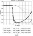
- FIG. 30 is a graphical representation of system temperatures for water and the PCM-based drilling fluid disclosed herein along the well length;
- FIG. 31 is a graphical representation of the effect of cooling a rock face for weakening mechanical strength for preconditioning before destruction by a bit;
- FIG. 32 is graphical representation showing phase state of PCM (Liquid or Solid) along the well length for different flow rates above and below the critical flow rate;
- FIG. 33 is a graphical representation of the fusion temperature range in the tubing and annulus which is controlled by pressure.
- FIG. 34 Is graphical representation showing the effect of BHA delta-P on the cooling performance.
- the technology herein relates to wellbore formation and design with examples for closed-loop geothermal wellbores.
- the design aspect includes:
- the wellbores can be any number of configurations, such as a single U-tube with an inlet/outlet, a U-tube wherein the inlet and outlet well are located on the same surface lease, a “tube-in-tube” configuration which could be vertical, deviated, or horizontal, and include “daisy-chaining” several of these wellbores together, L shaped, etc. These are examples and are not intended to be limiting. Other suitable arrangements will be appreciated by those skilled in the art.
- ii) The “open hole” junctions can be created and sealed while drilling in a single step. This avoids complicated mechanical junctions, cement placement, drilling out plugs or metal sections, multiple trips to surface, and in general the complications and expense associated with intricate downhole processes and resulting delay in forward drilling; iii) There is no material reduction in inner diameter which enables unlimited number of laterals to be drilled; iv) There is no reduction in thermal conductivity created by an insulating cement layer or stagnant annulus between steel liner and rock; and v) Enablement to re-enter multilaterals with magnetic ranging equipment to intersect other lateral wellbores and create a closed U-tube wellbore configuration.
- this may be accomplished by including additives within the drilling fluid itself that cause irreversible formation damage and reduce the permeability to zero or negligible levels.
- the additives may be biological growth accelerants such as the techniques used in Microbial Enhanced Oil Recovery, physical particulates that create an impermeable filter cake, or chemical sealants that react upon contacting and penetrating into the geological formation such as time-set or thermally-set resins and epoxies, gels, and polymers.
- biological growth accelerants such as the techniques used in Microbial Enhanced Oil Recovery, physical particulates that create an impermeable filter cake, or chemical sealants that react upon contacting and penetrating into the geological formation such as time-set or thermally-set resins and epoxies, gels, and polymers.
- Another method for sealing wellbores while drilling is to thermally seal the face of the rock with extremely high temperatures that melt the wellbore wall, for example by using a high temperature plasma or laser-based drilling bit.
- the preferred method is to use a chemical sealant, for example an alkali-silicate based drilling fluid with a pH greater than 10.5, that remains liquid within the wellbore, but precipitates into a solid upon contacting and penetrating into the rock.
- a chemical sealant for example an alkali-silicate based drilling fluid with a pH greater than 10.5, that remains liquid within the wellbore, but precipitates into a solid upon contacting and penetrating into the rock.
- the technical function of the drilling fluid is different in permeable rocks (for example sandstone or fractured basement) relative to impermeable rocks such as hard shales or siltstones.
- permeable rocks for example sandstone or fractured basement
- impermeable rocks such as hard shales or siltstones.
- the liquid alkali-silicate drilling fluid penetrates any available flow paths prior to reacting and setting into a solid.
- the resulting solid precipitate is impregnated and fused into the pore space and natural
- the function of the drilling fluid is not to seal off permeability—the rock already has none. Instead, the function of the drilling fluid is to provide a mechanical and chemical barrier between the rock and wellbore and to fill in any natural fractures, fissures, or cleave planes. The end result is the same, to create a fluid impervious barrier between the wellbore and the geological formation.
- the sealant may also be used to consolidate unconsolidated sands, increase the compressive strength of the rock, and prevent sand production and sloughing.
- soluble silicates contain three components, namely silica, alkali, and water.
- Silica silicon dioxide, SiO 2
- the alkali may be selected from sodium, potassium, or lithium oxide (Na 2 O, K 2 O, or Li 2 O) and is responsible for maintaining the solubility of the silica.
- Suitable silicates include potassium, sodium and sodium aluminosilicate. These products are available in both liquid and powdered forms. Silicates are desirable for use in this technology since they can undergo distinct types of chemical reactions, namely gelation (drop in pH), which is the self-polymerization or condensation of soluble silicate structures to form a hydrous, amorphous gel structure of silicate. Gelation is brought on by a drop in pH with polymerization beginning to rapidly occur at pH below 10.5.
- silicates can undergo is precipitation with cations such as calcium.
- Precipitation of silicate is the cross-linking of silicate molecules by multivalent cations (i.e. Ca +2 , Mg +2 , Al +3 , Fe +3 , etc). These cations are present in the formation water—a drilling fluid to formation fluid interaction therefore results in solid precipitation within the pore space.
- a further type of reaction the silicates undergo is dehydration. As water is removed from liquid silicate, the silicate progressively becomes tackier and more viscous and eventually becomes a glassy film. These are the reactions that occur in the near wellbore as filtrate from the drilling fluid mixes with fluids within the rock matrix.
- Silicates are especially attractive to this geothermal application since they are a stable sealant at ambient conditions and at extremely high temperatures.
- alkali-silicate and sand is used at temperatures of 650° C. and above in the foundry and liquid metal casting industry, and this basic chemical reaction is also employed to seal concrete structures at ambient temperature.
- the alkali-silicate drilling fluid is formulated to be solids free and low viscosity to maximize wellbore fluid invasion and spurt loss to chemically seal the wellbore.
- a lubricant is added that is compatible with silicate brine and does not materially interfere with the sealant properties.
- the concentration of active alkali-silicate can be from 0.3%-10% but more likely from 3%-6% by mass in water. The optimum concentration depends somewhat on the geological properties such as in-situ brine composition and temperature. Higher rock temperatures can cause a delay in the precipitation reaction. Likewise, formations where the in-situ brine has a low concentration of multivalent cations, for example, below 1000 mg/L, cause a slower reaction. Therefore, as rock temperature increases and multivalent cation concentration decreases, the concentration of alkali-silicate should be increased.
- Ancillary benefits of a silicate brine include an enhanced rate of penetration, (ROP), and increased bit life.
- ROP rate of penetration
- the physical properties of the combined rock/sealant material are largely derived from the rock but can be modified by carefully selecting the properties of the sealant.
- a thermally conductive additive may be included with the drilling fluid, such as graphene nano particles, so that the resulting sealant has a high thermal conductivity.
- the energy output of a closed-loop geothermal system can be determined using a thermodynamic wellbore model consisting of a discretized wellbore with multiple thermal resistances between the fluid temperature and the far-field rock temperature. Each discretized segment has an energy and mass balance performed, where fluid properties and calculations are handled with an equation of state thermodynamics package.
- the heat transfer resistances include the rock, cement, steel casing, and convective heat transfer resistance within the wellbore itself.
- the thermal resistances after 5 years of operation for the rock, cement, casing, and pipe flow convection are, respectively, 2.2E-02, 2.1E-03, 2.9E-05, and 5.0E-5.
- the heat transfer is dominated by radial conduction through the rock, and all other thermal resistances are negligible in comparison.
- the chemical sealant described herein there are no resistances to heat transfer from casing or cement, so the thermal efficiency is approximately 9% higher than prior art methodology.
- the alkali-silicate sealant can be further enhanced by incorporating a solid particulate that is formulated to become chemically embedded/bonded within the alkali-silicate precipitate, to improve seal performance and mechanical integrity.
- Reinforcing materials such as exfoliated fly ash, surface-activated graphene and graphene oxide, carbon fibres, and others may be incorporated into the drilling fluid. These may be in a nano-dispersed or micro-dispersed state and chemically bond with the precipitated silica.
- the integrity of the seal is tested. Typically, this is done by pressurizing the wellbore system and monitoring the rate of depressurization, if any, as is common in the industry. Another method is through long-term measurement of the leak-off rate during circulating operations. In this case, the drilling fluid is removed and replaced with the working fluid whose primary purpose is to transfer energy to surface, and the leak-off rate is measured during regular operations.
- the seal will be substantially complete after drilling, there may be some small areas with minor permeability remaining, such as fractured zones or highly permeable channels that were not sufficiently sealed while drilling. Therefore, the seal can be augmented using a chemical flush or treatment prior to commencing or returning to normal operations.
- the drilling fluid reacts with the in-situ formation fluid to gel and eventually solidify into a hard, high strength solid. These reactions happen at the mixing interface between the silicate drilling fluid and the formation fluid.
- the drilling fluid may be migrating through the formation so quickly that the formation fluid is displaced away from the wellbore and the mixing interface is pushed substantially into the rock or the formation brine may be extremely fresh causing the silicate to gel but not completely precipitate.
- the purpose of the chemical flush is pump a chemical treatment through the wellbore system with sufficient pressure to cause leak-off from the wellbore into the near-wellbore formation, contact the unspent liquid alkali-silicate remaining from the drilling process, and initiate the precipitation reaction.
- Suitable chemicals are calcium chloride brine, acids, CO 2 , surfactants, esters, among others known in the industry.
- a chemical treatment may be pumped through the wellbore system with sufficient pressure to cause leak-off from the wellbore into the near-wellbore formation, where the chemical treatment consists of “plugs” or volumes of alkali-silicate followed by a reacting chemical consisting of calcium chloride brine, acids, CO 2 , surfactants, esters, or others known in the industry.
- the two chemicals can be alternatively pumped several times resulting in substantial mixing in the near-wellbore region.
- the volumes of alkali-silicate and reactant may be separated with a spacer to prevent mixing within the wellbore or be in direct contact.
- the drilling process requires maintenance of wellbore integrity and a partial wellbore seal (i.e. a filtercake), for a temporary duration until casing is cemented in the hole or a liner is installed.
- a partial wellbore seal i.e. a filtercake
- the open hole prior to installing casing or liner wellbore integrity and partial seal is created by proper engineering and application of the drilling fluid.
- the invention disclosed herein requires maintaining an open hole seal and wellbore integrity for the operational life of the geothermal asset which is typically 50 years or more.
- the operational working fluid itself has a key role in maintaining the seal and maintaining wellbore integrity.
- the primary function of the working fluid is to transport energy from the subsurface rock to surface where it is directly used or converted into electricity or cooling. Therefore, the working fluid must have key physical properties for energy transfer and to maximize thermodynamic efficiency of the system.
- the fluid may have at least one property selected from the group comprising:
- the working fluid In addition to maximizing thermodynamic efficiency, the working fluid also has many properties of a drilling fluid, namely to:
- the seal may be maintained by providing solid particulates within the working fluid that form a filter cake along the borehole wall or bridge and plug natural fractures.
- These particulates may be carbon fibres, mineral fibres, cellulose fibres, silica, fly ash, graphite, graphene, graphene oxide, calcium carbonate, bentonite, or other particulates known in the industry. These solids are typically added at between 0.5 and 2.0 weight % of the working fluid if its water based, and equivalent volume concentration for other working fluids.
- the drilling fluid reacts with the in-situ formation fluid to gel and eventually solidify into a hard, high strength solid. These reactions happen at the mixing interface between the silicate drilling fluid and the formation fluid.
- the drilling fluid may be migrating through the formation so quickly that the formation fluid is displaced away from the wellbore and the mixing interface is pushed substantially into the rock or the formation brine may be extremely fresh causing the silicate to gel but not completely precipitate.
- a partial or substantial seal is achieved deep within the rock, but the near-wellbore region contains “unspent” or unreacted liquid alkali-silicate drilling fluid and no further formation brine with which to react. Therefore, another method to maintain a seal is to include a reactant additive that upon leaking-off from the wellbore into the near-wellbore formation, contacts the unspent liquid alkali-silicate remaining from the drilling process and initiates the precipitation reaction.
- any areas of the wellbore where permeability remains after drilling will have had considerable influx of alkali-silicate and contain unspent liquid alkali-silicate in the near-wellbore formation. Therefore, including a reactant within the working fluid will naturally seal off the remaining permeable sections.
- Suitable chemicals are calcium chloride brine, acids, CO 2 , surfactants, esters, and others known in the industry.
- the working fluid To maintain wellbore stability and integrity, in addition to sealing the rock, the working fluid must exert enough pressure on the formation to provide sufficient compressive strength to prevent breakouts, sloughing, and partial collapse of rock into the wellbore.
- the pressure that an operational working fluid provides can be calculated using an integrated thermodynamic wellbore model that includes an equation of state to account for phase changes, fluid property changes with pressure and temperature, and hydraulic frictional losses.
- the working fluid When designed appropriately, the working fluid must supply the minimum compressive strength across the entire wellbore, either by applying a sufficiently high pressure at the top of the inlet well (pressurized fluid), or by modifying the density of the working fluid. Fluid density can be increased through addition of weighting agents such as barite or through soluble salts, among other techniques known in the industry.
- Another method to maintain wellbore stability is to include a shale inhibitor chemical within the working fluid.
- This chemical has the function of arresting the hydration, swelling and disintegration of clays and shales, and is a common additive in drilling fluids.
- Suitable additives are amine-based chemicals, latexes, or an aqueous solution of potassium salts, among others known in the industry.
- the working fluid consists of water, a commercially available corrosion inhibitor at between 1 and 10 L/m3, potassium bromide at between 0.05 and 0.3 mol/L, cetyltrimethylammonium surfactant at between 3 and 7 mM, sodium salicylate at between 8 and 16 mM, and calcium carbonate solid particulates at 0.5 weight %.
- the solution described above maintains greater than 60% turbulent drag reduction over a temperature range suitable for direct-use geothermal heat supply, which is critical for thermodynamically efficient operation. It also has over 40% recovery when tested according to API RP 13i Procedures for Shale Dispersion by Hot Rolling, reacts with unspent alkali-silicate to form a strong solid material, and the calcium carbonate particles bridge and plug natural fractures and matrix permeability.
- the working fluid itself is simply a modified alkali-silicate brine.
- the working fluid is supercritical CO 2 which is of particular value since in many geothermal scenarios supercritical CO 2 has thermodynamic efficiency superior to water, and it is also an excellent reactant to cause alkali-silicate liquid to solidify into a strong solid material.
- FIG. 2 is a plot of some data that is typical of the test on a 1 ⁇ 4′′ thick filtration disc.
- a polymer control fluid was flowed through and there is no material reduction of the filtrate volume.
- the filtration rates were slowed drastically as precipitation occurred. Note that the permeability has been nearly eliminated even in a 1 ⁇ 4′′ thick disk with 3000 mD of permeability.
- the total PPT Volume was 273.8 mL for the Formulation A, a spurt loss of 257 mL was calculated, and a Static Filtration Rate of 3.1 mL/min was calculated.
- the total PPT Volume was 103.8 mL for the Formulation B, a spurt loss of 103.8 mL was calculated, and a Static Filtration Rate of 3.7 mL/min was calculated. Values calculated using formulas expressed in API 13i.
- Core flood/regain permeability/core damage studies were also conducted. These types of tests are often used to study the effects of a drilling fluid or drilling fluid additive on the permeability of a core obtained from a target production zone of interest. Usually the object of the study is to minimize the damage or maximize the regain permeability.
- An initial permeability is established and measured by saturating the core with native brine, oil, or some brine/oil mixture, and flowing the formation fluid(s) through the core at pressure at reservoir pressure and temperature conditions. A test fluid is then injected across the face of the core for a certain period of time the volume of filtrate, invasion of fluid, and thickness of filter cake may be measured.
- Formation fluids are then injected in the reverse direction of flow to determine the extent to which the permeability may have decreased or even increased after exposure to the test fluid.
- the aim was to damage the cores by means of gelation and precipitation reactions of the silicate test fluids with the synthetic brine-saturated cores.
- Berea Sandstone cores with permeability approximately 30 mD were saturated with synthetic brine under vacuum and tested with a 3% solution of potassium silicate and containing 2% of a specialty lubricant. Test procedures, parameters and results are set forth below.
- Mud is injected into core at continuous rate of 3 mL/min.
- Test Fluid Potassium silicate at 3% with 2% lubricant
- Shale dispersion testing was then executed to determine the ability of alkali-silicate solutions with lubricant to seal and provide mechanical integrity to shale samples.
- the methodology is according to API RP 13i Procedures for Shale Dispersion by Hot Rolling as follows:
- a working fluid consisting of water, a commercially available corrosion inhibitor, potassium bromide, cetyltrimethylammonium surfactant, sodium salicylate, and calcium carbonate solid particulates at 0.5 weight %.
- Measurement of pressure drop (i.e., drag) and characterization of the turbulent flow was tested using a 2′′ 200 L capacity heated flow.
- the loop is equipped with a centrifugal (GIW, LCC-M 50-230) and a progressive cavity (MoynoTM, 2F090) pump with high and low shear, respectively.
- the maximum Re number reaches 500,000 and the loop can operate with 15% volumetric concentration of solid.
- Pressure drop was calibrated with fresh water and compared to frictional pressure drop at the same flow rate using the working fluid. A turbulent drag reduction of 63% was achieved over a temperature range suitable for direct use heat applications.
- test methodology involves 2 shale dispersion runs back-to-back with the same sample. First, the sample is hot rolled in the sealant, as described above, then re-soaked in the working fluid to determine shale mechanical strength and chemical isolation after sealing. After the initial shale dispersion run with the drilling fluid sealant, the samples are dried, weighed, and immersed in the working fluid chemistry and rolled for 24 hours.
- the mechanism may be effected by adding solid particles to the drilling fluid which migrate naturally into the pore space/fractures to reduce permeability. This is generally known as loss circulation material (LCM).
- LCM loss circulation material
- the solid particles may be granular materials, fibrous materials and flaked materials and combinations of these and be present (dispersed through drilling fluid) in sizes necessary to reduce permeability. Suitable sizes may be nanometer to millimeter in size.
- Abrams' rule and/or Ideal Packing Theory concepts are useful to establish the most suitable materials.
- Abrams' rule proposes particle size of the bridging agent should be equal to or slightly greater than 1 ⁇ 3 the medium pore throat size of the targeted formation.
- the ideal packing theory proposes a full range of particle size distribution to effectively seal all voids, including those created by bridging agents.
- Particles may also be sized to penetrate into the pore space before bridging.
- drill cuttings can augment the LCM and serve as plugging material.
- LCM products could be utilized for remediating wellbore leaks after the drilling process is completed. Further viscous sweeps with LCM may be pumped at a reduced rate through the open hole section to allow invasion of the LCM and seal any leaks.
- solid silicates may also provide an effective chemical/mechanical combination mechanism for sealing the reservoir.
- Microbial Enhanced Oil Recovery is an engineering field which manages the design, growth, and stimulation of microorganisms to increase oil recovery.
- Most deep geological formations contain anaerobic bacteria within the pore space. These bacteria have a very low supply of energy and nutrients compared to near-surface microbes, and thus have low population densities.
- One MEOR technique is to treat the indigenous microbes with nutrients to spur their growth and eventual plugging of the rock porosity with biological material.
- the nutrients may be any chemistry but typically include potassium nitrate and monosodium phosphate.
- bacteria growth is exponential, if supplied with sufficient raw materials and suitable conditions, bacteria can be induced to grow and completely plug off the pore space in which they reside, causing the rock to be substantially impermeable to fluids.
- microbes may be engineered to grow only at a certain temperature and so can be activated by injecting into a hot formation.
- Either technique can be applied to a conventional drilling fluid, causing the rock to be substantially impermeable to fluids, and form a closed-loop geothermal system.
- Geological formations have varying chemistry and thus, varying melting points, although most sedimentary formations melt at 1200° C. or below.
- Several technologies are in the research, development, and testing phase which can penetrate through rock using thermal disintegration rather than mechanical contact.
- One method is to create a plasma either through electric current or nuclear power.
- the plasma melts the rock and enable continuous drilling.
- Another method is to fire lasers onto the surface of the rock, increasing the temperature until the rock begins to spall, disintegrate, and eventually melt.
- Another method is to fire high velocity projectiles which release enough energy on impact to increase temperature by hundreds of degrees.
- FIG. 1 shown is a graphical representation of filtrate volume as a function of the square root of time for different formulations.
- FIG. 2 is a graphical representation of differential pressure and permeability data as a function of time for the chemical sealing core flood test delineated in Example 1.
- FIG. 3 is cross section of a well having an inlet well 10 having surface casing 12 for groundwater protection.
- Intermediate casing 14 is cemented into position as illustrated. All of these components are known in the art.
- Extending from intermediate casing 14 is the lateral section 16 which does not include casing in this example, but rather is the open sealed wellbore. Pore space surrounding the lateral section 16 is sealed with sealant as described herein previously. The sealed pore space is referenced by numeral 18 .
- the sealed lateral section is continuous to intermediate casing 14 .
- the latter casing then continuously connects with outlet well 20 .
- the outlet well is completed with casing 12 .
- FIG. 4 illustrates an alternate scenario.
- the lateral section 16 may be intermittently sealed resulting in unsealed rock face 22 .
- a casing 24 is shown as a liner, meaning lacking cementing.
- the liner 22 thus ameliorates the unsealed rock face and maintains a continuous circuit from the inlet 10 to the outlet 20 . This may be used in conjunction with continuously sealed sections. This will depend upon the specific geology of the formation.
- FIGS. 2 and 3 depict hard rock.
- FIG. 5 shown is an example where the well is disposed within a less permeable section within a formation, an example of which is a sedimentary shale or mudstone section.
- the formation may have infrequent fissures, fractures, cleave planes etc. generally denoted by numeral 26 .
- a chemical liner 28 may be employed to complete the continuity between the inlet 10 and the outlet 20 with the chemical liner composition 28 filling the fissures, fractures and cleave planes as shown.
- each of the inlet 10 and outlet 20 include conventional cased sections 30 which communicate with the inlet 32 and outlet 34 of a multiple lateral well system 36 .
- the system is disposed within a geothermal formation 38 .
- the system 36 includes a plurality of lateral wells 16 , which may be partially cased depending upon the situation as outlined with respect to FIGS. 3 and 4 .
- Any number of well systems 36 may be employed in the formation 38 . This is represented by numeral 6 n vertically and horizontally, with the “n” being indicative of any number of further wells in the shape of the system 36 or any other suitable configuration.
- the inlet 32 and outlet 34 are integrated with the cased sections 30 in a multilateral junction which will now be referenced in the advancing Figures.
- FIG. 7 illustrates one possible multilateral arrangement.
- Inlet 32 connects with a sealed multilateral wellbore junction 40 from which the lateral sections 16 continuously extend.
- the lateral sections 16 are spaced apart from one another to maximize thermal recovery from within the formation 38 ( FIG. 6 ).
- the lateral sections 16 may include casing as discussed with respect to FIGS. 3 through 5 .
- the outlet 34 of the system 36 will include a similar junction 40 (not shown).
- an L-shaped well configuration is shown, generally denoted by numeral 42 .
- the well has an extending section 44 having a terminal end 46 open hole wellbore sealed as with previous examples.
- An insulated tube 48 extends within the well for fluid delivery.
- the extending section 44 may be at any selected angle.
- FIG. 9 illustrates a vertical orientation example.
- a W-shaped well is provided represented by numeral 50 .
- the surface is denoted by numeral 52 .
- output from one well becomes the input of the other well.
- Flow direction is shown with the arrows. The pattern can be repeated for additional cycles.
- the open hole wellbores 16 are sealed as discussed with the previous figures and may incorporate alternating patterns of cased sections with simply sealed wellbore sections. This will depend on the formation geology.
- FIG. 11 illustrates a further variation of a multilateral system similar to that initially referenced in FIG. 3 , which combines the inlet and outlet conduits into a single wellbore, the disposition of the multilateral section may be at any angle within a formation.
- the lateral sections 16 converge at terminal end 54 .
- FIG. 12 is a side view of a single site arrangement 56 where the inlet well 10 and outlet well 20 are generally proximate.
- the fluid circuit is shown for the lateral sections 16 .
- the open hole well bores are sealed while drilling is conducted with the surrounding pore space sealed during the procedure.
- the numeral 12 n carries the same meaning as that ascribed to 6 n referenced in FIG. 6 .
- FIG. 13 A further variation is illustrated in FIG. 13 .
- a top view is shown of a multiple lateral well arrangement.
- the individual wells 16 of the plurality shown share a common inlet well 10 , extend out within the geothermal zone of the formation (not shown in this Figure) and return in a closed circuit to a common outlet well 20 .
- Flow direction is shown with arrows, and flow can be isolated to each individual loop or daisy chain among the separate loops. This is advantageous for a small footprint while allowing for maximum thermal mining within a geothermal zone.
- FIG. 14 depicts a further variation where there are plural well arrangements provided while maintaining the small footprint attributed to the embodiment of FIG. 13 .
- FIG. 15 incorporates the multilateral well system 50 in combination with the well configuration initially presented in FIG. 13 .
- two discrete single sites 56 can span a large area with minimal surface invasiveness to mine a large underground geothermal area.
- Flow direction is shown with arrows, and flow can be isolated to each individual loop or daisy chain among the separate loops.
- the effectiveness of the sealing technology discussed herein permits the flexibility to provide for such hybrid configurations. This, in turn, allows for thermal mining in a wide variety of geologic situations allowing for yet another degree of freedom in practicing the methods herein.
- FIG. 16 illustrates a cross section of a drilled wellbore, also referenced herein as a lateral section 16 .
- the geothermal formation 38 in this example is a high permeability formation. Due to the permeability, the sealant spreads out within the pore space in the formation and immediately proximate the wellbore 16 remains unreacted, referenced by numeral 60 . Outwardly from the unreacted sealant area is pore space sealed with sealant which, as in the previous examples, is denoted by numeral 18 .
- FIG. 17 illustrates the result of exposing the wellbore from FIG. 16 to working fluid. Subsequent to this treatment, the formation area surrounding the wellbore becomes sealed forming an impervious interface between the interior volume of the wellbore itself and the formation surrounding it. This is particularly advantageous since the sealed wellbore 16 is surrounded by a reserve of unreacted sealant 60 . In the event of wellbore seal compromise from seismic activity or other deleterious activity, the wellbore can sustain its integrity and sealing capacity by self healing with the reaction between the reserve of available reactant and the working fluid. This clearly has very significant advantages in terms of reducing operating and maintenance costs over time which, of course, greatly mitigates the initial capital expenditure associated with initially synthesizing the well system.
- the pore space, fractures, fissures, cleave planes etc. may be filled with sealant about the periphery of the wellbore 16 to form an impervious interface in a single step without requiring reactive working fluid or further treatment as depicted in FIG. 18 . Accordingly, it will be realized that geological permeability does not present any geothermal heat mining issues considering the scope of the methods discussed herein.
- the technology can extend into the remediation and retrofit realms.
- One of the foundations of the technology herein is an environmentally friendly solution to energy creation in the geothermal field which circumvents fracturing necessitating unappealing fluid handling.
- a second foundation is that the technology provides a truly closed loop system as opposed to that which has been improperly characterized in the prior art as closed loop.
- the technology allows for a highly effective sealing protocol with the enumerated geothermal recovery benefits, it has been found that the technology can be applied to remediating ineffective, unused or otherwise inoperable geothermal wells. These wells may be unusable or inoperable due to any number of issues such as low flow rates, ineffective fractures, unconsolidated formations and consequent sand production problems, excessive corrosion from the brine, or due leaching problems, among others. Accordingly, where retrofit to a new non fracking geothermal arrangement as discussed herein is not possible, the inoperable site will be abandoned by removal of unnecessary casing and ancillary components, or where possible remediated with expensive and environmentally contentious operations such as fracking or potentially by redrilling entire wells. In light of the fact that permeability degree is not an issue, the sealing technology presents an attractive remediation benefit.
- the well loop 64 comprises a closed loop system having an inlet well 10 and an outlet well 20 , disposed within a geological formation, which may be, for example, a geothermal formation, low permeability formation, sedimentary formation, volcanic formation or “basement’ formation which is more appropriately described as crystalline rock occurring beneath the sedimentary basin (none being shown).
- a geological formation which may be, for example, a geothermal formation, low permeability formation, sedimentary formation, volcanic formation or “basement’ formation which is more appropriately described as crystalline rock occurring beneath the sedimentary basin (none being shown).
- the well loop 64 and power cycle 66 are in thermal contact by heat exchanger 68 which recovers heat from the working fluid circulating in the loop 64 in the formation which is subsequently used to generate power with generator 70 in cycle 66 .
- the temperature of the formation may be in the range of between 80° C. and 150° C.
- the fluids may be modified with additives to prevent freezing at subzero ° C. temperatures.
- Suitable additives include, anti-scaling agents, anti-corrosion agents, friction reducers, and anti-freezing chemicals, refrigerants, biocides, hydrocarbons, alcohols, organic fluids and combinations thereof.
- a substantial benefit of the tailored well-loop working fluid in combination with the segregated power cycle is that it is unaffected by very cold ambient temperatures and thus facilitates use of any generic power cycle (including ORC, Kalina, carbon carrier cycle, CTPC) to be used to increase higher net power production when used in conjunction with a well loop as set forth in FIG. 19 .
- any generic power cycle including ORC, Kalina, carbon carrier cycle, CTPC
- heat is transferred from the first working fluid to the second working fluid when the temperature of the second working fluid is at zero ° C. or subzero ° C.
- FIGS. 20 and 21 Optional arrangements with the segregated circuit are illustrated in FIGS. 20 and 21 .
- FIG. 20 illustrates a segregated circuit incorporating a well loop 64 in thermal contact with two distinct heat exchangers 68 each with its own power generator 70 forming a parallel arrangement.
- FIG. 21 illustrates a serial arrangement.
- the integrated well loop power cycle is a closed loop system in which the selected working fluid is circulated within the well loop and then flows into a turbine on surface as shown in FIG. 22 .
- Numeral 72 denotes the overall process schematic. In this process, a single-fluid is used rather than having a discrete well loop fluid and a secondary power cycle working fluid.
- the working fluid in this closed loop cycle can operate either as a transcritical cycle, whereby the fluid is supercritical at the upper working pressure and subcritical at the lower working pressure, or as an entirely supercritical cycle whereby the fluid remains supercritical at the lower working pressure.
- FIG. 23 illustrates an alternate embodiment.
- a transcritical cycle is a thermodynamic cycle where the working fluid goes through both the subcritical and supercritical states.
- the apparatus further includes a cooling device, shown in the example as an aerial cooler 74 and turbine 76 with generator 78 .
- the aerial cooler 74 is used to cool the working fluid to a temperature between 1° C. and 15° C. above ambient temperature. It is also to be noted that the working fluid can be cooled to a subzero ° C. temperature. Reference to FIG. 24 delineates performance data.
- the driving mechanism in this integrated cycle is a very strong thermosiphon which arises due to the density difference between the inlet vertical well 10 and the outlet vertical well 20 .
- the fluid is in a supercritical liquid state in the inlet well 10 , heats up as it travels along the lateral interconnecting sections 80 and exits in a supercritical state in the outlet well 20 , which creates significant pressure.
- thermosiphon effect can completely eliminate the need for a surface pump under normal operating conditions except during start-up.
- this eliminates the power required to operate the pump and increase the net electrical power output.
- An example of this type of fluid for use in a segregated configuration is an aqueous precipitate/electrolyte solution with temperature-dependent solubility, wherein the water is super saturated at the top of the inlet well.
- the solid particles are held in suspension with an anti-scaling agent (anti-flocculation agent) and with turbulent flow (similar to a drilling mud).
- anti-scaling agent anti-flocculation agent
- turbulent flow similar to a drilling mud
- Useful fluids include aqueous solutions with the following solutes as examples: Ammonium acetate, ammonium dihydrogen phosphate, ammonium formate, ammonium nitrate, potassium bromide, potassium chloride, potassium formate, potassium hydrogen carbonate, potassium nitrate, sodium acetate, sodium carbonate and monosodium phosphate.
- control logic (not shown) automatically shifts the working fluid to the appropriate turbine to maintain high efficiency throughout the year.
- each surface location generally denoted by numeral 84 , includes an injection well 86 connected to a lateral well conduit or interconnecting segment 88 and production well 90 .
- the continuous well structure subscribes to a generally U-shaped structure.
- the lateral well segment may comprise a well system 36 , as discussed in FIG. 3 or any of the other configurations discussed previously.
- each location 84 is discrete and linked to proximal locations in an elegant and advantageous manner.
- the distance between locations may be 3,500 meters to 6000 meters. This will, of course, vary from one situation to another.
- working fluid is circulated in the injection well 86 of one location 84 , optionally processed through, for example, a power generation apparatus (not shown) to recover the heat energy and subsequently passed as an output stream to be an inlet feed stream for a injection well 86 of a proximal location 84 .
- the chain line 92 illustrates this relay or daisy chain sequencing. Since not all of the heat is recovered, the inlet feed stream for well 86 of a proximal location is preheated for injection into lateral conduit 88 . The process then resets for repetition in the next location 84 .
- FIG. 26 shown is a further embodiment of the invention for example, a 8,000 kW to 12,000 kW system.
- individual loops may be joined at a centralized location 94 in order to centralize the power generation apparatus (not shown) for increased power and efficiency.
- FIGS. 27 and 28 illustrate smaller scale operations, 4,000 kW-6,000 kW ( FIG. 27 ) and 2,000 kW-3,000 kW ( FIG. 28 ).
- phase change materials PCM
- PCMs undergo fusion (melting and solidifying) at a nearly constant temperature—hence, they absorb and release thermal energy without changing temperature materially.
- fusion melting and solidifying
- thermal energy without changing temperature materially.
- the unification of these properties with the sealing while drilling in sequence with drilling with PCMs with subsequent sealing has a dramatic positive impact on efficient drilling utilizing conventional drilling equipment in high temperature formations otherwise no achievable with standard equipment.
- the PCMs are added to the drilling fluid, and the fluid is pumped at a sufficient flow rate so that the PCMs undergo a phase change throughout the system (or at minimum proximate the bottom hole assembly (not shown).
- the PCMs are pumped in solid state (or mostly solid state).
- the fluid 98 descends the tubing 100 of the string 96 , heat is transferred from the returning fluid 102 in the annulus 104 —however, the heat transfer rate is small due to the close temperature match (low delta T) between the annulus 104 and tubing 100 .
- the fluid 98 in tubing 100 absorbs thermal energy while descending and melts without materially changing temperature and exits the bit 106 either in completely solid state or with a higher liquid fraction than at the top of the tubing 100 .
- thermodynamics of the system are designed so that the flowing PCM slurry in the drill string 96 remains at least partially in solid state at, or near, the bottom hole assembly (not shown). This operation may be sequenced with a drill while sealing operation in any sequence as has been referenced herein previously.
- Phase change slurry, (PCS) Casing is the slurry temperature of the returning fluid in the annulus 24 110 between the casing 26 112 and drill string 10 96 , when the PCS is flowing at 4 m3/min. With water flowing at 4 m3/min, the temperature at the BHA (not shown) is approximately 222° C. Increasing the water flow rate to 5 m3/min only cools the BHA down to 209° C. The PCS fluid enables cooling down to 160° C. at 4 m3/min, much lower than achievable with water.
- drilling rate of penetration is a function of rock strength. It has been found that here can weaken the rock, or “pre-condition” the rock, prior to physical destruction with the bit, by inducing a rapid cooling shock. By maintaining a much lower circulating fluid temperature than the in-situ rock temperature, the cool drilling fluid induces localized thermal contraction in the rock near the bit face (not shown). This contraction causes the rock to weaken and can even cause tensile failure.
- the rock can be cooled by greater than 100° C.
- Reference to FIG. 30 shows cooling of 190° C.
- FIG. 31 depicts the rock mechanical strength as a function of the shock cooling delta-T, that is, the temperature difference between the PCM drilling fluid and the virgin rock temperature.
- a particularly useful application of the invention is for construction of closed-loop, conduction-only geothermal systems as disclosed in Applicant's copending applications. These systems typically require magnetic ranging tools to enable intersection of the various wellbores to create a closed system.
- the receiver can be placed on the end of a drill string (tubing) and configured to allow fluid to flow through the tool and out of the end of the tubing. In this manner, the magnetic ranging equipment can be actively cooled by pumping a PCS at high rates through the tool and back up the annulus, using the design and operational methodology described herein.
- the PCMs are designed and selected to have a fusion temperature below the maximum temperature limit of the equipment, electronics, and sensors within the drill string and BHA. Therefore, even though the rock temperature can be significantly higher than the equipment maximum temperature limit, the drilling fluid temperature remains at the PCM fusion temperature.
- Rock temperatures above 200° C. to 400° C. and greater can be drilled with standard directional drilling equipment, electronics, etc. Furthermore, some wells are currently drilled with expensive high temperature tools up to 250° C. In contrast, the technology disclosed herein enables much cheaper, more reliable and effective equipment, saving significant costs.
- U.S. Pat. No. 9,758,711 discloses a PCS drilling fluid to cool the bit and bottom hole assembly.
- the disclosure does not enable sufficient cooling to weaken rock for faster ROP, or solve the operational challenges necessary to achieve a massive cooling effect.
- the critical flow rate is defined by that where the PCM remains at least partly solid (therefore undergoing fusion) throughout the entire drill string and exits the bit (or bottom hole assembly) in partially solid form. It is not necessary to have the PCM in solid form in the annulus, only the tubing.
- FIG. 32 different flow rates for a scenario of drilling 340° C. rock (a linear 75° C./km geothermal gradient) at 4500 m depth, with a fusion temperature of 150° C., are illustrated.
- the temperature at the bottom hole assembly for each flow rate is 180, 150, 150° C., for 2.5, 2.9, 3.0 m3/min, respectively. Therefore, the critical flow rate is 2.9 m3/min in this scenario, as any lower flow rate results in higher temperatures at the BHA, while any higher flow rate results in no additional cooling.
- the critical flow rate is between 2 m3/min and 6 m3/min.
- FIG. 34 shows a graphical representation showing the importance of properly designing the delta-P across the BHA. It depicts two cases each with identical flow rate, drilling fluid composition, well dimensions, and rock temperature. Case 1 has no pressure drop, or delta-P, across the equipment and components at the bottom of the string (Bottom Hole Assembly). Case 2 has a pressure drop of 10 MPa. The fluid temperature at the bit is 230° C. and 160° C. respectively.
- Rock cuttings which are transported to surface need to be removed to maintain the required solids content/density of the drilling fluid.
- a clear fluid is ideal—meaning a fluid with immaterial solids content. While larger cuttings are removed via screens/shakers, smaller solids are removed with a centrifuge which separates the higher density material. Therefore, the PCM should be chosen to have a density similar to that of the base carrier fluid, and ideally slightly below the carrier fluid, to enable removal of cuttings in a centrifuge but leave the PCM particles within the fluid.
- Adding solid PCM to a base carrier fluid such as water increases the effective bulk viscosity significantly. As viscosity increases, so does the hydraulic frictional pressure drop through the wellbore. The high pressure losses would usually dictate massive surface pumping power and high pressure equipment.
- the PCM can be chosen to have a significant density difference between the liquid and solid states. By combining this PCM property with an optimized fluid composition and flow rate, the system is designed/operated so that the PCM has a significantly higher % solid phase in the drill string than in the annulus, thus creating a large density difference between the drill string and annulus, enabling a significant siphoning effect. The siphoning effect adds a large pressure drive to the system which partially overcomes the impact of the increased viscosity from the PCM.
- the density difference is not a thermosiphon as the temperature in the tubing/annulus is essentially the same. Instead the siphon is caused by the relative phase state of the PCM between the annulus and tubing.
- the daisy chaining since well loops are linked front to back, eliminates the need for a near surface return conduit. Further, the paired loops act as the return conduit for each other with the pair using waste heat as an input to create the preheated stream supra.
- the wells in the examples are formed by employing the sealing while drilling methodology described. It will be understood that any combination of well configurations can be incorporated in the daisy type arrangement. Further, any combination of destructive techniques may be used to form the wellbores in the daisy example as well as any of the other configurations shown in all of the Figures.
- reference to an “n” designation is included together with the Figure number.
- An example is FIG. 6 having an area denoted 6 n . This is to represent that any number, thus n, of additional wells may be stacked vertically or positioned in a parallel relationship or both with the one shown.
- the well type may be different or the same for the additional wells.
- the technology set forth herein is predicated on the ability to form a geothermal formation, regardless of permeability, into an energy efficient wellbore for maximum conductivity. This capability, when coupled with highly effective working fluids, results in remarkable methodology.
- Fluid circulation within the wells can occur in any pattern and direction that facilitates efficiency. This will be partly dictated by the nature of the formation and will determined and appreciated by those skilled in the art.
Landscapes
- Engineering & Computer Science (AREA)
- Life Sciences & Earth Sciences (AREA)
- Geology (AREA)
- Mining & Mineral Resources (AREA)
- General Life Sciences & Earth Sciences (AREA)
- Physics & Mathematics (AREA)
- Environmental & Geological Engineering (AREA)
- Fluid Mechanics (AREA)
- Geochemistry & Mineralogy (AREA)
- Mechanical Engineering (AREA)
- Sustainable Development (AREA)
- Sustainable Energy (AREA)
- Chemical & Material Sciences (AREA)
- Combustion & Propulsion (AREA)
- General Engineering & Computer Science (AREA)
- Geophysics (AREA)
- Earth Drilling (AREA)
- Physical Or Chemical Processes And Apparatus (AREA)
Priority Applications (2)
| Application Number | Priority Date | Filing Date | Title |
|---|---|---|---|
| US17/126,153 US12209775B2 (en) | 2020-04-21 | 2020-12-18 | Forming high efficiency geothermal wellbores |
| US18/943,448 US20250146713A1 (en) | 2020-04-21 | 2024-11-11 | Forming High-Efficiency Geothermal Wellbores |
Applications Claiming Priority (4)
| Application Number | Priority Date | Filing Date | Title |
|---|---|---|---|
| US202063012952P | 2020-04-21 | 2020-04-21 | |
| CA3100013A CA3100013C (fr) | 2020-04-21 | 2020-11-19 | Methode de formation de puits geothermiques de grande efficacite au moyen de materiaux a changement de phase |
| CA3100013 | 2020-11-19 | ||
| US17/126,153 US12209775B2 (en) | 2020-04-21 | 2020-12-18 | Forming high efficiency geothermal wellbores |
Related Child Applications (1)
| Application Number | Title | Priority Date | Filing Date |
|---|---|---|---|
| US18/943,448 Continuation US20250146713A1 (en) | 2020-04-21 | 2024-11-11 | Forming High-Efficiency Geothermal Wellbores |
Publications (2)
| Publication Number | Publication Date |
|---|---|
| US20210325089A1 US20210325089A1 (en) | 2021-10-21 |
| US12209775B2 true US12209775B2 (en) | 2025-01-28 |
Family
ID=77271629
Family Applications (2)
| Application Number | Title | Priority Date | Filing Date |
|---|---|---|---|
| US17/126,153 Active US12209775B2 (en) | 2020-04-21 | 2020-12-18 | Forming high efficiency geothermal wellbores |
| US18/943,448 Pending US20250146713A1 (en) | 2020-04-21 | 2024-11-11 | Forming High-Efficiency Geothermal Wellbores |
Family Applications After (1)
| Application Number | Title | Priority Date | Filing Date |
|---|---|---|---|
| US18/943,448 Pending US20250146713A1 (en) | 2020-04-21 | 2024-11-11 | Forming High-Efficiency Geothermal Wellbores |
Country Status (5)
| Country | Link |
|---|---|
| US (2) | US12209775B2 (fr) |
| AR (1) | AR120893A1 (fr) |
| CA (1) | CA3100013C (fr) |
| TW (1) | TW202140914A (fr) |
| WO (1) | WO2021212201A1 (fr) |
Families Citing this family (23)
| Publication number | Priority date | Publication date | Assignee | Title |
|---|---|---|---|---|
| CA3044153C (fr) | 2018-07-04 | 2020-09-15 | Eavor Technologies Inc. | Procede de formation de puits de forage geothermique a haute efficacite |
| CA3144627A1 (fr) | 2019-06-27 | 2020-12-27 | Eavor Technologies Inc. | Protocole operationnel pour la recolte d'une formation a production thermique |
| CA3138740C (fr) | 2020-01-25 | 2023-01-03 | Eavor Technologies Inc | Methode de production d`alimentation sur demande au moyen de recuperation thermique geologique |
| CA3085901C (fr) * | 2020-07-06 | 2024-01-09 | Eavor Technologies Inc. | Methode de configuration de puits de forage dans une formation geologique |
| PE20230970A1 (es) | 2020-08-28 | 2023-06-16 | Eavor Tech Inc | Refrigeracion para perforacion de pozos geotermicos |
| FR3117196B1 (fr) * | 2020-12-08 | 2023-03-17 | Ifp Energies Now | Système d’échange de chaleur entre un bâtiment et le sous-sol terrestre comprenant la circulation en circuit fermé de matériaux à changement de phase |
| US12123406B2 (en) * | 2021-08-18 | 2024-10-22 | Babak Bob Arefi | Geothermal processes and systems for enhancing electricity generation via increasing a pressure on a primary fluid |
| AU2021474106B2 (en) * | 2021-11-17 | 2026-04-23 | Eavor Technologies Inc. | Mitigating fluid loss or inflow in a closed-loop geothermal system |
| CN114370267B (zh) * | 2021-12-17 | 2023-06-13 | 核工业北京地质研究院 | 一种高温地热田钻进过程中钻遇热储温度的实时计算方法 |
| CN114198016B (zh) * | 2021-12-31 | 2022-09-16 | 北京派创石油技术服务有限公司 | 地热闭环工质循环开采方法 |
| CN114482923B (zh) * | 2022-01-25 | 2023-06-30 | 中国石油大学(华东) | 一种考虑材料相变的钻井液循环换热控制方法及系统 |
| EP4473187A4 (fr) * | 2022-02-01 | 2025-12-31 | Xgs Energy Inc | Systèmes et procédés d'amélioration de la portée thermique |
| AU2023215561A1 (en) | 2022-02-04 | 2024-09-12 | Novus Earth Energy Operations Inc. | Balanced geothermal energy transfer loop |
| CN114152555B (zh) * | 2022-02-09 | 2022-04-15 | 成都理工大学 | 一种钻井液漏失损害模拟装置及方法 |
| US12577853B2 (en) | 2022-04-12 | 2026-03-17 | David Holland | System, method and apparatus for generating electric power from subsurface wells |
| CN114673479B (zh) * | 2022-05-07 | 2022-11-08 | 中国矿业大学 | 一种基于多相态co2的层位式地热强化开采方法 |
| CN114837609B (zh) * | 2022-06-08 | 2023-05-16 | 西南石油大学 | 一种气体钻井随钻等离子热熔喷涂造壁固壁工具及方法 |
| US11708818B1 (en) | 2022-10-17 | 2023-07-25 | Roda Energy Corporation | Systems for generating energy from geothermal sources and methods of operating and constructing same |
| CN115828775A (zh) * | 2022-11-03 | 2023-03-21 | 华中科技大学 | 一种超临界二氧化碳锅炉炉膛热力分析方法 |
| CN115788402B (zh) * | 2022-12-01 | 2024-07-02 | 重庆页岩气勘探开发有限责任公司 | 一种页岩气水平井焖井时间确定方法、设备及储存介质 |
| CN116104720A (zh) * | 2023-01-30 | 2023-05-12 | 东北大学 | 一种延长热突破时间的干热岩开采系统及开采方法 |
| US12305621B2 (en) | 2023-06-12 | 2025-05-20 | Roda Energy Corporation | Systems for generating energy from geothermal sources and methods of operating and constructing same |
| WO2025199175A1 (fr) * | 2024-03-18 | 2025-09-25 | David Holland | Système, procédé et appareil pour produire du courant électrique à partir de puits souterrains |
Citations (144)
| Publication number | Priority date | Publication date | Assignee | Title |
|---|---|---|---|---|
| US3424254A (en) | 1965-12-29 | 1969-01-28 | Major Walter Huff | Cryogenic method and apparatus for drilling hot geothermal zones |
| US3786858A (en) | 1972-03-27 | 1974-01-22 | Atomic Energy Commission | Method of extracting heat from dry geothermal reservoirs |
| US3817038A (en) | 1972-09-01 | 1974-06-18 | Texaco Development Corp | Method for heating a fluid |
| US4060988A (en) | 1975-04-21 | 1977-12-06 | Texaco Inc. | Process for heating a fluid in a geothermal formation |
| US4137720A (en) | 1977-03-17 | 1979-02-06 | Rex Robert W | Use of calcium halide-water as a heat extraction medium for energy recovery from hot rock systems |
| GB2097448A (en) | 1981-04-24 | 1982-11-03 | Grace W R & Co | Hight temperature stable fluid loss control system |
| US4665985A (en) | 1984-02-17 | 1987-05-19 | Rhone-Poulenc Recherches | Reversible plugging of oil bearing formations |
| US4741405A (en) | 1987-01-06 | 1988-05-03 | Tetra Corporation | Focused shock spark discharge drill using multiple electrodes |
| JPH0350874A (ja) | 1989-07-19 | 1991-03-05 | Sony Corp | 不揮発性メモリ装置 |
| JPH04203195A (ja) | 1990-11-30 | 1992-07-23 | Terunaito:Kk | 逸水防止工法 |
| JPH0637827A (ja) | 1992-07-15 | 1994-02-10 | Matsushita Electric Works Ltd | Fm受信装置の同期確定方式 |
| CA2123075A1 (fr) | 1993-05-14 | 1994-11-15 | Cameron M. Matthews | Methode et appareil de forage de puits et de production de liquide |
| JPH07260054A (ja) | 1994-03-17 | 1995-10-13 | Nippon Steel Corp | トルク抵抗の優れたドリルパイプ継手 |
| US5515679A (en) | 1995-01-13 | 1996-05-14 | Jerome S. Spevack | Geothermal heat mining and utilization |
| US5685362A (en) | 1996-01-22 | 1997-11-11 | The Regents Of The University Of California | Storage capacity in hot dry rock reservoirs |
| US5687999A (en) | 1995-10-03 | 1997-11-18 | Vallourec Oil & Gas | Threaded joint for tubes |
| CA2210866A1 (fr) | 1996-07-19 | 1998-01-19 | Gaz De France (G.D.F) Service National | Procede d'excavation souterraine dans une mince formation de sel |
| US5715895A (en) | 1996-04-23 | 1998-02-10 | Champness; Elwood | Downhole drilling tool cooling system |
| US5803185A (en) | 1995-02-25 | 1998-09-08 | Camco Drilling Group Limited Of Hycalog | Steerable rotary drilling systems and method of operating such systems |
| EP0875657A2 (fr) | 1997-03-14 | 1998-11-04 | Halliburton Energy Services, Inc. | Méthode pour étanchéifier des zones souterraines |
| US5911282A (en) * | 1997-08-18 | 1999-06-15 | Halliburton Energy Services, Inc. | Well drilling fluids containing epoxy sealants and methods |
| US5992507A (en) | 1998-03-20 | 1999-11-30 | Phillips Petroleum Company | Geothermal community loop field |
| US6000471A (en) | 1995-01-27 | 1999-12-14 | Langset; Einar | Hole in the ground for transfer of geothermal energy to an energy-carrying liquid and a method for production of the hole |
| US6028534A (en) | 1997-06-02 | 2000-02-22 | Schlumberger Technology Corporation | Formation data sensing with deployed remote sensors during well drilling |
| US6059036A (en) | 1997-11-26 | 2000-05-09 | Halliburton Energy Services, Inc. | Methods and compositions for sealing subterranean zones |
| US6073448A (en) | 1998-08-27 | 2000-06-13 | Lozada; Vince M. | Method and apparatus for steam generation from isothermal geothermal reservoirs |
| US6102120A (en) | 1996-12-13 | 2000-08-15 | Schlumberger Technology Corporation | Zone isolation tools |
| US6247313B1 (en) | 1996-11-22 | 2001-06-19 | Per H. Moe | Plant for exploiting geothermal energy |
| US6301894B1 (en) | 2000-05-12 | 2001-10-16 | Albert H. Halff | Geothermal power generator |
| CA2449302A1 (fr) | 2001-06-18 | 2002-12-27 | Richard S. Polizzotti | Procede et systeme de forage hydrothermique |
| JP3091479U (ja) | 2002-07-16 | 2003-01-31 | 明煌 張 | 通風性ドア構造 |
| US6626243B1 (en) | 1999-08-24 | 2003-09-30 | Bj Services Company | Methods and compositions for use in cementing in cold environments |
| WO2003106585A1 (fr) | 2002-06-13 | 2003-12-24 | Halliburton Energy Services, Inc. | Procedes permettant de renforcer des formations ou de former un cuvelage chimique, ou les deux, pendant une operation de forage |
| US6668554B1 (en) | 1999-09-10 | 2003-12-30 | The Regents Of The University Of California | Geothermal energy production with supercritical fluids |
| US6679326B2 (en) | 2002-01-15 | 2004-01-20 | Bohdan Zakiewicz | Pro-ecological mining system |
| US6708494B1 (en) | 1999-07-09 | 2004-03-23 | Klett-Ingenieur-Gmbh | Device for utlilizing geothermal heat and method for operating the same |
| US20040123985A1 (en) | 2002-12-31 | 2004-07-01 | Whitfill Donald L. | Method for drilling depleted sands with minimal drilling fluid loss |
| US6938707B2 (en) * | 2003-05-15 | 2005-09-06 | Chevron U.S.A. Inc. | Method and system for minimizing circulating fluid return losses during drilling of a well bore |
| US7000711B2 (en) | 2004-02-09 | 2006-02-21 | Ch2M Hill, Inc. | Horizontal bore cryogenic drilling method |
| US20060108150A1 (en) | 2003-12-04 | 2006-05-25 | Karen Luke | Drilling and cementing with fluids containing zeolite |
| US20060250274A1 (en) | 2005-04-18 | 2006-11-09 | Core Laboratories Canada Ltd | Systems and methods for acquiring data in thermal recovery oil wells |
| US7146823B1 (en) | 2004-06-22 | 2006-12-12 | Earth To Air Systems, Llc | Horizontal and vertical direct exchange heating/cooling system sub-surface tubing installation means |
| US7198107B2 (en) | 2004-05-14 | 2007-04-03 | James Q. Maguire | In-situ method of producing oil shale and gas (methane) hydrates, on-shore and off-shore |
| US7207603B2 (en) | 2003-03-11 | 2007-04-24 | Grant Prideco, L.P. | Insulated tubular assembly |
| US7251938B1 (en) | 2002-10-11 | 2007-08-07 | The Board Of Regents For The University Of Oklahoma | System and method for recovering geothermal energy and for converting recovered geothermal energy into useful power |
| JP2007198723A (ja) | 2006-01-13 | 2007-08-09 | Soilmec Spa | 地熱エネルギー開発プラントにおいて流体を循環させるために地盤を掘削するシステム |
| CN101027480A (zh) | 2004-06-23 | 2007-08-29 | 特拉瓦特控股公司 | 开发和生产深部地热储集层的方法 |
| US20070223999A1 (en) | 2004-06-23 | 2007-09-27 | Terrawatt Holdings Corporation | Method of Developing and Producing Deep Geothermal Reservoirs |
| US20070245729A1 (en) | 2006-04-21 | 2007-10-25 | Mickleson D Lynn | Directional geothermal energy system and method |
| WO2008003092A2 (fr) | 2006-06-29 | 2008-01-03 | Tetra Corporation | Foret d'électroconcassage portable et directionnel |
| US20080190614A1 (en) | 2007-02-09 | 2008-08-14 | M-I Llc | Silicate-based wellbore fluid and methods for stabilizing unconsolidated formations |
| US20090014180A1 (en) | 2006-10-20 | 2009-01-15 | George Leo Stegemeier | Moving hydrocarbons through portions of tar sands formations with a fluid |
| WO2010027866A2 (fr) | 2008-08-26 | 2010-03-11 | Tetra Corporation | Appareil de forage de roche électrique pulsé avec trépan non rotatif et commande de direction |
| US20100071366A1 (en) | 2008-09-23 | 2010-03-25 | Skibo Systems, LLC | Methods and Systems for Electric Power Generation Using Geothermal Field Enhancements |
| WO2010072407A1 (fr) | 2008-12-23 | 2010-07-01 | Eth Zurich | Forage de roches à de grandes profondeurs par fragmentation thermique en utilisant les réactions hautement exothermiques se déroulant dans un milieu de fluide de forage à base d'eau |
| CN201593889U (zh) | 2010-02-01 | 2010-09-29 | 长沙北极熊节能环保技术有限公司 | 一种地源热泵地埋管布置新装置 |
| US20100243242A1 (en) | 2009-03-27 | 2010-09-30 | Boney Curtis L | Method for completing tight oil and gas reservoirs |
| US20100276115A1 (en) | 2008-08-05 | 2010-11-04 | Parrella Michael J | System and method of maximizing heat transfer at the bottom of a well using heat conductive components and a predictive model |
| US20110011557A1 (en) | 2009-07-14 | 2011-01-20 | Shelton Tommie Jr | System to enable geothermal field interaction with existing hvac systems, method to enable geothermal field interaction with existing hvac system |
| US20110048005A1 (en) | 2009-08-26 | 2011-03-03 | Mchargue Timothy Reed | Loop geothermal system |
| US20110061382A1 (en) | 2009-09-17 | 2011-03-17 | Stern Richard H | System and Method for Extracting Geothermal Energy From a Potentially Seismically Active Stratum, With Reduced Accompanying Seismic Disturbances |
| US20110067869A1 (en) | 2009-10-14 | 2011-03-24 | Bour Daniel L | In situ decomposition of carbonyls at high temperature for fixing incomplete and failed well seals |
| US20110100002A1 (en) | 2009-11-02 | 2011-05-05 | Greenfire Partners Llc | Process to obtain thermal and kinetic energy from a geothermal heat source using supercritical co2 |
| WO2011053884A1 (fr) | 2009-10-30 | 2011-05-05 | Qualcomm Incorporated | Procédés et systèmes pour la découverte de réseau poste à poste utilisant la diversité multiutilisateur |
| CA2790616A1 (fr) | 2010-02-22 | 2011-08-25 | Siemens Aktiengesellschaft | Dispositif et procede d'extraction, notamment d'extraction in-situ, d'une substance carbonee situee dans un gisement souterrain |
| US20110224942A1 (en) | 2010-03-11 | 2011-09-15 | Kidwell John E | GPS-tracking ground heat exchanger (GHE) performance test instrumentation network supporting a plurality of wireless portable GPS-based enthalpy-based GHE performance test instrumentation systems |
| US8020382B1 (en) | 2008-12-23 | 2011-09-20 | Geothermic Solution LLC | Closed loop, hot dry rock heat recovery process |
| US20110247816A1 (en) | 2008-12-10 | 2011-10-13 | Carter Jr Ernest E | Method and Apparatus for Increasing Well Productivity |
| US20110306524A1 (en) | 2007-03-09 | 2011-12-15 | Techstar Energy Services Inc. | Drilling fluid and methods |
| US20120080163A1 (en) | 2009-04-20 | 2012-04-05 | Anzoic Energy Inc. | Subterranean continuous loop heat exchanger, method of manufacture and method to heat, cool or store energy with same |
| WO2012068279A2 (fr) | 2010-11-16 | 2012-05-24 | InnerGeo LLC | Système et procédé pour extraire de l'énergie |
| WO2012082962A1 (fr) | 2010-12-14 | 2012-06-21 | Altarock Energy, Inc. | Matériau de déviation et de perte de circulation temporaire à haute température |
| US20120174581A1 (en) | 2011-01-06 | 2012-07-12 | Vaughan Susanne F | Closed-Loop Systems and Methods for Geothermal Electricity Generation |
| CN102758595A (zh) | 2012-06-05 | 2012-10-31 | 徐毅 | 地热系统的井喷处理装置 |
| US8307896B2 (en) | 2009-04-27 | 2012-11-13 | Alberto Sarria | Two-concentric pipe system to heat fluids using the earth's interior thermal energy (deep) |
| WO2013013174A2 (fr) | 2011-07-20 | 2013-01-24 | Inventus Holdings, Llc | Installation de génération, de commande et de stockage d'énergie renouvelable à répartir |
| US8381523B2 (en) | 2009-05-27 | 2013-02-26 | Zadok Eli | Geothermal electricity production methods and geothermal energy collection systems |
| WO2013109890A2 (fr) | 2012-01-19 | 2013-07-25 | General Compression, Inc. | Système et procédé permettant de préserver les ressources énergétiques par le stockage et la distribution d'énergie renouvelable |
| US20130255258A1 (en) | 2012-04-02 | 2013-10-03 | Ronald Lee Loveday | Rankine Cycle System |
| WO2013152138A1 (fr) | 2012-04-03 | 2013-10-10 | Onset Inc. | Production et fourniture d'énergie stable à partir de ressources renouvelables |
| US20130299036A1 (en) | 2012-05-13 | 2013-11-14 | Ronald Lee Loveday | Conduit for improved fluid flow and heat transfer |
| US20130338835A1 (en) | 2012-06-14 | 2013-12-19 | Christopher Mark Pepe | Cogeneration System and Process for Determining Whether to Use Cogeneration |
| US8616000B2 (en) | 2008-06-13 | 2013-12-31 | Michael J. Parrella | System and method of capturing geothermal heat from within a drilled well to generate electricity |
| WO2014008483A1 (fr) | 2012-07-05 | 2014-01-09 | Sdg, Llc | Appareils et procédés d'alimentation en électricité de trépan d'électroconcassage |
| JP2014051856A (ja) | 2012-09-10 | 2014-03-20 | Hirosaki Univ | 発電方法及び発電システム |
| US8708046B2 (en) | 2007-11-16 | 2014-04-29 | Conocophillips Company | Closed loop energy production from geothermal reservoirs |
| US20140133519A1 (en) | 2012-11-13 | 2014-05-15 | Braun Intertec Geothermal, Llc | Equipment and methods for designing geothermal heat exchange systems |
| US20140130498A1 (en) | 2012-11-12 | 2014-05-15 | Jimmy Bryan Randolph | Carbon dioxide-based geothermal energy generation systems and methods related thereto |
| US8727035B2 (en) * | 2010-08-05 | 2014-05-20 | Schlumberger Technology Corporation | System and method for managing temperature in a wellbore |
| WO2014081911A2 (fr) | 2012-11-21 | 2014-05-30 | Aavid Thermalloy, Llc | Système et procédé pour collecte de chaleur géothermique |
| US8822386B2 (en) | 2010-06-28 | 2014-09-02 | Baker Hughes Incorporated | Nanofluids and methods of use for drilling and completion fluids |
| US20140326668A1 (en) | 2013-05-06 | 2014-11-06 | Innergeo | Using geopressure to desalinate water |
| CN203978273U (zh) | 2014-07-11 | 2014-12-03 | 贵州有色地质工程勘察公司 | 碳酸盐岩及硬质岩石地埋管钻孔及灌浆装置 |
| US20140367172A1 (en) | 2013-06-14 | 2014-12-18 | Ryan Directional Services | Drill string with aluminum drill pipes, bent housing, and motor |
| WO2015030601A1 (fr) | 2013-08-27 | 2015-03-05 | Geovarme As | Centrale d'énergie géothermique et procédé d'installation associé |
| GB2518442A (en) | 2013-09-23 | 2015-03-25 | Statoil Petroleum As | Method of treating a borehole |
| US9016374B2 (en) * | 2009-06-12 | 2015-04-28 | Baker Hughes Incorporated | Heat removal in drilling and production operations |
| US9027669B2 (en) * | 2011-08-02 | 2015-05-12 | Halliburton Energy Services, Inc. | Cooled-fluid systems and methods for pulsed-electric drilling |
| US20150198019A1 (en) | 2014-01-12 | 2015-07-16 | Joseph A. Affholter | In Situ Retorting of Hydrocarbons and Selected Metal |
| US9121393B2 (en) | 2010-12-10 | 2015-09-01 | Schwarck Structure, Llc | Passive heat extraction and electricity generation |
| WO2015134974A1 (fr) | 2014-03-07 | 2015-09-11 | Greenfire Energy Inc | Processus et procédé de production d'énergie géothermique |
| US20150285049A1 (en) | 2014-04-07 | 2015-10-08 | Maximo Tejeda | Method of Drilling for and Producing Oil and Gas from Earth Boreholes |
| US9212304B2 (en) | 2011-03-21 | 2015-12-15 | Pq Corporation | Use of high ratio aqueous alkali silicates in drilling fluids |
| WO2015192011A1 (fr) | 2014-06-13 | 2015-12-17 | Greenfire Energy Inc | Systèmes de production d'énergie à boucle géothermique |
| US9243485B2 (en) * | 2013-02-05 | 2016-01-26 | Triple D Technologies, Inc. | System and method to initiate permeability in bore holes without perforating tools |
| US20160040518A1 (en) | 2014-08-06 | 2016-02-11 | Schlumberger Technology Corporation | Well treatment fluids |
| WO2016091969A1 (fr) | 2014-12-09 | 2016-06-16 | Energeotek Ab | Système de fourniture d'énergie provenant d'une source géothermique |
| JP2016118078A (ja) | 2014-12-23 | 2016-06-30 | ソリューション・クリエイターズ株式会社 | 地熱抽出の促進方法及び地熱抽出促進型閉ループ循環地熱発電システム |
| US20160211664A1 (en) | 2013-08-26 | 2016-07-21 | Robert Bosch Gmbh | Dispatch Controller for an Energy System |
| US20160273345A1 (en) | 2013-12-23 | 2016-09-22 | Halliburton Energy Services Inc. | Method and System for Magnetic Ranging and Geosteering |
| US9458023B2 (en) | 2012-09-20 | 2016-10-04 | Pq Corporation | Use of aqueous alkali aluminosilicate for profile modification, water control and stabilization |
| US9512705B2 (en) | 2012-10-16 | 2016-12-06 | Halliburton Energy Services, Inc. | Multilateral bore junction isolation |
| CN106246101A (zh) | 2016-09-23 | 2016-12-21 | 太原理工大学 | 一种用干冰钻井液辅助破岩的钻井方法 |
| CN106246142A (zh) | 2016-08-30 | 2016-12-21 | 湖南中大经纬地热开发科技有限公司 | 一种基于复杂岩土地层的地热井 |
| US9556856B2 (en) | 2007-07-06 | 2017-01-31 | Greenfield Master Ipco Limited | Geothermal energy system and method of operation |
| CN106368608A (zh) | 2016-08-26 | 2017-02-01 | 中国石油大学(北京) | 一种利用液氮进行干热岩钻井的新方法 |
| JP2017025730A (ja) | 2015-07-17 | 2017-02-02 | 株式会社大林組 | 地熱採取方法および地熱採取システム |
| US20170058181A1 (en) | 2015-04-29 | 2017-03-02 | Halliburton Energy Services, Inc. | Grout fluids for use in a geothermal well loop |
| WO2017053884A1 (fr) | 2015-09-24 | 2017-03-30 | Geothermic Solution, Llc | Extracteurs de chaleur géothermique |
| US20170130116A1 (en) | 2015-11-11 | 2017-05-11 | Pq Corporation | Self-Pressurizing Soluble Alkali Silicate for use in Sealing Subterranean Spaces |
| US20170137694A1 (en) | 2015-11-18 | 2017-05-18 | Board Of Regents, The University Of Texas System | Cementitious compositions comprising a non-aqueous fluid and an alkali-activated material |
| WO2017146712A1 (fr) | 2016-02-25 | 2017-08-31 | Greenfire Energy Inc. | Récupération de chaleur géothermique à partir de formations géologiques à haute température et à faible perméabilité pour la production d'énergie à l'aide de systèmes à boucle fermée |
| US20170299226A1 (en) | 2014-06-20 | 2017-10-19 | Lawrence Livermore National Security, Llc | Multi-fluid renewable geo-energy systems and methods |
| US9803626B1 (en) | 2014-05-08 | 2017-10-31 | Greenfire Energy Inc. | Thermosiphoning supercritical CO2 in geothermal energy production |
| US9850767B2 (en) | 2014-08-08 | 2017-12-26 | United Technologies Corporation | Aluminum fan blade tip with thermal barrier |
| WO2018112610A1 (fr) | 2016-12-23 | 2018-06-28 | Grant Nevison | Amélioration de la production d'énergie géothermique dans un puits |
| WO2018136033A1 (fr) | 2017-01-17 | 2018-07-26 | Halliburton Energy Services, Inc. | Trépan pour forage par électro-concassage de fond de trou |
| US10060195B2 (en) | 2006-06-29 | 2018-08-28 | Sdg Llc | Repetitive pulsed electric discharge apparatuses and methods of use |
| CA2998782A1 (fr) | 2017-04-08 | 2018-10-08 | Alberta Geothermal Corporation | Procede et appareil de recyclage de puits pour la production d'energie dans un environnement geothermique |
| RU2670292C1 (ru) | 2014-09-22 | 2018-10-22 | Куреха Корпорейшн | Скважинный инструмент, оснащенный элементом скважинного инструмента, содержащим химически активный металл, и элементом скважинного инструмента, содержащим разлагаемую смоляную композицию, и способ бурения скважин |
| CN109652028A (zh) | 2018-12-29 | 2019-04-19 | 中石化石油工程技术服务有限公司 | 一种基于相变材料的钻井液温度控制方法 |
| CA3013374A1 (fr) | 2017-10-31 | 2019-04-30 | Eavor Technologies Inc. | Methode et appareil de recyclage de sites de forage en vue de la production d'energie geothermique |
| CA3041002A1 (fr) | 2017-11-18 | 2019-05-18 | Eavor Technologies Inc. | Methode de production d'energie geothermique avec des boucles de puits fermees a l'aide de joints d'etancheite |
| CA3038294A1 (fr) | 2018-05-10 | 2019-06-26 | Eavor Technologies Inc. | Fluide destine a des environnements de production d'energie |
| WO2019157341A1 (fr) | 2018-02-08 | 2019-08-15 | Greenfire Energy Inc. | Production d'énergie en boucle fermée à partir de puits géothermiques de production |
| WO2019164691A1 (fr) | 2018-02-20 | 2019-08-29 | Saudi Arabian Oil Company | Scanner tridimensionnel pour reconstruction d'intégrité de puits de fond de trou dans l'industrie des hydrocarbures |
| CA3044153A1 (fr) | 2018-07-04 | 2020-01-04 | Eavor Technologies Inc. | Procede de formation de puits de forage geothermique a haute efficacite |
| US20200049380A1 (en) | 2018-08-12 | 2020-02-13 | Eavor Technologies Inc. | Method for thermal profile control and energy recovery in geothermal wells |
| US10774617B2 (en) * | 2018-12-21 | 2020-09-15 | China Petroleum & Chemical Corporation | Downhole drilling system |
| US20200299562A1 (en) | 2016-06-16 | 2020-09-24 | Halliburton Energy Services, Inc. | Drilling fluid for downhole electrocrushing drilling |
| WO2020236189A1 (fr) | 2019-05-23 | 2020-11-26 | Halliburton Energy Services, Inc. | Reconfiguration de fond de trou de composants de système de forage à impulsions d'énergie pendant des opérations de forage à impulsions |
| US20210396079A1 (en) | 2018-10-30 | 2021-12-23 | The Texas A&M University System | Systems and Methods for Forming a Subterranean Borehole |
| WO2022155743A1 (fr) | 2021-01-20 | 2022-07-28 | Arrow Geothermal Inc. | Forage à haute température et procédés d'utilisation |
| US20230228155A1 (en) | 2020-08-28 | 2023-07-20 | Eavor Technologies Inc. | Cooling for geothermal well drilling |
-
2020
- 2020-11-19 CA CA3100013A patent/CA3100013C/fr active Active
- 2020-11-24 TW TW109141187A patent/TW202140914A/zh unknown
- 2020-12-17 WO PCT/CA2020/000136 patent/WO2021212201A1/fr not_active Ceased
- 2020-12-18 US US17/126,153 patent/US12209775B2/en active Active
- 2020-12-23 AR ARP200103638A patent/AR120893A1/es unknown
-
2024
- 2024-11-11 US US18/943,448 patent/US20250146713A1/en active Pending
Patent Citations (172)
| Publication number | Priority date | Publication date | Assignee | Title |
|---|---|---|---|---|
| US3424254A (en) | 1965-12-29 | 1969-01-28 | Major Walter Huff | Cryogenic method and apparatus for drilling hot geothermal zones |
| US3786858A (en) | 1972-03-27 | 1974-01-22 | Atomic Energy Commission | Method of extracting heat from dry geothermal reservoirs |
| US3817038A (en) | 1972-09-01 | 1974-06-18 | Texaco Development Corp | Method for heating a fluid |
| US4060988A (en) | 1975-04-21 | 1977-12-06 | Texaco Inc. | Process for heating a fluid in a geothermal formation |
| US4137720A (en) | 1977-03-17 | 1979-02-06 | Rex Robert W | Use of calcium halide-water as a heat extraction medium for energy recovery from hot rock systems |
| GB2097448A (en) | 1981-04-24 | 1982-11-03 | Grace W R & Co | Hight temperature stable fluid loss control system |
| US4665985A (en) | 1984-02-17 | 1987-05-19 | Rhone-Poulenc Recherches | Reversible plugging of oil bearing formations |
| US4741405A (en) | 1987-01-06 | 1988-05-03 | Tetra Corporation | Focused shock spark discharge drill using multiple electrodes |
| JPH0350874A (ja) | 1989-07-19 | 1991-03-05 | Sony Corp | 不揮発性メモリ装置 |
| JPH04203195A (ja) | 1990-11-30 | 1992-07-23 | Terunaito:Kk | 逸水防止工法 |
| JPH0637827A (ja) | 1992-07-15 | 1994-02-10 | Matsushita Electric Works Ltd | Fm受信装置の同期確定方式 |
| CA2123075A1 (fr) | 1993-05-14 | 1994-11-15 | Cameron M. Matthews | Methode et appareil de forage de puits et de production de liquide |
| JPH07260054A (ja) | 1994-03-17 | 1995-10-13 | Nippon Steel Corp | トルク抵抗の優れたドリルパイプ継手 |
| US5515679A (en) | 1995-01-13 | 1996-05-14 | Jerome S. Spevack | Geothermal heat mining and utilization |
| US6000471A (en) | 1995-01-27 | 1999-12-14 | Langset; Einar | Hole in the ground for transfer of geothermal energy to an energy-carrying liquid and a method for production of the hole |
| US5803185A (en) | 1995-02-25 | 1998-09-08 | Camco Drilling Group Limited Of Hycalog | Steerable rotary drilling systems and method of operating such systems |
| US5687999A (en) | 1995-10-03 | 1997-11-18 | Vallourec Oil & Gas | Threaded joint for tubes |
| US5685362A (en) | 1996-01-22 | 1997-11-11 | The Regents Of The University Of California | Storage capacity in hot dry rock reservoirs |
| US5715895A (en) | 1996-04-23 | 1998-02-10 | Champness; Elwood | Downhole drilling tool cooling system |
| CA2210866A1 (fr) | 1996-07-19 | 1998-01-19 | Gaz De France (G.D.F) Service National | Procede d'excavation souterraine dans une mince formation de sel |
| US6247313B1 (en) | 1996-11-22 | 2001-06-19 | Per H. Moe | Plant for exploiting geothermal energy |
| US6102120A (en) | 1996-12-13 | 2000-08-15 | Schlumberger Technology Corporation | Zone isolation tools |
| EP0875657A2 (fr) | 1997-03-14 | 1998-11-04 | Halliburton Energy Services, Inc. | Méthode pour étanchéifier des zones souterraines |
| US6028534A (en) | 1997-06-02 | 2000-02-22 | Schlumberger Technology Corporation | Formation data sensing with deployed remote sensors during well drilling |
| US5911282A (en) * | 1997-08-18 | 1999-06-15 | Halliburton Energy Services, Inc. | Well drilling fluids containing epoxy sealants and methods |
| US6059036A (en) | 1997-11-26 | 2000-05-09 | Halliburton Energy Services, Inc. | Methods and compositions for sealing subterranean zones |
| US5992507A (en) | 1998-03-20 | 1999-11-30 | Phillips Petroleum Company | Geothermal community loop field |
| US6073448A (en) | 1998-08-27 | 2000-06-13 | Lozada; Vince M. | Method and apparatus for steam generation from isothermal geothermal reservoirs |
| US6708494B1 (en) | 1999-07-09 | 2004-03-23 | Klett-Ingenieur-Gmbh | Device for utlilizing geothermal heat and method for operating the same |
| US6626243B1 (en) | 1999-08-24 | 2003-09-30 | Bj Services Company | Methods and compositions for use in cementing in cold environments |
| US6668554B1 (en) | 1999-09-10 | 2003-12-30 | The Regents Of The University Of California | Geothermal energy production with supercritical fluids |
| US6301894B1 (en) | 2000-05-12 | 2001-10-16 | Albert H. Halff | Geothermal power generator |
| CA2449302A1 (fr) | 2001-06-18 | 2002-12-27 | Richard S. Polizzotti | Procede et systeme de forage hydrothermique |
| WO2002103152A1 (fr) | 2001-06-18 | 2002-12-27 | Exxonmobil Research And Engineering Company | Procede et systeme de forage hydrothermique |
| US6679326B2 (en) | 2002-01-15 | 2004-01-20 | Bohdan Zakiewicz | Pro-ecological mining system |
| WO2003106585A1 (fr) | 2002-06-13 | 2003-12-24 | Halliburton Energy Services, Inc. | Procedes permettant de renforcer des formations ou de former un cuvelage chimique, ou les deux, pendant une operation de forage |
| US6702044B2 (en) | 2002-06-13 | 2004-03-09 | Halliburton Energy Services, Inc. | Methods of consolidating formations or forming chemical casing or both while drilling |
| JP3091479U (ja) | 2002-07-16 | 2003-01-31 | 明煌 張 | 通風性ドア構造 |
| US7251938B1 (en) | 2002-10-11 | 2007-08-07 | The Board Of Regents For The University Of Oklahoma | System and method for recovering geothermal energy and for converting recovered geothermal energy into useful power |
| US20040123985A1 (en) | 2002-12-31 | 2004-07-01 | Whitfill Donald L. | Method for drilling depleted sands with minimal drilling fluid loss |
| EP1435428A2 (fr) | 2002-12-31 | 2004-07-07 | Halliburton Energy Services, Inc. | Colmatage de sables appauvris , en fond de puits |
| US7207603B2 (en) | 2003-03-11 | 2007-04-24 | Grant Prideco, L.P. | Insulated tubular assembly |
| US6938707B2 (en) * | 2003-05-15 | 2005-09-06 | Chevron U.S.A. Inc. | Method and system for minimizing circulating fluid return losses during drilling of a well bore |
| US20060108150A1 (en) | 2003-12-04 | 2006-05-25 | Karen Luke | Drilling and cementing with fluids containing zeolite |
| US7000711B2 (en) | 2004-02-09 | 2006-02-21 | Ch2M Hill, Inc. | Horizontal bore cryogenic drilling method |
| US7198107B2 (en) | 2004-05-14 | 2007-04-03 | James Q. Maguire | In-situ method of producing oil shale and gas (methane) hydrates, on-shore and off-shore |
| US7146823B1 (en) | 2004-06-22 | 2006-12-12 | Earth To Air Systems, Llc | Horizontal and vertical direct exchange heating/cooling system sub-surface tubing installation means |
| CN101027480A (zh) | 2004-06-23 | 2007-08-29 | 特拉瓦特控股公司 | 开发和生产深部地热储集层的方法 |
| US20100272515A1 (en) | 2004-06-23 | 2010-10-28 | Curlett Harry B | Method of developing and producing deep geothermal reservoirs |
| US20070223999A1 (en) | 2004-06-23 | 2007-09-27 | Terrawatt Holdings Corporation | Method of Developing and Producing Deep Geothermal Reservoirs |
| US7753122B2 (en) | 2004-06-23 | 2010-07-13 | Terrawatt Holdings Corporation | Method of developing and producing deep geothermal reservoirs |
| US20060250274A1 (en) | 2005-04-18 | 2006-11-09 | Core Laboratories Canada Ltd | Systems and methods for acquiring data in thermal recovery oil wells |
| JP2007198723A (ja) | 2006-01-13 | 2007-08-09 | Soilmec Spa | 地熱エネルギー開発プラントにおいて流体を循環させるために地盤を掘削するシステム |
| US20070245729A1 (en) | 2006-04-21 | 2007-10-25 | Mickleson D Lynn | Directional geothermal energy system and method |
| US10060195B2 (en) | 2006-06-29 | 2018-08-28 | Sdg Llc | Repetitive pulsed electric discharge apparatuses and methods of use |
| WO2008003092A2 (fr) | 2006-06-29 | 2008-01-03 | Tetra Corporation | Foret d'électroconcassage portable et directionnel |
| US20090014180A1 (en) | 2006-10-20 | 2009-01-15 | George Leo Stegemeier | Moving hydrocarbons through portions of tar sands formations with a fluid |
| US7740068B2 (en) * | 2007-02-09 | 2010-06-22 | M-I Llc | Silicate-based wellbore fluid and methods for stabilizing unconsolidated formations |
| US20080190614A1 (en) | 2007-02-09 | 2008-08-14 | M-I Llc | Silicate-based wellbore fluid and methods for stabilizing unconsolidated formations |
| US20110306524A1 (en) | 2007-03-09 | 2011-12-15 | Techstar Energy Services Inc. | Drilling fluid and methods |
| US9556856B2 (en) | 2007-07-06 | 2017-01-31 | Greenfield Master Ipco Limited | Geothermal energy system and method of operation |
| US8708046B2 (en) | 2007-11-16 | 2014-04-29 | Conocophillips Company | Closed loop energy production from geothermal reservoirs |
| US8616000B2 (en) | 2008-06-13 | 2013-12-31 | Michael J. Parrella | System and method of capturing geothermal heat from within a drilled well to generate electricity |
| US20100276115A1 (en) | 2008-08-05 | 2010-11-04 | Parrella Michael J | System and method of maximizing heat transfer at the bottom of a well using heat conductive components and a predictive model |
| WO2010027866A2 (fr) | 2008-08-26 | 2010-03-11 | Tetra Corporation | Appareil de forage de roche électrique pulsé avec trépan non rotatif et commande de direction |
| US20100071366A1 (en) | 2008-09-23 | 2010-03-25 | Skibo Systems, LLC | Methods and Systems for Electric Power Generation Using Geothermal Field Enhancements |
| US20110247816A1 (en) | 2008-12-10 | 2011-10-13 | Carter Jr Ernest E | Method and Apparatus for Increasing Well Productivity |
| US8020382B1 (en) | 2008-12-23 | 2011-09-20 | Geothermic Solution LLC | Closed loop, hot dry rock heat recovery process |
| WO2010072407A1 (fr) | 2008-12-23 | 2010-07-01 | Eth Zurich | Forage de roches à de grandes profondeurs par fragmentation thermique en utilisant les réactions hautement exothermiques se déroulant dans un milieu de fluide de forage à base d'eau |
| US20100243242A1 (en) | 2009-03-27 | 2010-09-30 | Boney Curtis L | Method for completing tight oil and gas reservoirs |
| US20120080163A1 (en) | 2009-04-20 | 2012-04-05 | Anzoic Energy Inc. | Subterranean continuous loop heat exchanger, method of manufacture and method to heat, cool or store energy with same |
| US8307896B2 (en) | 2009-04-27 | 2012-11-13 | Alberto Sarria | Two-concentric pipe system to heat fluids using the earth's interior thermal energy (deep) |
| US8381523B2 (en) | 2009-05-27 | 2013-02-26 | Zadok Eli | Geothermal electricity production methods and geothermal energy collection systems |
| US9758711B2 (en) | 2009-06-12 | 2017-09-12 | Baker Hughes Incorporated | Heat removal in drilling and production operations |
| US9016374B2 (en) * | 2009-06-12 | 2015-04-28 | Baker Hughes Incorporated | Heat removal in drilling and production operations |
| US20110011557A1 (en) | 2009-07-14 | 2011-01-20 | Shelton Tommie Jr | System to enable geothermal field interaction with existing hvac systems, method to enable geothermal field interaction with existing hvac system |
| US8672058B2 (en) | 2009-07-14 | 2014-03-18 | Geothermal Technologies, Inc. | Method for repairing aberrations along a drill bore wall |
| US20110048005A1 (en) | 2009-08-26 | 2011-03-03 | Mchargue Timothy Reed | Loop geothermal system |
| US20110061382A1 (en) | 2009-09-17 | 2011-03-17 | Stern Richard H | System and Method for Extracting Geothermal Energy From a Potentially Seismically Active Stratum, With Reduced Accompanying Seismic Disturbances |
| US20110067869A1 (en) | 2009-10-14 | 2011-03-24 | Bour Daniel L | In situ decomposition of carbonyls at high temperature for fixing incomplete and failed well seals |
| WO2011053884A1 (fr) | 2009-10-30 | 2011-05-05 | Qualcomm Incorporated | Procédés et systèmes pour la découverte de réseau poste à poste utilisant la diversité multiutilisateur |
| US20110100002A1 (en) | 2009-11-02 | 2011-05-05 | Greenfire Partners Llc | Process to obtain thermal and kinetic energy from a geothermal heat source using supercritical co2 |
| CN201593889U (zh) | 2010-02-01 | 2010-09-29 | 长沙北极熊节能环保技术有限公司 | 一种地源热泵地埋管布置新装置 |
| CA2790616A1 (fr) | 2010-02-22 | 2011-08-25 | Siemens Aktiengesellschaft | Dispositif et procede d'extraction, notamment d'extraction in-situ, d'une substance carbonee situee dans un gisement souterrain |
| US20110224942A1 (en) | 2010-03-11 | 2011-09-15 | Kidwell John E | GPS-tracking ground heat exchanger (GHE) performance test instrumentation network supporting a plurality of wireless portable GPS-based enthalpy-based GHE performance test instrumentation systems |
| US8822386B2 (en) | 2010-06-28 | 2014-09-02 | Baker Hughes Incorporated | Nanofluids and methods of use for drilling and completion fluids |
| US8727035B2 (en) * | 2010-08-05 | 2014-05-20 | Schlumberger Technology Corporation | System and method for managing temperature in a wellbore |
| WO2012068279A2 (fr) | 2010-11-16 | 2012-05-24 | InnerGeo LLC | Système et procédé pour extraire de l'énergie |
| US8991488B2 (en) | 2010-11-16 | 2015-03-31 | InnerGeo LLC | System and method for extracting energy |
| US9121393B2 (en) | 2010-12-10 | 2015-09-01 | Schwarck Structure, Llc | Passive heat extraction and electricity generation |
| WO2012082962A1 (fr) | 2010-12-14 | 2012-06-21 | Altarock Energy, Inc. | Matériau de déviation et de perte de circulation temporaire à haute température |
| US20120174581A1 (en) | 2011-01-06 | 2012-07-12 | Vaughan Susanne F | Closed-Loop Systems and Methods for Geothermal Electricity Generation |
| US9212304B2 (en) | 2011-03-21 | 2015-12-15 | Pq Corporation | Use of high ratio aqueous alkali silicates in drilling fluids |
| WO2013013174A2 (fr) | 2011-07-20 | 2013-01-24 | Inventus Holdings, Llc | Installation de génération, de commande et de stockage d'énergie renouvelable à répartir |
| US9279322B2 (en) | 2011-08-02 | 2016-03-08 | Halliburton Energy Services, Inc. | Systems and methods for pulsed-flow pulsed-electric drilling |
| US9027669B2 (en) * | 2011-08-02 | 2015-05-12 | Halliburton Energy Services, Inc. | Cooled-fluid systems and methods for pulsed-electric drilling |
| WO2013109890A2 (fr) | 2012-01-19 | 2013-07-25 | General Compression, Inc. | Système et procédé permettant de préserver les ressources énergétiques par le stockage et la distribution d'énergie renouvelable |
| US20130255258A1 (en) | 2012-04-02 | 2013-10-03 | Ronald Lee Loveday | Rankine Cycle System |
| WO2013152138A1 (fr) | 2012-04-03 | 2013-10-10 | Onset Inc. | Production et fourniture d'énergie stable à partir de ressources renouvelables |
| US20130299036A1 (en) | 2012-05-13 | 2013-11-14 | Ronald Lee Loveday | Conduit for improved fluid flow and heat transfer |
| CN102758595A (zh) | 2012-06-05 | 2012-10-31 | 徐毅 | 地热系统的井喷处理装置 |
| US20130338835A1 (en) | 2012-06-14 | 2013-12-19 | Christopher Mark Pepe | Cogeneration System and Process for Determining Whether to Use Cogeneration |
| WO2014008483A1 (fr) | 2012-07-05 | 2014-01-09 | Sdg, Llc | Appareils et procédés d'alimentation en électricité de trépan d'électroconcassage |
| JP2014051856A (ja) | 2012-09-10 | 2014-03-20 | Hirosaki Univ | 発電方法及び発電システム |
| US9458023B2 (en) | 2012-09-20 | 2016-10-04 | Pq Corporation | Use of aqueous alkali aluminosilicate for profile modification, water control and stabilization |
| US9512705B2 (en) | 2012-10-16 | 2016-12-06 | Halliburton Energy Services, Inc. | Multilateral bore junction isolation |
| US20140130498A1 (en) | 2012-11-12 | 2014-05-15 | Jimmy Bryan Randolph | Carbon dioxide-based geothermal energy generation systems and methods related thereto |
| US9869167B2 (en) | 2012-11-12 | 2018-01-16 | Terracoh Inc. | Carbon dioxide-based geothermal energy generation systems and methods related thereto |
| US20140133519A1 (en) | 2012-11-13 | 2014-05-15 | Braun Intertec Geothermal, Llc | Equipment and methods for designing geothermal heat exchange systems |
| WO2014081911A2 (fr) | 2012-11-21 | 2014-05-30 | Aavid Thermalloy, Llc | Système et procédé pour collecte de chaleur géothermique |
| US9243485B2 (en) * | 2013-02-05 | 2016-01-26 | Triple D Technologies, Inc. | System and method to initiate permeability in bore holes without perforating tools |
| US20140326668A1 (en) | 2013-05-06 | 2014-11-06 | Innergeo | Using geopressure to desalinate water |
| WO2014182732A1 (fr) | 2013-05-06 | 2014-11-13 | Innergeo | Utilisation de la géopression pour dessaler l'eau |
| US20140367172A1 (en) | 2013-06-14 | 2014-12-18 | Ryan Directional Services | Drill string with aluminum drill pipes, bent housing, and motor |
| US20160211664A1 (en) | 2013-08-26 | 2016-07-21 | Robert Bosch Gmbh | Dispatch Controller for an Energy System |
| US10260778B2 (en) | 2013-08-27 | 2019-04-16 | Geovarme As | Geothermal power plant |
| US20160245550A1 (en) | 2013-08-27 | 2016-08-25 | Geovarme As | Geothermal power plant |
| WO2015030601A1 (fr) | 2013-08-27 | 2015-03-05 | Geovarme As | Centrale d'énergie géothermique et procédé d'installation associé |
| GB2518442A (en) | 2013-09-23 | 2015-03-25 | Statoil Petroleum As | Method of treating a borehole |
| US20160273345A1 (en) | 2013-12-23 | 2016-09-22 | Halliburton Energy Services Inc. | Method and System for Magnetic Ranging and Geosteering |
| US20150198019A1 (en) | 2014-01-12 | 2015-07-16 | Joseph A. Affholter | In Situ Retorting of Hydrocarbons and Selected Metal |
| US20170211849A1 (en) | 2014-03-07 | 2017-07-27 | Greenfire Energy Inc | Process and method of producing geothermal power |
| WO2015134974A1 (fr) | 2014-03-07 | 2015-09-11 | Greenfire Energy Inc | Processus et procédé de production d'énergie géothermique |
| US20150285049A1 (en) | 2014-04-07 | 2015-10-08 | Maximo Tejeda | Method of Drilling for and Producing Oil and Gas from Earth Boreholes |
| US9803626B1 (en) | 2014-05-08 | 2017-10-31 | Greenfire Energy Inc. | Thermosiphoning supercritical CO2 in geothermal energy production |
| WO2015192011A1 (fr) | 2014-06-13 | 2015-12-17 | Greenfire Energy Inc | Systèmes de production d'énergie à boucle géothermique |
| US20170299226A1 (en) | 2014-06-20 | 2017-10-19 | Lawrence Livermore National Security, Llc | Multi-fluid renewable geo-energy systems and methods |
| CN203978273U (zh) | 2014-07-11 | 2014-12-03 | 贵州有色地质工程勘察公司 | 碳酸盐岩及硬质岩石地埋管钻孔及灌浆装置 |
| US20160040518A1 (en) | 2014-08-06 | 2016-02-11 | Schlumberger Technology Corporation | Well treatment fluids |
| US9850767B2 (en) | 2014-08-08 | 2017-12-26 | United Technologies Corporation | Aluminum fan blade tip with thermal barrier |
| RU2670292C1 (ru) | 2014-09-22 | 2018-10-22 | Куреха Корпорейшн | Скважинный инструмент, оснащенный элементом скважинного инструмента, содержащим химически активный металл, и элементом скважинного инструмента, содержащим разлагаемую смоляную композицию, и способ бурения скважин |
| WO2016091969A1 (fr) | 2014-12-09 | 2016-06-16 | Energeotek Ab | Système de fourniture d'énergie provenant d'une source géothermique |
| JP2016118078A (ja) | 2014-12-23 | 2016-06-30 | ソリューション・クリエイターズ株式会社 | 地熱抽出の促進方法及び地熱抽出促進型閉ループ循環地熱発電システム |
| US9845423B2 (en) | 2015-04-29 | 2017-12-19 | Halliburton Energy Services, Inc. | Grout fluids for use in a geothermal well loop |
| US20170058181A1 (en) | 2015-04-29 | 2017-03-02 | Halliburton Energy Services, Inc. | Grout fluids for use in a geothermal well loop |
| JP2017025730A (ja) | 2015-07-17 | 2017-02-02 | 株式会社大林組 | 地熱採取方法および地熱採取システム |
| WO2017053884A1 (fr) | 2015-09-24 | 2017-03-30 | Geothermic Solution, Llc | Extracteurs de chaleur géothermique |
| CN108291437A (zh) | 2015-09-24 | 2018-07-17 | 地热解决方案有限责任公司 | 地热热量采收机 |
| US20180274524A1 (en) | 2015-09-24 | 2018-09-27 | Geothermic Solution, Llc | Geothermal heat harvesters |
| US20170130116A1 (en) | 2015-11-11 | 2017-05-11 | Pq Corporation | Self-Pressurizing Soluble Alkali Silicate for use in Sealing Subterranean Spaces |
| US20170137694A1 (en) | 2015-11-18 | 2017-05-18 | Board Of Regents, The University Of Texas System | Cementitious compositions comprising a non-aqueous fluid and an alkali-activated material |
| US20190055930A1 (en) | 2016-02-25 | 2019-02-21 | Greenfire Energy Inc | Geothermal heat recovery from high-temperature, low-permeability geologic formations for power generation using closed loop systems |
| WO2017146712A1 (fr) | 2016-02-25 | 2017-08-31 | Greenfire Energy Inc. | Récupération de chaleur géothermique à partir de formations géologiques à haute température et à faible perméabilité pour la production d'énergie à l'aide de systèmes à boucle fermée |
| JP6735839B2 (ja) | 2016-02-25 | 2020-08-05 | グリーンファイヤー エナジー インコーポレイテッド | 閉ループシステムを用いる発電のための高温低透過性地層からの地中熱回収 |
| US10527026B2 (en) | 2016-02-25 | 2020-01-07 | Greenfire Energy Inc. | Geothermal heat recovery from high-temperature, low-permeability geologic formations for power generation using closed loop systems |
| US20200299562A1 (en) | 2016-06-16 | 2020-09-24 | Halliburton Energy Services, Inc. | Drilling fluid for downhole electrocrushing drilling |
| CN106368608A (zh) | 2016-08-26 | 2017-02-01 | 中国石油大学(北京) | 一种利用液氮进行干热岩钻井的新方法 |
| CN106246142A (zh) | 2016-08-30 | 2016-12-21 | 湖南中大经纬地热开发科技有限公司 | 一种基于复杂岩土地层的地热井 |
| CN106246101A (zh) | 2016-09-23 | 2016-12-21 | 太原理工大学 | 一种用干冰钻井液辅助破岩的钻井方法 |
| WO2018112610A1 (fr) | 2016-12-23 | 2018-06-28 | Grant Nevison | Amélioration de la production d'énergie géothermique dans un puits |
| WO2018136033A1 (fr) | 2017-01-17 | 2018-07-26 | Halliburton Energy Services, Inc. | Trépan pour forage par électro-concassage de fond de trou |
| CA2998782A1 (fr) | 2017-04-08 | 2018-10-08 | Alberta Geothermal Corporation | Procede et appareil de recyclage de puits pour la production d'energie dans un environnement geothermique |
| CA3013374A1 (fr) | 2017-10-31 | 2019-04-30 | Eavor Technologies Inc. | Methode et appareil de recyclage de sites de forage en vue de la production d'energie geothermique |
| CA3041002A1 (fr) | 2017-11-18 | 2019-05-18 | Eavor Technologies Inc. | Methode de production d'energie geothermique avec des boucles de puits fermees a l'aide de joints d'etancheite |
| WO2019095032A1 (fr) | 2017-11-18 | 2019-05-23 | Eavor Technologies Inc. | Procédé et appareil de production d'énergie |
| US20190154010A1 (en) | 2017-11-18 | 2019-05-23 | Eavor Technologies Inc. | Method and apparatus for power production |
| WO2019157341A1 (fr) | 2018-02-08 | 2019-08-15 | Greenfire Energy Inc. | Production d'énergie en boucle fermée à partir de puits géothermiques de production |
| WO2019164691A1 (fr) | 2018-02-20 | 2019-08-29 | Saudi Arabian Oil Company | Scanner tridimensionnel pour reconstruction d'intégrité de puits de fond de trou dans l'industrie des hydrocarbures |
| CA3038294A1 (fr) | 2018-05-10 | 2019-06-26 | Eavor Technologies Inc. | Fluide destine a des environnements de production d'energie |
| US20190346181A1 (en) | 2018-05-10 | 2019-11-14 | Eavor Technologies Inc. | Fluid for use in power production environments |
| US20200011151A1 (en) | 2018-07-04 | 2020-01-09 | Eavor Technologies Inc. | Method for forming high efficiency geothermal wellbores |
| CA3044153A1 (fr) | 2018-07-04 | 2020-01-04 | Eavor Technologies Inc. | Procede de formation de puits de forage geothermique a haute efficacite |
| JP6848006B2 (ja) | 2018-07-04 | 2021-03-24 | エバー・テクノロジーズ・インコーポレーテッド | 高効率地熱坑井孔を形成するための方法 |
| US11242726B2 (en) | 2018-07-04 | 2022-02-08 | Eavor Technologies Inc. | Method for forming high efficiency geothermal wellbores |
| US20220372838A1 (en) | 2018-07-04 | 2022-11-24 | Eavor Technologies Inc. | Method for Forming High Efficiency Geothermal Wellbores |
| US20200049380A1 (en) | 2018-08-12 | 2020-02-13 | Eavor Technologies Inc. | Method for thermal profile control and energy recovery in geothermal wells |
| US20210396079A1 (en) | 2018-10-30 | 2021-12-23 | The Texas A&M University System | Systems and Methods for Forming a Subterranean Borehole |
| US10774617B2 (en) * | 2018-12-21 | 2020-09-15 | China Petroleum & Chemical Corporation | Downhole drilling system |
| CN109652028A (zh) | 2018-12-29 | 2019-04-19 | 中石化石油工程技术服务有限公司 | 一种基于相变材料的钻井液温度控制方法 |
| WO2020236189A1 (fr) | 2019-05-23 | 2020-11-26 | Halliburton Energy Services, Inc. | Reconfiguration de fond de trou de composants de système de forage à impulsions d'énergie pendant des opérations de forage à impulsions |
| US20230228155A1 (en) | 2020-08-28 | 2023-07-20 | Eavor Technologies Inc. | Cooling for geothermal well drilling |
| WO2022155743A1 (fr) | 2021-01-20 | 2022-07-28 | Arrow Geothermal Inc. | Forage à haute température et procédés d'utilisation |
Non-Patent Citations (43)
| Title |
|---|
| Bauer et al., "High-temperature plug formation with silicates." SPE international Symposium on Oilfield chemistry. Society of Petroleum Engineers, Jan. 2005, 8 pages. |
| CN Office Action issued in Chinese Appln. No. 201910593698.5, dated Mar. 30, 2021, 19 pages (With English Translation). |
| CN Office Action issued in Chinese Appln. No. 201910593698.5, dated Nov. 17, 2021, 22 pages (With English Translation). |
| Cui et al., "Geothermal Exploitation from hot dry rocks via recycling heat transmission in a horizontal well" Energy, vol. 128, 366-377, 12 pages. |
| EP Communication Pursuant to Article 94 (3) EPC issued in European Appln. No. 19830007.1, dated Oct. 1, 2021, 8 pages. |
| EP Supplemental European Search Report issued in European Appln. No. 19830007.1, dated Dec. 18, 2020, 5 pages. |
| Examination Report issued in African Regional Appln. No. AP/P/2020/012564, dated Jun. 23, 2022, 6 pages. |
| Extended European Search Report in European Appln. No. 21860714.1, mailed on Jul. 22, 2024, 7 pages. |
| Final Office Action issued in U.S. Appl. No. 16/423,020 dated Jul. 26, 2021, 14 pages. |
| Freeman et al., "Single PDC cutter studies of fluid heat transfer and cutter thermal mortality in drilling fluid." AADE paper, Apr. 2012, 6 pages. |
| GCC Examination Report issued in Gulf Cooperation Council Appln. No. GC 2019-37842, dated Jun. 26, 2020, 7 pages. |
| GCC Examination Report issued in Gulf Cooperation Council Appln. No. GC 2019-37842, dated Nov. 16, 2021, 5 pages. |
| Hung et al., "Penetration rate prediction for percussive drilling with rotary in very hard rock" Journal of Science and Technology, Vietnam Academy of Science and Technology, 2016, 54 (1), 133-149, 18 pages. |
| IN Examination Report issued in Indian Appln. No. 201924020812, dated Jan. 3, 2022, 7 pages (With English Translation). |
| International Preliminary Report on Patentability in International Appln. No. PCT/IB2021/057883, dated Mar. 9, 2023, 7 pages. |
| International Search Report and Written Opinion in International Appln. No. PCT/CA2019/000076, dated Jul. 25, 2019, 12 pages. |
| International Search Report and Written Opinion in International Appln. No. PCT/IB2021/057883, dated Dec. 2, 2021, 9 pages. |
| IS Search Report issued in Iceland Appln. No. 202000873, dated Aug. 5, 2020, 2 pages. |
| Jellison et al., "Lightweight, ultra-high-strength drill pipe may meet demands of ERD, critical deep drilling." Drilling contractor 3.4, 2009, 53-56. |
| JP Office Action issued in Japanese Appln. No. 2019-102547, dated Jun. 29, 2020, 11 pages (With English Translation). |
| JP Office Action issued in Japanese Appln. No. 2019-102547, dated Nov. 2, 2020, 9 pages (With English Translation). |
| Kahraman et al. "Dominant rock properties affecting the penetration rate of percussive drills" International Journal of Rock Mechanics & Mining Sciences 40, 2003, 711-723, 13 pages. |
| Monteiro et al., "Temperature Control of Drilling Fluid with Phase Change Materials" Apr. 2012, 9 pages. |
| Mortensen, "Hot Dry Rock: A New Geothermal Energy Source", Energy vol. 3, Issue 5, Oct. 1978, 639-644, 6 pages. |
| Non-Final Office Action issued in U.S. Appl. No. 16/423,020 dated Jan. 11, 2021, 18 pages. |
| Non-Final Office Action issued in U.S. Appl. No. 17/665,002 dated Nov. 9, 2022, 22 pages. |
| Noorollahi et al., "Three dimensional modeling of heat extraction from abandoned oil well for application in sugarcane industry in Ahvaz-Souther Iran." Proceedings of the World Geothermal Congress, Apr. 2015, 11 pages. |
| Notice of Allowance issued in U.S. Appl. No. 16/423,020 dated Sep. 23, 2021, 7 pages. |
| NZ Examination Report issued in New Zealand Appln. No. 764529, dated Apr. 8, 2021, 2 pages. |
| NZ Examination Report issued in New Zealand Appln. No. 764529, dated Sep. 9, 2020, 5 pages. |
| Office Action in Colombia Appln. No. 20-15501, dated Jan. 31, 2023, 6 pages. |
| Office Action in Indian Appln. No. 202225043232, dated Oct. 11, 2022, 6 pages (with English translation). |
| Office Action in Indonesia Appln. No. P00201904638, dated Nov. 18, 2022, 4 pages (with English translation). |
| Office Action in Japanese Appln. No. 2023-513819, mailed on Apr. 8, 2024, 10 pages. |
| Office Action in Singapore Appln. No. 11202301050V, mailed on Aug. 16, 2024, 11 pages. |
| PCT International Search Report and Written Opinion in International Appln. No. PCT/CA2020/000136, dated Mar. 22, 2021, 14 pages. |
| Schifflechner et al., "Combined Heat and Power Generation by Enhanced Geothermal Systems: Comparison of Direct and Indirect Concepts for Water and Supercritical CO2 as Heat Carriers," 5th International Seminar on ORC Power Systems, Sep. 9-11, 2019, 8 pages. |
| SG Office Action issued in Singapore Appln. No. 11202005041V, dated Nov. 15, 2021, 8 pages. |
| SG Office Action issued in Singapore Appln. No. 11202005041V, dated Oct. 11, 2020, 8 pages. |
| Shen et al., "Experimental Study on Temperature Change and Crack Expansion of High Temperature Granite under Different Cooling Shock Treatments." Energies 12.11, 2097, 2019, 17 pages. |
| Slb.com [online], "PowerDrive ICE" Jan. 2020 [retrieved on Jan. 12, 2021], retreived from: URL <https://www.slb.com/drilling/bottomhole-assemblies/directional-drilling/powerdrive-ice-ht-rotary-steerable-system>, 7 pages. |
| Templeton et al., "Abandoned Oil/Gas Wells as Sustainable Sources of Renewable Energy." Proc. 23rd World Mining Congress, 2013, 10 pages. |
| Titanium Engineers, "Titanium 6A1-4V Ti 6-4 Grade 5 (UNS R56400)" Nov. 2012, 2 pages. |
Also Published As
| Publication number | Publication date |
|---|---|
| TW202140914A (zh) | 2021-11-01 |
| US20210325089A1 (en) | 2021-10-21 |
| CA3100013A1 (fr) | 2021-08-13 |
| CA3100013C (fr) | 2023-03-14 |
| AR120893A1 (es) | 2022-03-30 |
| WO2021212201A1 (fr) | 2021-10-28 |
| US20250146713A1 (en) | 2025-05-08 |
Similar Documents
| Publication | Publication Date | Title |
|---|---|---|
| US12560049B2 (en) | Method for forming high efficiency geothermal wellbores | |
| US20250146713A1 (en) | Forming High-Efficiency Geothermal Wellbores | |
| AU2020302974B2 (en) | Operational protocol for harvesting a thermally productive formation | |
| JP2024544428A (ja) | 熱岩の破裂 | |
| CA3097436A1 (fr) | Composition de fluide de forage et procede de refroidissement dans des formations a haute temperature | |
| EA043119B1 (ru) | Способ создания высокоэффективных геотермических скважинных структур |
Legal Events
| Date | Code | Title | Description |
|---|---|---|---|
| AS | Assignment |
Owner name: EAVOR TECHNOLOGIES INC., CANADA Free format text: ASSIGNMENT OF ASSIGNORS INTEREST;ASSIGNORS:TOEWS, MATTHEW;HOLMES, MICHAEL;HALE, JONATHAN;AND OTHERS;SIGNING DATES FROM 20201125 TO 20201214;REEL/FRAME:054803/0518 |
|
| FEPP | Fee payment procedure |
Free format text: ENTITY STATUS SET TO UNDISCOUNTED (ORIGINAL EVENT CODE: BIG.); ENTITY STATUS OF PATENT OWNER: SMALL ENTITY |
|
| FEPP | Fee payment procedure |
Free format text: ENTITY STATUS SET TO SMALL (ORIGINAL EVENT CODE: SMAL); ENTITY STATUS OF PATENT OWNER: SMALL ENTITY |
|
| STPP | Information on status: patent application and granting procedure in general |
Free format text: DOCKETED NEW CASE - READY FOR EXAMINATION |
|
| STPP | Information on status: patent application and granting procedure in general |
Free format text: NON FINAL ACTION MAILED |
|
| STPP | Information on status: patent application and granting procedure in general |
Free format text: RESPONSE TO NON-FINAL OFFICE ACTION ENTERED AND FORWARDED TO EXAMINER |
|
| STPP | Information on status: patent application and granting procedure in general |
Free format text: FINAL REJECTION MAILED |
|
| STPP | Information on status: patent application and granting procedure in general |
Free format text: ADVISORY ACTION MAILED |
|
| STPP | Information on status: patent application and granting procedure in general |
Free format text: NON FINAL ACTION MAILED |
|
| STPP | Information on status: patent application and granting procedure in general |
Free format text: DOCKETED NEW CASE - READY FOR EXAMINATION |
|
| STPP | Information on status: patent application and granting procedure in general |
Free format text: NON FINAL ACTION MAILED |
|
| STPP | Information on status: patent application and granting procedure in general |
Free format text: RESPONSE TO NON-FINAL OFFICE ACTION ENTERED AND FORWARDED TO EXAMINER |
|
| STPP | Information on status: patent application and granting procedure in general |
Free format text: NOTICE OF ALLOWANCE MAILED -- APPLICATION RECEIVED IN OFFICE OF PUBLICATIONS |
|
| ZAAA | Notice of allowance and fees due |
Free format text: ORIGINAL CODE: NOA |
|
| ZAAB | Notice of allowance mailed |
Free format text: ORIGINAL CODE: MN/=. |
|
| STPP | Information on status: patent application and granting procedure in general |
Free format text: NOTICE OF ALLOWANCE MAILED -- APPLICATION RECEIVED IN OFFICE OF PUBLICATIONS |
|
| ZAAA | Notice of allowance and fees due |
Free format text: ORIGINAL CODE: NOA |
|
| STPP | Information on status: patent application and granting procedure in general |
Free format text: DOCKETED NEW CASE - READY FOR EXAMINATION |
|
| STPP | Information on status: patent application and granting procedure in general |
Free format text: NOTICE OF ALLOWANCE MAILED -- APPLICATION RECEIVED IN OFFICE OF PUBLICATIONS |
|
| ZAAA | Notice of allowance and fees due |
Free format text: ORIGINAL CODE: NOA |
|
| ZAAB | Notice of allowance mailed |
Free format text: ORIGINAL CODE: MN/=. |
|
| STPP | Information on status: patent application and granting procedure in general |
Free format text: DOCKETED NEW CASE - READY FOR EXAMINATION |
|
| STPP | Information on status: patent application and granting procedure in general |
Free format text: NOTICE OF ALLOWANCE MAILED -- APPLICATION RECEIVED IN OFFICE OF PUBLICATIONS |
|
| ZAAB | Notice of allowance mailed |
Free format text: ORIGINAL CODE: MN/=. |
|
| STPP | Information on status: patent application and granting procedure in general |
Free format text: AWAITING TC RESP, ISSUE FEE PAYMENT VERIFIED |
|
| STPP | Information on status: patent application and granting procedure in general |
Free format text: PUBLICATIONS -- ISSUE FEE PAYMENT VERIFIED |
|
| STCF | Information on status: patent grant |
Free format text: PATENTED CASE |
|
| CC | Certificate of correction |