US12258169B2 - Tri-fold machine and process - Google Patents
Tri-fold machine and process Download PDFInfo
- Publication number
- US12258169B2 US12258169B2 US17/565,116 US202117565116A US12258169B2 US 12258169 B2 US12258169 B2 US 12258169B2 US 202117565116 A US202117565116 A US 202117565116A US 12258169 B2 US12258169 B2 US 12258169B2
- Authority
- US
- United States
- Prior art keywords
- conveyor
- machine
- longitudinal bar
- horizontal
- bar
- Prior art date
- Legal status (The legal status is an assumption and is not a legal conclusion. Google has not performed a legal analysis and makes no representation as to the accuracy of the status listed.)
- Active, expires
Links
Images



Classifications
-
- B—PERFORMING OPERATIONS; TRANSPORTING
- B65—CONVEYING; PACKING; STORING; HANDLING THIN OR FILAMENTARY MATERIAL
- B65B—MACHINES, APPARATUS OR DEVICES FOR, OR METHODS OF, PACKAGING ARTICLES OR MATERIALS; UNPACKING
- B65B63/00—Auxiliary devices, not otherwise provided for, for operating on articles or materials to be packaged
- B65B63/04—Auxiliary devices, not otherwise provided for, for operating on articles or materials to be packaged for folding or winding articles, e.g. gloves or stockings
-
- B—PERFORMING OPERATIONS; TRANSPORTING
- B65—CONVEYING; PACKING; STORING; HANDLING THIN OR FILAMENTARY MATERIAL
- B65B—MACHINES, APPARATUS OR DEVICES FOR, OR METHODS OF, PACKAGING ARTICLES OR MATERIALS; UNPACKING
- B65B25/00—Packaging other articles presenting special problems
-
- B—PERFORMING OPERATIONS; TRANSPORTING
- B65—CONVEYING; PACKING; STORING; HANDLING THIN OR FILAMENTARY MATERIAL
- B65B—MACHINES, APPARATUS OR DEVICES FOR, OR METHODS OF, PACKAGING ARTICLES OR MATERIALS; UNPACKING
- B65B63/00—Auxiliary devices, not otherwise provided for, for operating on articles or materials to be packaged
- B65B63/02—Auxiliary devices, not otherwise provided for, for operating on articles or materials to be packaged for compressing or compacting articles or materials prior to wrapping or insertion in containers or receptacles
Definitions
- This invention relates to folding of product in a commercial setting to aid in packaging the same. More specifically, it concerns tri-folding compressed high expansion force material that is then rolled up into highly compressed rolls. Such rolls are easier and less expensive to handle, store and ship.
- Compressible foam materials such as polyurethane foam layers or other foam types as various combinations of layers like a mattress, including pockets of coils and springs for use in mattress construction, are just a few examples of materials which are more efficiently handled in a compressed form for storage and shipping.
- Such products are also often folded, rolled, folded and rolled, or rolled and rolled, to attain an even smaller package size.
- the rolling/folding/combination operation is often preceded by a stage of compressing the compressible materials, and in particular a mattress, in order to first reduce the thickness thereof and therefore reduce the maximum diameter of a packaged product when formed into a spiral-rolled product.
- the compressible product is wrapped in loose plastic or plastic-like material, and then compressed in a press, often times highly compressed to a volume six times to twelve times less than its pre-compressed volume.
- a welding bar is activated to join and seal the side flaps of the plastic wrapping the mattress product, thus sealing the product inside the plastic from the outside environment, and preventing the mattress from readily expanding back to its pre-compressed height and volume after the press is opened due to the restrictive plastic wrapping.
- the compressed mattress product then advances along in flattened form to a machine and process for folding and/or spiral-rolling of the product. If folded, existing equipment only enables folding the product in half. Storage of the folded/rolled product can then occur, for example, by insertion in a pre-formed bag or being wrapped with stretch wrap around a circumference of the product as part of the spiral-rolling process near the time rolling of the product concludes in the rolling machine. Additionally, this spiral rolled product can then be subjected to a further rolling process to further reduce the overall size of the rolled material, a so-called roll of a roll. All of this is toward the goal of rolling the compressible product wound up on itself in a very tight manner so as to prevent it from occupying too great a volume during transport and storage. The greater the final compression ratio of the product, the cheaper the transport and storage.
- a tri-fold machine to fold up compressed high expansion force material.
- this machine and process it is now possible unlike before to take more finish length out of the flat product footprint and get the final product into an even smaller box.
- the difference can be now enabling an end package that is 16-inches by 30-inches, versus a prior 16-inches by 42-inches, thus taking a foot out of the box length so in final packaging the user can fit more boxes on the shelf, pallet, truck etc. That is, and without being limited to a theory of understanding, tri-folding adds another level of capability to the packaging process unlike possible before.
- the tri-fold machine and process is adjustable to enable various tri-fold configurations relative to a middle portion of the material being folded.
- the machine includes a left-side horizontal conveyor next to a middle conveyor with a left longitudinal gap formed between the left-side horizontal conveyor and the middle conveyor.
- the machine also includes a right-side horizontal conveyor next to an opposite side of the middle conveyor with a right longitudinal gap formed between the right-side horizontal conveyor and the middle conveyor.
- An upper surface of each of the left-side horizontal conveyor and the right-side horizontal conveyor are defining a horizontal plane.
- a left longitudinal bar is operable between (i) a raised position where a bottom surface is spaced from and above the horizontal plane and (ii) a lowered position where the bottom surface is located closer to the horizontal plane than in the raised position.
- a right longitudinal bar is operable between (i) a raised position where a bottom surface is spaced from and above the horizontal plane and (ii) a lowered position where the bottom surface is located closer to the horizontal plane than in the raised position.
- the right-side conveyor is movable between a horizontal home position and a folding position.
- the folding position is where the right-side conveyor is located above and extending over the middle conveyor.
- the left-side conveyor is movable between a horizontal home position and a folding position.
- the folding position is where the left-side conveyor is located above and extending over the middle conveyor.
- a process for tri-folding a compressed high expansion force material includes positioning the material on a left-side horizontal conveyor and a right-side horizontal conveyor, with a middle conveyor located between the left-side horizontal conveyor and the right-side horizontal conveyor and a longitudinal gap formed on each side of the middle conveyor.
- a next step in the process is pressing a middle portion of the material into the longitudinal gap formed on each side of the middle conveyor.
- Another step is folding a left side of the material over the middle portion of material.
- another steps is folding a right side of the material over the left side of the material which is located over the middle portion of the material.
- high expansion force material means a material that is (i) reduced in volume by flattening it to a flattened volume that is at least two times less than its pre-compressed volume, and preferably reduced to a flattened volume that is at least four times less than its pre-compressed volume, more preferably at least 6 times, at least 8 times or at least 10 times, and (ii) the material is resilient to recover to at least about 90% of its pre-compressed volume, preferably to at least about 95% of its pre-compressed volume and more preferably 98%, when at a temperature of about 70 degrees Fahrenheit for a period of one hour and the restrictive means causing it to be reduced in volume is removed from the material.
- FIG. 1 is a perspective view of a tri-fold machine to fold up compressed high expansion force material
- FIG. 2 is an end view of that seen in FIG. 1 , taken from vantage point A looking at the machine;
- FIG. 3 is a schematic end view of that seen in FIGS. 1 and 2 , taken from vantage point B looking at the machine, and with the compressed high expansion force material located in the material folding position;
- FIG. 4 is a schematic end view of that seen in FIG. 3 , and with the pair of longitudinal bars in the lowered position;
- FIG. 5 is a schematic end view of that seen in FIG. 4 , and with the left side of the material being moved into a folded position by the left-side horizontal conveyor;
- FIG. 6 is a schematic end view of that seen in FIG. 5 , and with the left side of the material fully moved into the folded position and the left-side horizontal conveyor located overlying the material and the left longitudinal bar;
- FIG. 6 A is an alternate schematic end view of that seen in FIG. 6 , depicting an alternate travel path for the left-side horizontal conveyor;
- FIG. 7 is a schematic end view of that seen in FIG. 6 , and with the right side of the material being moved into a folded position by the right-side horizontal conveyor;
- FIG. 8 is a schematic end view of that seen in FIG. 7 , and with the right side of the material fully moved into the folded position and the right-side horizontal conveyor located overlying the material and the right longitudinal bar;
- FIG. 8 A is an alternate schematic end view of that seen in FIG. 8 , depicting an alternate travel path for the right-side horizontal conveyor;
- FIG. 9 is a schematic view of that in FIG. 8 , but now with the pair of longitudinal bars located between the raised position and the lowered position to release the middle portion of the material from being in the longitudinal gap formed on each side of the middle conveyor;
- FIG. 10 is a side schematic view of that in FIG. 9 , as the material is pushed from a proximal end of the middle conveyor toward a distal end of the middle conveyor to advance downstream of the machine for further package processing;
- FIG. 11 is a schematic end view like that seen in FIG. 3 , now of alternate features of the tri-fold machine and process;
- FIG. 12 is a schematic end view of that seen in FIG. 11 , and with the pair of longitudinal bars in an alternate lowered position;
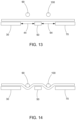
- FIG. 13 is a schematic end view like that seen in FIG. 3 , now of alternate features of the tri-fold machine and process;
- FIG. 14 is a schematic end view of that seen in FIG. 13 , and with the pair of longitudinal bars in an alternate lowered position; and,
- FIGS. 15 and 16 are like that seen in FIG. 11 , now of alternate features of the tri-fold machine and process.
- vantage point A is employed in FIGS. 1 and 2 .
- vantage point B is employed to give meaning to the left and right orientation of machine parts.
- the opposite orientation could be easily employed and is interchangeable therewith by flipping from the B vantage point to the A vantage point, if desired. Accordingly, from the B vantage point, there is a left-side horizontal conveyor 30 next to a middle conveyor 50 .
- a left longitudinal gap 52 is formed between the left-side horizontal conveyor 30 and the middle conveyor 50 .
- a right-side horizontal conveyor 70 is next to an opposite side 54 ( FIG. 2 ) of the middle conveyor with a right longitudinal gap 58 formed between the right-side horizontal conveyor 70 and the middle conveyor 50 .
- An upper surface 32 , 72 of each of the left-side horizontal conveyor and the right-side horizontal conveyor defines a horizontal plane 34 .
- the left-side horizontal conveyor 30 and the right-side horizontal conveyor 70 preferably, each have a movable surface 36 , 76 to locate the material 20 into a material folding position (as seen in FIG. 3 ) relative to a left longitudinal bar 90 and a right longitudinal bar 100 .
- Surfaces 36 , 76 , and also preferably 56 could be belts, rollers, forced air or other conventional mechanical transport mechanisms, as can be arranged to form a horizontal surface or horizontal-like surface. Movable surfaces 36 , 56 , 76 , can move in direction of travel 13 to receive compressed material 12 from a conventional upstream conveyor 12 . Conveyor 12 itself, or prior to material 20 arriving there, transformed a conventional compressible product, like a mattress, into the compressed high expansion force material 20 using conventional compression equipment and techniques. Thus, prior to folding, the material 20 is positionable on the left-side conveyor and the right-side conveyor, preferably with each of the left longitudinal bar and the right longitudinal bar overlying a middle portion 22 of the material ( FIG. 3 ).
- the left longitudinal bar 90 is operable between (i) a raised position 92 where a bottom surface 94 is spaced from and above the horizontal plane 34 ( FIG. 3 ) as well as spaced from the top surface 24 , and (ii) a lowered position 96 where the bottom surface 94 is located closer to the horizontal plane 34 than in the raised position.
- the right longitudinal bar 100 is also operable between (i) a raised position 102 where a bottom surface 104 is spaced from and above the horizontal plane 34 ( FIG. 3 ) as well as spaced from the top surface 24 , and (ii) a lowered position 106 where the bottom surface 104 is located closer to the horizontal plane 34 than in the raised position.
- the left longitudinal bar and the right longitudinal bar are coupled together, for example by a cross bar 108 , such that each longitudinal bar 90 , 100 is movable between the raised position and the lowered position simultaneously, i.e., in a vertical direction relative to the horizontal surfaces 32 , 72 .
- This can be accomplished, for example, by a bar raising linkage 110 that also extends below the machine folding surface and uses a conventional mechanism to move the bars 90 , 100 up and down as desired.
- the bottom surface 94 , 104 of at least one of the left longitudinal bar and the right longitudinal bar is equal with to below the horizontal plane when in the lowered position (e.g., FIGS.
- both surfaces 94 , 104 can be so located in the lowered position simultaneously. That is, preferably, bottom surface(es) 94 , 104 is/are in contact with top surface 24 of the material when the longitudinal bar 90 , 100 is in the lowered position. Still more preferably in this regard, at least one of the longitudinal bars 90 , 100 press(es) the material into the respective longitudinal gaps 52 , 58 when the longitudinal bar(s) 30 , 70 is in the lowered position.
- left longitudinal bar 90 is sized to fit completely in the left longitudinal gap 52
- right longitudinal bar 100 sized to fit completely in the right longitudinal gap 58 , and this occurs when material 20 is not present.
- the longitudinal bars 90 , 100 can be adjustable, in a horizontal direction 98 ( FIGS. 11 and 12 ), as well as the vertical direction (i.e., positioned between raised positions 92 , 102 and lowered positions 96 , 106 and anywhere in between). That is, preferably: (i) one of the bars 90 or 100 can be fixed relative the conveyors 30 , 50 , 70 and the other of the bars 100 or 90 adjustable relative to that bar, or (ii) both bars 90 and 100 can be adjustable relative to the conveyors 30 , 50 , 70 and each other bar 100 , 90 , respectively.
- the middle portion width in horizontally direction 98 is determined by the horizontal spacing of the bars 90 , 100 , and so can make the middle be a true one-third of the overall width of material 20 , or something less or greater than that, as desired.
- the bars 90 , 100 while adjustable as discussed, are temporarily fixed relative to one another when being used to fold the material around the bars.
- one of the bars 90 , 100 may be movable relative to the other bar 100 , 90 , even during folding, as may be desired to further assist with the folding process, especially in such a tri-fold configuration.
- the conveyors 30 , 50 , 70 can also be adjustable in horizontal direction 44 (i.e., for conveyors 30 and 50 each individually, as well as relative to one another) and/or in horizontal direction 64 (i.e., for conveyors 50 and 70 each individually, as well as relative to one another).
- one of the bars 90 can be fixed relative the other bar 100 , and bar 100 can be positioned further to the right relative to the bar positioning in all the prior FIGs, and then in concert with this further right position so can one or both of conveyors 50 and 70 be positioned further to the right relative to the conveyor positioning in all the prior FIGs.
- both conveyors are so moved to the right a sufficient distance to cause the right longitudinal gap between conveyors 50 and 70 to be centered under bar 100 (but an off-set positioning of this gap can be used too, if desired).
- this enables even more tri-fold configuration sizes of middle portion 22 of the material relative to right side 26 and left side 28 , when material 20 is folded.
- the middle portion width in horizontally direction 98 is determined by the horizontal spacing of the bars 90 , 100 , and so can make the middle be a true one-third of the overall width of material 20 , or something less or greater than that, as desired.
- restriction force 130 can be employed coinciding with distal end 62 of middle conveyor 50 and respective ends of the bars 90 , 100 .
- the force 130 acts to push the distal ends of bars 90 , 100 outward, or at least prevent the distal ends of bars 90 , 100 from being pressed inward of the span represented by the ends of the arrows representing force 130 .
- the proximal end 60 that corresponds to bars 90 , 100 and their coupling together 108 acts to hold bars 90 , 100 apart as desired (or not, as described elsewhere for the spacing of bars 90 , 100 in general) during the folding process.
- restriction force 130 can be employed at the opposite end of the bars 90 , 100 to help hold them at a desired spaced apart location (or not, as described elsewhere for the spacing of bars 90 , 100 in general) during the folding process, preferably to help form a more crisp fold along the entire length of the folded material 20 .
- force 130 could be achieved by restriction plates 132 that prevent the inward toward-each-other movement of bars 90 , 100 during the folding process. Plates 132 can selectively move up and down to assist holding apart bars 90 , 100 before and during folding, and then move down ( FIG. 16 ) to get out of the way of the advancing folded material 20 when time for it to move into the roll forming stage of the packaging process.
- plates 132 could be a single horizontal plate (not shown) that has horizontal pins (not shown) projecting orthogonally therefrom toward the ends of bars 90 , 100 and bars 90 , 100 could have receiving holes (not shown) in the distal ends of bars 90 , 100 to receive the pins and thus hold distal ends of bars 90 , 100 apart when desired.
- other mechanical structures could be employed to attain the restriction force 130 , when desired, as would be known to one of ordinary skill in the art in combination with the innovative teachings herein.
- the tri-fold machine 10 also includes the right-side conveyor 70 that is movable between a horizontal home position 78 and a folding position 80 , as seen in progression of FIGS. 7 to 8 A inclusive, via a travel path depicted by the dotted line arrows(s) in each of FIGS. 8 and 8 A .
- the folding position 80 is where the right-side conveyor is located above and extending over the middle conveyor with at least some overlying overlap of conveyor 70 over conveyor 50 . As seen in FIGS. 8 and 8 A , there is complete overlap of conveyor 70 over conveyor 50 .
- the folding position 80 of the right-side conveyor can be the right-side conveyor located above and extending over the right longitudinal bar 100 , completely over as seen in the figures, or even just partially over though not specifically seen in the figures. Further in this regard, more preferably, the folding position 80 of the right-side conveyor can be the right-side conveyor located above and also extending over the left longitudinal bar 90 , as seen in FIGS. 8 and 8 A with right-side conveyor 70 located above and extending over the left longitudinal bar 90 , though only over a portion of bar 90 .
- the folding position 80 of the right-side conveyor can be a left edge 82 of the right-side conveyor located above and extending over the middle conveyor 50 , as seen in FIG. 8 .
- the movement of conveyor 70 can be first in a purely vertical direction (as represented by the up dotted arrow in FIG. 8 ), and then in a purely horizontal direction (as represented by the left pointing dotted arrow in FIG. 8 ).
- the movement of conveyor 70 can be first in a slight vertical direction (as in FIG. 7 ), and then in a curved vertical and horizontal direction (represented by the curved dotted arrow in FIG. 8 A ), as first edge 82 pivots around itself allowing the opposite edge of conveyor 70 to flip over and thereby cause the right side 26 of the material 20 to be folded over, as opposed to be pushed up and over in the FIG. 7 to FIG. 8 operation.
- the tri-fold machine 10 also includes the left-side conveyor 30 that is movable between a horizontal home position 38 and a folding position 40 , as seen in progression of FIGS. 5 to 6 A inclusive, via a travel path depicted by the dotted line arrows(s) in each of FIGS. 6 and 6 A .
- the folding position 40 is where the left-side conveyor is located above and extending over the middle conveyor with at least some overlying overlap of conveyor 30 over conveyor 50 . As seen in FIGS. 6 and 6 A , there is complete overlap of conveyor 30 over conveyor 50 .
- the folding position 40 of the left-side conveyor can be the left-side conveyor located above and extending over the left longitudinal bar 90 , completely over as seen in the figures, or even just partially over though not specifically seen in the figures. Further in this regard, more preferably, the folding position 40 of the left-side conveyor can be the left-side conveyor located above and extending over the right longitudinal bar 100 , as seen in FIGS. 6 and 6 A with left-side conveyor 30 located above and extending over the right longitudinal bar 100 , though only a portion of bar 100 .
- the folding position 40 of the left-side conveyor can be a right edge 42 of the left-side conveyor located above and extending over the middle conveyor 50 , as seen in FIG. 6 .
- the movement of conveyor 30 can be first in a purely vertical direction (as represented by the up dotted arrow in FIG. 6 ), and then in a purely horizontal direction (as represented by the right pointing dotted arrow in FIG. 6 ).
- the movement of conveyor 30 can be first in a slight vertical direction (as in FIG. 5 ), and then in a curved vertical and horizontal direction (represented by the curved dotted arrow in FIG. 6 A ), as first edge 42 pivots around itself allowing the opposite edge of conveyor 30 to flip over and thereby cause the left side 28 of the material 20 to be folded over, as opposed to be pushed up and over in the FIG. 5 to FIG. 6 operation.
- a pusher bar(s) 120 can be located adjacent proximal end 60 of the middle conveyor and can be operable to move longitudinally from the proximal end of the middle conveyor to distal end 62 of the middle conveyor. That is, bar 120 can push the material from proximal end 60 toward distal end 62 to advance the material to downstream conveyor 14 .
- Bar 120 uses a conventional mechanism to cause the tri-folded material to be pushed over conveyor 50 and off of bars 90 , 100 in direction 15 ( FIG. 1 ) by linear movement of the same.
- the upper surface of conveyor 14 aids in moving material 20 in direction 15 for further package processing.
- this can include rolling up the tri-folded material into an even more compact package, with equipment and process taught by a conventional roll cage, or preferably, as taught by applicant's U.S. patent application Ser. No. 17/081,639, filed Oct. 27, 2020 and titled: VARIABLE ROLL CAGE MACHINE AND PROCESS.
- the process includes positioning the material 20 on the left-side horizontal conveyor 30 and the right-side horizontal conveyor 70 , with the middle conveyor 50 located between the left-side horizontal conveyor and the right-side horizontal conveyor, and longitudinal gaps 52 , 58 formed on each side of the middle conveyor.
- a next step is pressing the middle portion 22 of the material into at least one longitudinal gap 52 , 58 , and preferably both gaps 52 , 58 .
- Another step is folding the left side 28 of the material over the middle portion 22 of material 20 .
- the right side could be first folded over the middle portion and then the left side folded over the right side that is already folded over the middle portion.
- the process can be where positioning is operating the surface of each of the left-side horizontal conveyor and the right-side horizontal conveyor, as well as the middle conveyor, to locate the material into the material folding position and in FIG. 3 , and then the balance of steps depicted in FIGS. 4 - 10 , inclusive, performed.
- the process can include folding the left side 28 of the material by moving the left-side conveyor 30 from the horizontal home position 38 to the folding position 40 .
- the folding position can be achieved by locating the left-side conveyor above and extending over the middle conveyor, for example, by the travel path in FIG. 6 or 6 A , as described previously.
- folding of the left side 28 of the material includes positioning the right edge 42 of the left-side conveyor above and extending over the middle conveyor, as seen in FIG. 6 .
- conveyor 30 moves, because the material 20 is in a dense, highly compressed state, it tends to be somewhat stiff but also flexible under its own weight when folded. That is, as the left side 28 moves from its position in FIG. 5 to that of FIG. 6 or 6 A , the weight of material 20 tends to flop it over onto itself and hold it there.
- the left side 28 is folded onto the middle 22 before the right side 26 is folded on top, but it could be in reverse too.
- the process can then include folding the right side 26 of the material by moving the right-side conveyor 70 from the horizontal home position 78 to the folding position 80 .
- the folding position can be achieved by locating the right-side conveyor above and extending over the middle conveyor, for example, by the travel path in FIG. 8 or 8 A , as described previously.
- folding of the right side 26 of the material includes positioning the left edge 82 of the right-side conveyor above and extending over the middle conveyor, as seen in FIG. 8 .
- conveyor 70 moves, because material 20 is in a dense, highly compressed state, it tends to be somewhat stiff but also flexible under its own weight when folded. That is, as the right side 26 moves from its position in FIG. 7 to that of FIG. 8 or 8 A , its weight tends to flop it over onto itself and hold it there.
- the process can include operating the pair of spaced apart longitudinal bars 90 , 100 between (i) the raised position 92 , 102 where the bottom surface 94 , 104 is spaced from and above horizontal plane 34 defined by upper surface 32 , 72 of each of the left-side horizontal conveyor and the right-side horizontal conveyor. Additionally, preferably the process as related to bars 90 , 100 , also includes (ii) a lowered position where the bottom surface is located closer to the horizontal plane than in the raised position.
- the lowered position can be pressing the middle portion 22 by moving the pair of spaced apart longitudinal bars 90 , 100 into the fully lowered position and the bottom surfaces 94 , 104 are engaging the top surface 24 of the material adjacent to surfaces 94 , 104 and bars 90 , 100 thereby press the material into the longitudinal gaps 52 , 58 respectively.
- movement of bars, 90 , 100 can be by simultaneously positioning the pair of longitudinal bars together, and particularly so relative to the middle conveyor 50 .
- the process can include releasing the middle portion 22 of the material from being in the longitudinal gaps 52 , 58 formed on each side of the middle conveyor.
- the process can further include holding the right side of the material over the left side of the material, for example by use of conveyor 70 as seen in FIG. 9 .
- the process can include pushing the material 20 from the proximal end 60 of the middle conveyor toward the distal end 62 of the middle conveyor. And, preferably, holding and pushing occur simultaneously.
- Conveyor 14 has an upper surface which travels in direction 15 to help carry the folded material onto the next step in the packaging process, for example, as taught by applicant's U.S. patent application Ser. No. 17/081,639, filed Oct. 27, 2020 and titled: VARIABLE ROLL CAGE MACHINE AND PROCESS.
- the process can include adjusting longitudinal bars 90 , 100 in the horizontal direction 98 ( FIGS. 11 and 12 ). Further, preferably, the process includes fixing at least one of bars 90 or 100 relative to the conveyors 30 , 50 , 70 and adjusting the other of the bars 100 or 90 relative to that bar. Additionally, or alternatively, preferably the process includes adjusting both bars 90 and 100 relative to the conveyors 30 , 50 , 70 and relative to each other bar 100 , 90 . In this way, and without being limited to a theory of understanding, this enables various tri-fold configuration sizes of middle portion 22 of the material relative to right side 26 and left side 28 , when material 20 is folded.
- the middle portion width in horizontally direction 98 is determined by the horizontal spacing of the bars 90 , 100 , and so can make the middle be a true one-third of the overall width of material 20 , or something less or greater than that, as desired.
- the process includes temporarily fixing the bars 90 , 100 relative to one another when being used to fold the material around the bars.
- the process can include moving at least one of the bars 90 , 100 relative to the other bar 100 , 90 , even during folding, as may be desired to further assist with the folding process, especially in such a tri-fold configuration.
- the process can include adjusting one or more of horizontal conveyors 30 , 50 and 70 in the horizontal direction 44 and/or horizontal direction 64 ( FIGS. 13 and 14 ). Further, preferably, the process includes fixing at least one of bars 90 or 100 relative to the conveyors 30 , 50 , 70 and adjusting the other of the bars 100 or 90 relative to that bar. Additionally, or alternatively, preferably the process includes adjusting one or both of conveyors 50 and 70 be positioned a sufficient distance to cause the right longitudinal gap between conveyors 50 and 70 to be centered under bar 100 (but an off-set positioning of this gap can be used too, if desired).
- middle portion width in horizontally direction 98 is determined by the horizontal spacing of the bars 90 , 100 , and so can make the middle be a true one-third of the overall width of material 20 , or something less or greater than that, as desired.
Landscapes
- Engineering & Computer Science (AREA)
- Mechanical Engineering (AREA)
- Folding Of Thin Sheet-Like Materials, Special Discharging Devices, And Others (AREA)
- Manufacturing And Processing Devices For Dough (AREA)
- Auxiliary Devices For And Details Of Packaging Control (AREA)
Priority Applications (2)
| Application Number | Priority Date | Filing Date | Title |
|---|---|---|---|
| US17/565,116 US12258169B2 (en) | 2020-09-29 | 2021-12-29 | Tri-fold machine and process |
| US19/055,908 US12570427B2 (en) | 2020-09-29 | 2025-02-18 | Tri-fold machine and process |
Applications Claiming Priority (3)
| Application Number | Priority Date | Filing Date | Title |
|---|---|---|---|
| US202063085052P | 2020-09-29 | 2020-09-29 | |
| PCT/US2021/028873 WO2022071995A1 (fr) | 2020-09-29 | 2021-04-23 | Machine à trois plis et processus |
| US17/565,116 US12258169B2 (en) | 2020-09-29 | 2021-12-29 | Tri-fold machine and process |
Related Parent Applications (1)
| Application Number | Title | Priority Date | Filing Date |
|---|---|---|---|
| PCT/US2021/028873 Continuation-In-Part WO2022071995A1 (fr) | 2020-09-29 | 2021-04-23 | Machine à trois plis et processus |
Related Child Applications (1)
| Application Number | Title | Priority Date | Filing Date |
|---|---|---|---|
| US19/055,908 Division US12570427B2 (en) | 2020-09-29 | 2025-02-18 | Tri-fold machine and process |
Publications (2)
| Publication Number | Publication Date |
|---|---|
| US20220119145A1 US20220119145A1 (en) | 2022-04-21 |
| US12258169B2 true US12258169B2 (en) | 2025-03-25 |
Family
ID=80951622
Family Applications (2)
| Application Number | Title | Priority Date | Filing Date |
|---|---|---|---|
| US17/565,116 Active 2042-08-15 US12258169B2 (en) | 2020-09-29 | 2021-12-29 | Tri-fold machine and process |
| US19/055,908 Active US12570427B2 (en) | 2020-09-29 | 2025-02-18 | Tri-fold machine and process |
Family Applications After (1)
| Application Number | Title | Priority Date | Filing Date |
|---|---|---|---|
| US19/055,908 Active US12570427B2 (en) | 2020-09-29 | 2025-02-18 | Tri-fold machine and process |
Country Status (5)
| Country | Link |
|---|---|
| US (2) | US12258169B2 (fr) |
| EP (1) | EP4222062A4 (fr) |
| CA (1) | CA3196161A1 (fr) |
| MX (1) | MX2023003555A (fr) |
| WO (1) | WO2022071995A1 (fr) |
Cited By (1)
| Publication number | Priority date | Publication date | Assignee | Title |
|---|---|---|---|---|
| US20210390498A1 (en) * | 2018-11-01 | 2021-12-16 | C3.Ai, Inc. | Systems and methods for inventory management and optimization |
Families Citing this family (3)
| Publication number | Priority date | Publication date | Assignee | Title |
|---|---|---|---|---|
| CN116902330B (zh) * | 2023-09-11 | 2023-11-17 | 苏州骏奇业包装科技有限公司 | 一种液体盒中袋产品输送装置 |
| TR2023011319A1 (tr) * | 2023-09-12 | 2025-03-21 | Elektroteks Elektronik Tekstil Sanayi Ve Ticaret Anonim Sirketi | Yatak paketleme hattinda kullanilmak üzere bi̇r katlama üni̇tesi̇ |
| EP4603402A1 (fr) * | 2024-02-15 | 2025-08-20 | FillMatic Polsterindustriemaschinen GmbH | Appareil de pliage |
Citations (14)
| Publication number | Priority date | Publication date | Assignee | Title |
|---|---|---|---|---|
| US2362976A (en) | 1942-03-03 | 1944-11-21 | Prosperity Co Inc | Garment folding machine |
| FR2861693A1 (fr) * | 2003-10-31 | 2005-05-06 | Onrev | Procede et dispositif de pliage et de conditionnement de matelas |
| US7059101B2 (en) | 2003-09-25 | 2006-06-13 | Foamex L.P. | Method for packaging bedding assembly |
| JP2009213554A (ja) | 2008-03-07 | 2009-09-24 | Purex:Kk | 衣類折畳み機 |
| US20110266188A1 (en) * | 2010-02-15 | 2011-11-03 | Illinois Tool Works Inc. | Form fill seal packaging method and apparatus for compressible goods |
| US8333279B2 (en) | 2008-09-11 | 2012-12-18 | Simple Container Solutions, Inc. | Expandable insulated packaging |
| US8496637B2 (en) | 2007-06-18 | 2013-07-30 | The Procter & Gamble Company | Tri-folded disposable absorbent article, packaged absorbent article, and array of packaged absorbent articles with substantially continuously distributed absorbent particulate polymer material |
| US20150203221A1 (en) | 2014-01-10 | 2015-07-23 | C3 Corporation | System and method for packaging a foam product |
| US20160304231A1 (en) | 2015-02-20 | 2016-10-20 | Comfort Revolution, LLC | Methods of manufacturing, compressing, rolling, folding and packaging mattresses |
| KR101784936B1 (ko) | 2016-02-15 | 2017-10-12 | 권오기 | 의류 자동 접이장치 |
| KR101860373B1 (ko) * | 2017-05-22 | 2018-05-24 | 주식회사 젠티스 | 매트리스 패킹장치 |
| BR102018072864A2 (pt) * | 2018-11-07 | 2020-05-26 | Sidney Gonçalves Da Silva | Processo para embalagem de colchões de molas em caixas de papelão |
| CN111605837A (zh) * | 2020-05-27 | 2020-09-01 | 绍兴汉工智能科技有限公司 | 一种布匹折叠装置 |
| CN110053837B (zh) | 2019-04-15 | 2020-09-08 | 广州市联柔机械设备有限公司 | 软垫输送装置、方法及软垫卷压包装设备、方法 |
Family Cites Families (5)
| Publication number | Priority date | Publication date | Assignee | Title |
|---|---|---|---|---|
| IT1391403B1 (it) * | 2008-09-10 | 2011-12-23 | C M C Srl | Dispositivo per la rotazione orizzontale di articoli piani alimentati lungo una linea di trasporto |
| US8312576B1 (en) * | 2011-09-19 | 2012-11-20 | Zinus, Inc. | Sturdy, collapsible, folding mattress support having the appearance of a box spring |
| CN203921388U (zh) * | 2014-07-08 | 2014-11-05 | 江苏迎阳无纺机械有限公司 | 被子折叠机 |
| CN207536277U (zh) * | 2017-08-30 | 2018-06-26 | 桐乡市佳韵纺织品有限公司 | 一种全自动叠被流水线 |
| US11136154B2 (en) * | 2017-09-22 | 2021-10-05 | Atlanta Attachment Company | Packaging machine for bedding products |
-
2021
- 2021-04-23 WO PCT/US2021/028873 patent/WO2022071995A1/fr not_active Ceased
- 2021-04-23 EP EP21876143.5A patent/EP4222062A4/fr active Pending
- 2021-04-23 CA CA3196161A patent/CA3196161A1/fr active Pending
- 2021-04-23 MX MX2023003555A patent/MX2023003555A/es unknown
- 2021-12-29 US US17/565,116 patent/US12258169B2/en active Active
-
2025
- 2025-02-18 US US19/055,908 patent/US12570427B2/en active Active
Patent Citations (16)
| Publication number | Priority date | Publication date | Assignee | Title |
|---|---|---|---|---|
| US2362976A (en) | 1942-03-03 | 1944-11-21 | Prosperity Co Inc | Garment folding machine |
| US7059101B2 (en) | 2003-09-25 | 2006-06-13 | Foamex L.P. | Method for packaging bedding assembly |
| FR2861693A1 (fr) * | 2003-10-31 | 2005-05-06 | Onrev | Procede et dispositif de pliage et de conditionnement de matelas |
| FR2861693B1 (fr) | 2003-10-31 | 2006-03-10 | Onrev | Procede et dispositif de pliage et de conditionnement de matelas |
| US8496637B2 (en) | 2007-06-18 | 2013-07-30 | The Procter & Gamble Company | Tri-folded disposable absorbent article, packaged absorbent article, and array of packaged absorbent articles with substantially continuously distributed absorbent particulate polymer material |
| JP2009213554A (ja) | 2008-03-07 | 2009-09-24 | Purex:Kk | 衣類折畳み機 |
| US8333279B2 (en) | 2008-09-11 | 2012-12-18 | Simple Container Solutions, Inc. | Expandable insulated packaging |
| US20110266188A1 (en) * | 2010-02-15 | 2011-11-03 | Illinois Tool Works Inc. | Form fill seal packaging method and apparatus for compressible goods |
| US20150203221A1 (en) | 2014-01-10 | 2015-07-23 | C3 Corporation | System and method for packaging a foam product |
| US20160304231A1 (en) | 2015-02-20 | 2016-10-20 | Comfort Revolution, LLC | Methods of manufacturing, compressing, rolling, folding and packaging mattresses |
| KR101784936B1 (ko) | 2016-02-15 | 2017-10-12 | 권오기 | 의류 자동 접이장치 |
| KR101860373B1 (ko) * | 2017-05-22 | 2018-05-24 | 주식회사 젠티스 | 매트리스 패킹장치 |
| BR102018072864A2 (pt) * | 2018-11-07 | 2020-05-26 | Sidney Gonçalves Da Silva | Processo para embalagem de colchões de molas em caixas de papelão |
| CN110053837B (zh) | 2019-04-15 | 2020-09-08 | 广州市联柔机械设备有限公司 | 软垫输送装置、方法及软垫卷压包装设备、方法 |
| US20220144462A1 (en) * | 2019-04-15 | 2022-05-12 | Guangzhou Lianrou Machinery & Equipment Co., Ltd. | Cushion conveying device and method, and cushion rolling packaging apparatus and method |
| CN111605837A (zh) * | 2020-05-27 | 2020-09-01 | 绍兴汉工智能科技有限公司 | 一种布匹折叠装置 |
Non-Patent Citations (11)
| Title |
|---|
| Atlanta Attachment Co, "1390HCB—Automatic Mattress Packaging with Compression, Single Fold & Roll Pack" YouTube video, retrieved from the internet on or before Sep. 28, 2020 at https://www.youtube.com/watch?v=sO0Zf8gQ3UE, 43 pages filed herewith. |
| C3 Corporation, description by Applicant of its bi-fold machine and process for making compressed rolled up product from high expansion force material, like a mattress, the machine and process has been available to the public at least as early as Sep. 28, 2020, 1 page filed herewith. |
| Elektroteks, "ET-ROLL-210 Mattress Compress and Roll Pack Machine with Manual Folding" YouTube video, retrieved from the internet on or before Sep. 28, 2020 at https://www.youtube.com/watch?v=tjx4MRP63uE, 35 pages filed herewith. |
| Hanvey Huang, "Automatic Mattress Folding Compress Roll Pack Machine" YouTube video, retrieved from the Internet on or before Sep. 28, 2020, 46 pages filed herewith. |
| Machine translation of BR-102018072864-A2 (Year: 2020). * |
| Machine translation of CN-111605837-A (Year: 2020). * |
| Machine translation of FR-2861693-A1 (Year: 2005). * |
| Machine translation of KR-101860373-B1 (Year: 2018). * |
| Made-in-China, "Ng-22RS Fully Automatic Mattress Compression Rolling and Folding Wrapping Packing Mattress Machine", retrieved from the internet on or before Sep. 28, 2020 at https://cnnaigu.en.made-in-china.com/product/iZDaPHsugAkG/China-Ng-22RS-Fully-Automatic-Mattress-Compression-Rolling-and-Folding-Wrapping-Packing-Mattres-Machine.html, 11 pages filed herewith. |
| Mattress Clarity, "How To Compress, Fold And Roll Up A Memory Foam Mattress—Bed In a Box Secrets!" YouTube video, retrieved from the internet on or before Sep. 28, 2020 at https://www.youtube.com/watch?v=6ZDGDIrXepg, 50 pages filed herewith. |
| Search Report & Written Opinion for PCT Patent Application No. PCT/US2021/028873, "Tri-Fold Machine and Process" dated Aug. 6, 2021, 12 pages filed herewith. |
Cited By (2)
| Publication number | Priority date | Publication date | Assignee | Title |
|---|---|---|---|---|
| US20210390498A1 (en) * | 2018-11-01 | 2021-12-16 | C3.Ai, Inc. | Systems and methods for inventory management and optimization |
| US12555069B2 (en) * | 2018-11-01 | 2026-02-17 | C3.Ai, Inc. | Systems and methods for inventory management and optimization |
Also Published As
| Publication number | Publication date |
|---|---|
| US20250187775A1 (en) | 2025-06-12 |
| US20220119145A1 (en) | 2022-04-21 |
| US12570427B2 (en) | 2026-03-10 |
| CA3196161A1 (fr) | 2022-04-07 |
| MX2023003555A (es) | 2023-06-07 |
| EP4222062A4 (fr) | 2025-04-23 |
| WO2022071995A1 (fr) | 2022-04-07 |
| EP4222062A1 (fr) | 2023-08-09 |
Similar Documents
| Publication | Publication Date | Title |
|---|---|---|
| US12570427B2 (en) | Tri-fold machine and process | |
| US7536844B2 (en) | Device and process for packaging tyres | |
| US8950164B2 (en) | Packaging for mattresses and apparatus for providing the packaging | |
| US6298510B1 (en) | Roll packed bedding products | |
| US20020124531A1 (en) | Method of packaging spring units | |
| JPH0656105A (ja) | カートン製造装置 | |
| US6467239B2 (en) | Method of packaging spring units | |
| US20240025583A1 (en) | Systems for packaging stacks of bags | |
| CN107776996A (zh) | 将床垫包装成双螺旋卷的方法 | |
| US10858130B2 (en) | Packaging apparatus with evacuation assembly and packaging process | |
| KR102552989B1 (ko) | 웹 재료를 롤로 패키징하기 위한 조립 시스템 및 방법 | |
| JP4373701B2 (ja) | ガゼット包装機 | |
| JP5263661B2 (ja) | ケース組立装置 | |
| US11535411B2 (en) | Folding apparatus | |
| US20240359843A1 (en) | Pipe compression equipment | |
| JPH0385232A (ja) | 圧縮物品をパックするための方法及び装置 | |
| KR102486529B1 (ko) | 자동 띠지 결합장치 | |
| US11787655B2 (en) | Variable roll cage machine and process | |
| JP6826120B2 (ja) | 袋の襞部を成形するための装置 | |
| JP7842347B2 (ja) | 集積装置 | |
| JP7629150B1 (ja) | 反転搬送手段 | |
| IT201900005694A1 (it) | Metodo di piegatura di un materasso e relativa macchina. | |
| JPS6317685B2 (fr) | ||
| JP6598398B2 (ja) | 包装方法 | |
| WO2017149485A1 (fr) | Appareil et procédé pour emballage de matelas, et matelas |
Legal Events
| Date | Code | Title | Description |
|---|---|---|---|
| FEPP | Fee payment procedure |
Free format text: ENTITY STATUS SET TO UNDISCOUNTED (ORIGINAL EVENT CODE: BIG.); ENTITY STATUS OF PATENT OWNER: SMALL ENTITY |
|
| FEPP | Fee payment procedure |
Free format text: ENTITY STATUS SET TO SMALL (ORIGINAL EVENT CODE: SMAL); ENTITY STATUS OF PATENT OWNER: SMALL ENTITY |
|
| AS | Assignment |
Owner name: C3 CORPORATION, WISCONSIN Free format text: ASSIGNMENT OF ASSIGNORS INTEREST;ASSIGNORS:VAN DE HEY, JOSEPH F.;ZIRBEL, ALEX M.;KUFFEL, ALEX N.;AND OTHERS;REEL/FRAME:059226/0846 Effective date: 20220223 Owner name: C3 CORPORATION, UNITED STATES Free format text: ASSIGNMENT OF ASSIGNORS INTEREST;ASSIGNORS:VAN DE HEY, JOSEPH F.;ZIRBEL, ALEX M.;KUFFEL, ALEX N.;AND OTHERS;REEL/FRAME:059225/0721 Effective date: 20210422 |
|
| STPP | Information on status: patent application and granting procedure in general |
Free format text: DOCKETED NEW CASE - READY FOR EXAMINATION |
|
| STPP | Information on status: patent application and granting procedure in general |
Free format text: NON FINAL ACTION MAILED |
|
| STPP | Information on status: patent application and granting procedure in general |
Free format text: RESPONSE TO NON-FINAL OFFICE ACTION ENTERED AND FORWARDED TO EXAMINER |
|
| STPP | Information on status: patent application and granting procedure in general |
Free format text: NON FINAL ACTION MAILED |
|
| STPP | Information on status: patent application and granting procedure in general |
Free format text: NON FINAL ACTION MAILED |
|
| STPP | Information on status: patent application and granting procedure in general |
Free format text: RESPONSE TO NON-FINAL OFFICE ACTION ENTERED AND FORWARDED TO EXAMINER |
|
| STPP | Information on status: patent application and granting procedure in general |
Free format text: NOTICE OF ALLOWANCE MAILED -- APPLICATION RECEIVED IN OFFICE OF PUBLICATIONS |
|
| STPP | Information on status: patent application and granting procedure in general |
Free format text: PUBLICATIONS -- ISSUE FEE PAYMENT VERIFIED |
|
| STCF | Information on status: patent grant |
Free format text: PATENTED CASE |
|
| CC | Certificate of correction |