US12283848B2 - Rotor for rotary electric machine - Google Patents
Rotor for rotary electric machine Download PDFInfo
- Publication number
- US12283848B2 US12283848B2 US17/926,941 US202117926941A US12283848B2 US 12283848 B2 US12283848 B2 US 12283848B2 US 202117926941 A US202117926941 A US 202117926941A US 12283848 B2 US12283848 B2 US 12283848B2
- Authority
- US
- United States
- Prior art keywords
- magnet
- rotor
- radial direction
- section
- magnetic poles
- Prior art date
- Legal status (The legal status is an assumption and is not a legal conclusion. Google has not performed a legal analysis and makes no representation as to the accuracy of the status listed.)
- Active, expires
Links
Images




Classifications
-
- H—ELECTRICITY
- H02—GENERATION; CONVERSION OR DISTRIBUTION OF ELECTRIC POWER
- H02K—DYNAMO-ELECTRIC MACHINES
- H02K1/00—Details of the magnetic circuit
- H02K1/06—Details of the magnetic circuit characterised by the shape, form or construction
- H02K1/22—Rotating parts of the magnetic circuit
- H02K1/27—Rotor cores with permanent magnets
- H02K1/2706—Inner rotors
- H02K1/272—Inner rotors the magnetisation axis of the magnets being perpendicular to the rotor axis
- H02K1/274—Inner rotors the magnetisation axis of the magnets being perpendicular to the rotor axis the rotor consisting of two or more circumferentially positioned magnets
- H02K1/2753—Inner rotors the magnetisation axis of the magnets being perpendicular to the rotor axis the rotor consisting of two or more circumferentially positioned magnets the rotor consisting of magnets or groups of magnets arranged with alternating polarity
- H02K1/276—Magnets embedded in the magnetic core, e.g. interior permanent magnets [IPM]
- H02K1/2766—Magnets embedded in the magnetic core, e.g. interior permanent magnets [IPM] having a flux concentration effect
-
- H—ELECTRICITY
- H02—GENERATION; CONVERSION OR DISTRIBUTION OF ELECTRIC POWER
- H02K—DYNAMO-ELECTRIC MACHINES
- H02K1/00—Details of the magnetic circuit
- H02K1/06—Details of the magnetic circuit characterised by the shape, form or construction
- H02K1/22—Rotating parts of the magnetic circuit
- H02K1/27—Rotor cores with permanent magnets
- H02K1/2706—Inner rotors
- H02K1/272—Inner rotors the magnetisation axis of the magnets being perpendicular to the rotor axis
- H02K1/274—Inner rotors the magnetisation axis of the magnets being perpendicular to the rotor axis the rotor consisting of two or more circumferentially positioned magnets
- H02K1/2753—Inner rotors the magnetisation axis of the magnets being perpendicular to the rotor axis the rotor consisting of two or more circumferentially positioned magnets the rotor consisting of magnets or groups of magnets arranged with alternating polarity
- H02K1/276—Magnets embedded in the magnetic core, e.g. interior permanent magnets [IPM]
-
- H—ELECTRICITY
- H02—GENERATION; CONVERSION OR DISTRIBUTION OF ELECTRIC POWER
- H02K—DYNAMO-ELECTRIC MACHINES
- H02K2201/00—Specific aspects not provided for in the other groups of this subclass relating to the magnetic circuits
- H02K2201/03—Machines characterised by aspects of the air-gap between rotor and stator
-
- H—ELECTRICITY
- H02—GENERATION; CONVERSION OR DISTRIBUTION OF ELECTRIC POWER
- H02K—DYNAMO-ELECTRIC MACHINES
- H02K2213/00—Specific aspects, not otherwise provided for and not covered by codes H02K2201/00 - H02K2211/00
- H02K2213/03—Machines characterised by numerical values, ranges, mathematical expressions or similar information
-
- Y—GENERAL TAGGING OF NEW TECHNOLOGICAL DEVELOPMENTS; GENERAL TAGGING OF CROSS-SECTIONAL TECHNOLOGIES SPANNING OVER SEVERAL SECTIONS OF THE IPC; TECHNICAL SUBJECTS COVERED BY FORMER USPC CROSS-REFERENCE ART COLLECTIONS [XRACs] AND DIGESTS
- Y02—TECHNOLOGIES OR APPLICATIONS FOR MITIGATION OR ADAPTATION AGAINST CLIMATE CHANGE
- Y02T—CLIMATE CHANGE MITIGATION TECHNOLOGIES RELATED TO TRANSPORTATION
- Y02T10/00—Road transport of goods or passengers
- Y02T10/60—Other road transportation technologies with climate change mitigation effect
- Y02T10/64—Electric machine technologies in electromobility
Definitions
- the present disclosure relates to a rotor for a rotary electric machine.
- a technique includes a rotor core having magnet holes on the inner side in the radial direction and magnet holes on the outer side in the radial direction for each of the magnetic poles and that widens a q-axis magnetic path entrance/exit portion between the magnet holes on the inner side in the radial direction and the magnet holes on the outer side in the radial direction.
- a rotor core having magnet holes on the inner side in the radial direction and magnet holes on the outer side in the radial direction for each of the magnetic poles often includes bridge portions connecting sections partitioned by the magnet holes and the like.
- the bridge portions may cause inconveniences such as leakage of magnetic flux passing therethrough (and decrease in torque accompanying the leakage). Therefore, it is desirable to reduce the width of the bridge portion in terms of reducing such inconveniences. However, if the width of the bridge portion is reduced, a problem of stress is likely to occur.
- an object of the present disclosure is to reduce the stress on the bridge portion in the rotor for a rotary electric machine having, in a rotor core, magnet holes on the inner side in the radial direction and magnet holes on the outer side in the radial direction.
- a rotor for a rotary electric machine having a plurality of magnetic poles along the circumferential direction includes: a rotor core provided with a first magnet hole on an outer side in a radial direction and a second magnet hole on an inner side in the radial direction for each of the magnetic poles; and a plurality of permanent magnets provided in the first magnet hole and the second magnet hole and forming the magnetic poles.
- the rotor core includes a first section provided radially outside of the first magnet hole, a second section extending between the first magnet hole and the second magnet hole and having opposite ends in the circumferential direction that extend to an outer peripheral surface of the rotor core, a third section extending radially inside of the second magnet hole and having opposite ends in the circumferential direction that extend to the outer peripheral surface of the rotor core, a first bridge portion that connects the second section and the first section and forms a part of the outer peripheral surface of the rotor core, and a second bridge portion that connects the third section and the second section and forms a part of the outer peripheral surface of the rotor core.
- the first bridge portion is disposed radially inside of the second bridge portion.
- FIG. 1 is a sectional view schematically showing a cross-sectional structure of a motor according to an embodiment.
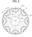
- FIG. 2 is a cross-sectional view of a rotor 30 (cross-sectional view taken along a plane perpendicular to an axial direction).
- FIG. 3 is an enlarged cross-sectional view of a part of the rotor according to the present embodiment.
- FIG. 4 is an explanatory diagram of a rotor according to a comparative example.
- FIG. 5 A is an explanatory diagram of a stress reduction principle according to the present embodiment.
- FIG. 5 B is an explanatory diagram of a force generated in the rotor according to the comparative example used for comparison.
- FIG. 6 is an enlarged cross-sectional view of a part of a rotor according to a first modification.
- FIG. 7 is an enlarged cross-sectional view of a part of a rotor according to a second modification.
- FIG. 1 is a sectional view schematically showing a sectional structure of a motor 1 (an example of a rotary electric machine) according to an embodiment.
- FIG. 2 is a cross-sectional view of a rotor 30 (cross-sectional view taken along a plane perpendicular to the axial direction).
- reference signs may be given only to part of a plurality of sections having the same attributes.
- FIG. 1 shows a rotation axis 12 of the motor 1 .
- the axial direction refers to a direction in which a rotation axis (rotation center) 12 of the motor 1 extends
- the radial direction refers to a radial direction centered on the rotation axis 12 . Therefore, the outer side in the radial direction refers to a side away from the rotation axis 12 , and the inner side in the radial direction refers to a side toward the rotation axis 12 .
- the circumferential direction corresponds to a rotation direction around the rotation axis 12 .
- the motor 1 may be a motor for driving a vehicle, which is used in a hybrid vehicle or an electric vehicle, for example. However, the motor 1 may be a motor used for any other purpose.
- the motor 1 is of an inner rotor type, and a stator 21 is provided so as to surround the outer side of the rotor 30 in the radial direction.
- the outer side of the stator 21 in the radial direction is fixed to a motor housing 10 .
- the stator 21 includes a stator core 211 composed of laminated steel sheets made of a magnetic body and having an annular shape, for example, and a plurality of slots (not shown) on which a coil 22 is wound is provided on the inner side of the stator core 211 in the radial direction.
- the rotor 30 is disposed on the inner side of the stator 21 in the radial direction.
- the rotor 30 includes a rotor core 32 , a rotor shaft 34 , end plates 35 A, 35 B, and permanent magnets 61 , 62 .
- the rotor core 32 is fixed to the surface of the rotor shaft 34 on the outer side in the radial direction, and rotates together with the rotor shaft 34 .
- the rotor core 32 has a shaft hole 320 (see FIG. 2 ), and the rotor shaft 34 is fitted in the shaft hole 320 .
- the rotor core 32 may be fixed to the rotor shaft 34 by shrink fitting, press fitting, or the like.
- the rotor core 32 may be coupled to the rotor shaft 34 by key coupling or spline coupling.
- the rotor shaft 34 is rotatably supported by the motor housing 10 via bearings 14 a , 14 b .
- the rotor shaft 34 defines the rotation axis 12 of the motor 1 .
- the rotor core 32 is composed of, for example, laminated steel sheets made of a magnetic body and having an annular shape.
- the permanent magnets 61 , 62 (see FIG. 2 ) are embedded in the rotor core 32 . That is, the rotor core 32 has magnet holes 321 , 322 (see FIG. 2 ) passing through the rotor core 32 in the axial direction, and the permanent magnets 61 , 62 are inserted and fixed in the magnet holes 321 , 322 .
- the rotor core 32 may be made of a green compact obtained by compressing and solidifying magnetic powder.
- the rotor core 32 is designed in a circular shape having a first radius r 1 , and the outer peripheral surface of the rotor core 32 includes a portion having the first radius r 1 (an outer peripheral surface portion 328 B, a portion 328 C, and the like, which will be described later).
- the outer peripheral surface of the rotor core 32 has the first radius r 1 except for recesses 70 described later.
- the circular shape of the rotor core 32 does not have to be a perfect circle, and may be, for example, a circular shape having a notch in a part thereof.
- the rotor core 32 has a rotationally symmetric form centered on the rotation axis 12 when viewed in the axial direction.
- the rotor core 32 has a form in which the permanent magnets 61 , 62 of respective sets overlap each time the rotor core 32 rotates 45 degrees around the rotation axis 12 .
- the permanent magnets 61 , 62 may be made of neodymium or the like.
- the permanent magnets 61 , 62 that are two types of permanent magnets are arranged such that each pair of permanent magnets 61 and each pair of permanent magnets 62 respectively form a substantially V-shape (substantially V-shape with its outer side in the radial direction open) when viewed in the axial direction.
- a common magnetic pole is formed between the two permanent magnets 61 in a pair and between the two permanent magnets 62 in a pair.
- the permanent magnets 61 , 62 are arranged in such a manner that S poles and N poles appear alternately in the circumferential direction.
- the number of magnetic poles is eight, but the number of magnetic poles may be set as appropriate.
- FIG. 1 shows the motor 1 having a specific structure
- the structure of the motor 1 is not limited to such a specific structure.
- the rotor shaft 34 is hollow, but may be solid.
- the end plates 35 A, 35 B have substantially the same outer diameter as the outer diameter of the rotor core 32 and have substantially the same inner diameter as the inner diameter of the rotor core 32 , but are not limited thereto.
- the end plates 35 A, 35 B may have an outer diameter significantly smaller than the outer diameter of the rotor core 32 .
- FIG. 3 is an enlarged view of a portion related to one magnetic pole shown in FIG. 2 .
- the configuration related to one magnetic pole is basically symmetrical with respect to the d-axis (expressed as “d-axis” in English in FIG. 3 ).
- the outer side in the circumferential direction refers to the side away from the d-axis.
- the rotor core 32 has magnet holes 321 on the outer side in the radial direction (hereinafter referred to as “first magnet holes 321 ”) and magnet holes 322 on the inner side in the radial direction (hereinafter referred to as “second magnet holes 322 ”).
- the first magnet holes 321 are provided such that two first magnet holes 321 in a pair forms a substantially V-shape (substantially V-shape with its outer side in the radial direction open). However, in the modification, two first magnet holes 321 in a pair may be formed in a straight line, or a single first magnet hole 321 may be formed in a straight line (a straight line perpendicular to the d-axis).
- the permanent magnet 61 is provided in each first magnet hole 321 .
- a gap may be provided between the first magnet hole 321 and the permanent magnet 61 at both ends of the permanent magnet 61 in the longitudinal direction. The gap may be hollow or may be filled with resin or the like.
- the second magnet holes 322 are provided radially inside of the first magnet holes 321 .
- the second magnet holes 322 are provided such that two second magnet holes 322 in a pair form a substantially V-shape (substantially V-shape with its outer side in the radial direction open).
- the pair of second magnet holes 322 extends over a wider range in the circumferential direction than the pair of first magnet holes 321 .
- the permanent magnet 62 is provided in each second magnet hole 322 .
- a gap may be provided between the second magnet hole 322 and the permanent magnet 62 at both ends of the permanent magnet 62 in the longitudinal direction.
- the gap may be hollow or may be filled with resin or the like.
- the rotor core 32 includes the first magnet holes 321 and the second magnet holes 322 , so that the rotor core 32 has three sections 3211 , 3212 , 3213 that are connected in the radial direction only via bridge portions (hereinafter, also referred to as first site 3211 , second site 3212 , and third site 3213 ).
- the first section 3211 extends radially outside of the first magnet holes 321 .
- the first section 3211 forms a part 328 A of the outer peripheral surface 328 of the rotor core 32 .
- the second section 3212 extends between the second magnet holes 322 and the first magnet holes 321 and has opposite ends in the circumferential direction that extend to the outer peripheral surface 328 of the rotor core 32 .
- the second section 3212 forms a part 328 B of the outer peripheral surface 328 of the rotor core 32 (hereinafter, also referred to as “outer peripheral surface portion 328 B of the second section 3212 ”) on both sides of the first section 3211 in the circumferential direction.
- the second section 3212 forms a magnetic path of a q-axis magnetic flux.
- the q-axis magnetic flux flows between the second magnet holes 322 and the first magnet holes 321 from one end (outer peripheral surface portion 328 B on one side) to the other end (outer peripheral surface portion 328 B on the other side) of the second section 3212 .
- the third section 3213 extends radially inside of the second magnet holes 322 and has opposite ends in the circumferential direction that extend to the outer peripheral surface 328 of the rotor core 32 .
- the third section 3213 forms a part 328 C of the outer peripheral surface 328 of the rotor core 32 on both sides of the second section 3212 in the circumferential direction.
- the mass of the third section 3213 is significantly larger than the mass of the second section 3212
- the mass of the second section 3212 is significantly larger than the mass of the first section 3211 .
- the rotor core 32 includes the three sections 3211 , 3212 , 3213 , so as to have a plurality of bridge portions 41 , 42 , 43 , 44 connecting the three sections 3211 , 3212 , 3213 .
- the bridge portions 41 (hereinafter referred to as “first bridge portions 41 ”) support the first section 3211 with respect to the second section 3212 , on the outer side in the radial direction. That is, the first bridge portions 41 connect the second section 3212 and the first section 3211 and extend in the circumferential direction.
- the first bridge portions 41 in a pair are provided on the opposite sides of the first section 3211 in the circumferential direction (on the outer side in the circumferential direction).
- the first bridge portions 41 extend between the outer peripheral surface 328 of the rotor core 32 and the first magnet holes 321 .
- the first bridge portions 41 extend radially inside of the outermost diameter position of the rotor core 32 (position of the first radius r 1 ).
- the rotor core 32 has, on the outer peripheral surface 328 , recesses 70 recessed inward in the radial direction, and the first bridge portions 41 are each located between the recessed portion 70 and the first magnet hole 321 .
- the outer peripheral surface 328 of the rotor core 32 has the recesses 70 each having a second radius r 2 smaller than the first radius r 1 , and the first bridge portions 41 each form the outer peripheral surface of the second radius r 2 and a part of the peripheral wall surface of the first magnet hole 321 .
- the technical significance of such an arrangement of the first bridge portions 41 will be described later.
- the second radius r 2 related to the recesses 70 does not have to be constant, and as can be seen from FIG. 3 , the second radius r 2 may continuously change from the first radius r 1 along the circumferential direction in such a manner that the second radius r 1 become the smallest near the center in the circumferential direction.
- the first bridge portion 41 extends in the circumferential direction in such a manner that the width thereof is wider at both ends than at the central portion. That is, the width of the first bridge portion 41 is wider at a connection position P 1 to the first section 3211 and at a connection position P 2 to the second section 3212 . This makes it possible to reduce or eliminate stress concentration that may occur at both ends of the first bridge portion 41 .
- connection position P 1 connection position P 1
- connection position P 2 connection position P 1
- connection position P 2 connection position P 2
- the first bridge portion 41 may extend in the circumferential direction in such a manner that the center position thereof in the width direction is located concentrically along the circumferential direction, but as shown in FIG. 3 , the first bridge portion 41 may extend in the circumferential direction in a different manner. In the example shown in FIG. 3 , the first bridge portion 41 extends in the circumferential direction in such a manner that the center position thereof in the width direction gradually shifts inward in the radial direction toward the outer side in the circumferential direction.
- the bridge portions 42 (hereinafter referred to as “second bridge portions 42 ”) support the second section 3212 with respect to the third section 3213 , on the outer side in the radial direction. That is, the second bridge portions 42 connect the third section 3213 and the second section 3212 and extend in the circumferential direction.
- the second bridge portions 42 in a pair are provided on the opposite sides of the second section 3212 in the circumferential direction (on the outer side in the circumferential direction).
- the second bridge portions 42 extend between the outer peripheral surface 328 of the rotor core 32 and the second magnet holes 322 .
- the second bridge portions 42 extend radially outside of the first bridge portions 41 in the circumferential direction. That is, the first bridge portions 41 are disposed radially inside of the second bridge portions 42 .
- the positional relationship of the bridges such as the first bridge portions 41 and the second bridge portions 42 in the radial direction may be determined based on the positional relationship in the radial direction between the center positions such as the centroid position and the center of gravity position.
- the positional relationship of the first bridge portions 41 and the second bridge portions 42 in the radial direction may be determined based on the relationship between: the radius of the center position between the connection positions P 1 and P 2 ; and the radius of the center position between connection positions P 3 and P 4 described later.
- the second bridge portions 42 each form a part of the outer peripheral surface 328 of the rotor core 32 .
- the outer peripheral surface portion formed by the second bridge portion 42 in the outer peripheral surface 328 of the rotor core 32 is a portion without a recess like the recess 70 . That is, the second bridge portion 42 forms the outermost diameter position of the rotor core 32 (position of the first radius r 1 ).
- the second bridge portion 42 may also be provided between the recess like the recess 70 and the second magnet hole 322 . In this case, however, the recess is provided such that the recess is shallower in the radial direction than the recess 70 . That is, the second bridge portion 42 is provided such that its outermost diameter position is positioned radially outside of the outermost diameter position of the first bridge portion 41 .
- the second bridge portion 42 extends in the circumferential direction in such a manner that the width of the second bridge portion 42 is substantially constant and the center position thereof in the width direction is located concentrically along the circumferential direction, but is not limited thereto.
- the second bridge portion 42 extends in the circumferential direction in such a manner that the width thereof is wider at both ends than at the central portion. That is, the width of the second bridge portion 42 is wider at the connection position P 3 to the second section 3212 and at the connection position P 4 to the third section 3213 . This makes it possible to reduce or eliminate stress concentration that may occur at both ends of the second bridge portion 42 .
- the outer side surface of the second bridge portion 42 in the radial direction is formed by the outer peripheral surface 328 with no recess. Therefore, the width of the second bridge portion 42 increases in such a manner that only the inner side surface thereof in the radial direction (wall surface of the second magnet hole 322 ) shifts inward in the radial direction.
- the bridge portion 43 (hereinafter referred to as “first center bridge portion 43 ”) supports the first section 3211 with respect to the second section 3212 on the d-axis.
- the bridge portion 44 (hereinafter referred to as “second center bridge portion 44 ”) supports the second section 3212 with respect to the third section 3213 on the d-axis.
- the width of the second center bridge portion 44 may be larger than the width of the first center bridge portion 43 .
- FIG. 4 is an explanatory diagram of a rotor 30 ′ as a comparative example, and is a cross-sectional view used for comparison with FIG. 3 .
- FIG. 5 A is an explanatory diagram of a force generated in the rotor 30 according to the present embodiment, and is an explanatory diagram of the stress reduction principle.
- FIG. 5 B is an explanatory diagram of a force generated in the rotor 30 ′ according to the comparative example used for comparison.
- the rotor 30 ′ according to the comparative example is different from the rotor 30 according to the present embodiment in that the rotor core 32 is replaced with the rotor core 32 ′.
- the rotor core 32 ′ according to the comparative example is different from the rotor core 32 according to the present embodiment in that the first magnet holes 321 are replaced with first magnet holes 321 ′ and the first bridge portions 41 are replaced with first bridge portions 41 ′.
- the first bridge portions 41 ′ each extend at the outermost diameter position of the rotor core 32 ′ as shown in FIG. 4 , unlike the first bridge portions 41 according to the present embodiment.
- a centrifugal force (see arrow R 0 ), which is an outward force along the radial direction, acts on the rotor 30 .
- the first bridge portions 41 and the first center bridge portion 43 support the first section 3211 with respect to the second section 3212 while resisting a centrifugal force corresponding to the mass of the first section 3211 and the permanent magnet 61 .
- the second bridge portions 42 and the second center bridge portion 44 support the second section 3212 with respect to the third section 3213 while resisting a centrifugal force corresponding to the mass of the first section 3211 , the permanent magnets 61 , the second section 3212 , and the permanent magnets 62 . Since a centrifugal force increases as the mass increases, the centrifugal force acting on the second bridge portions 42 and the second center bridge portion 44 is larger than the centrifugal force acting on the first bridge portions 41 and the first center bridge portion 43 . Thus, relatively high stress is likely to occur at both end positions of each second bridge portion 42 (connection positions P 3 , P 4 ) and in the vicinity thereof.
- the first bridge portion 41 is located radially inside of the outermost diameter position of the rotor core 32 , as described above. Therefore, it is possible to reduce the stress on the second bridge portion 42 (for example, stress that may occur at both end positions of the second bridge portion 42 and in the vicinity thereof) when a centrifugal force is generated.
- a force F 3 that pulls in the d-axis direction is generated at the end of the second section 3212 in the first bridge portion 41 .
- the end on the second section 3212 side is located radially inside of the outermost diameter position, so that the force F 3 serves as a component of a force that pulls a portion that is radially inside of the second bridge portion 42 .
- the direction of a force F 4 acting on the second bridge portion 42 becomes different from the direction of the force F 2 in the comparative example. Specifically, as can be seen in comparison with FIG. 5 B , the component of the force F 4 along the radial direction (component outward in the radial direction) is reduced. This makes it difficult for the second bridge portion 42 to be bent. That is, the bending of the second bridge portion 42 is reduced. As a result, it is possible to reduce the stress on the second bridge portion 42 (for example, stress that may occur at both end positions of the second bridge portion 42 and in the vicinity thereof) when a centrifugal force is generated.
- the first bridge portion 41 extends radially inside of the outermost diameter position of the rotor core 32 , as described above. Therefore, it is possible to reduce bending of the second bridge portion 42 when a centrifugal force is generated. As a result, it is possible to reduce the stress on the second bridge portion 42 when a centrifugal force is generated.
- the end of the first bridge portion 41 on the second section 3212 side (see the connection position P 2 in FIG. 3 ) is located radially inside of the outermost diameter position of the rotor core 32 . This contributes to the reduction in stress on the second bridge portion 42 . More essentially, the fact that the end of the first bridge portion 41 on the second section 3212 side (see the connection position P 2 in FIG. 3 ) is located radially inside of the end of the second bridge portion 42 on the second section 3212 side (see the connection position P 3 in FIG. 3 ) contributes to the reduction in stress on the second bridge portion 42 .
- the same effects can be obtained even if the structure is slightly different from the specific structure shown in FIG. 3 .
- the end of the first bridge portion 41 on the first section 3211 side may be located radially outside of that in FIG. 3 , and for example, it may be located at the outermost diameter position.
- FIG. 6 is an enlarged cross-sectional view of a part of a rotor 30 A according to a first modification.
- FIG. 6 shows a configuration related to one magnetic pole as in FIG. 3 , the same may apply to a configuration related to another magnetic pole.
- the configuration related to one magnetic pole is symmetrical with respect to the d-axis, as in the rotor 30 according to the above-described embodiment.
- the rotor 30 A according to the first modification is different from the rotor 30 according to the above-described embodiment in that the rotor core 32 is replaced with a rotor core 32 A and the two permanent magnets 61 are replaced with a single permanent magnet 61 A.
- the rotor core 32 A is different from the rotor 30 in that the two first magnet holes 321 are replaced with a single first magnet hole 321 A and a hole 323 passing through the rotor core 32 A in the axial direction is provided. Further, the rotor core 32 A does not include the first center bridge portion 43 because the two first magnet holes 321 are replaced with the single first magnet hole 321 A.
- the first magnet hole 321 A extends linearly in the tangential direction with respect to the circumferential direction (direction perpendicular to the d-axis). Also in this case, the first magnet hole 321 A forms the first section 3211 together with the recesses 70 .
- a permanent magnet 61 A is provided in the first magnet hole 321 A. The permanent magnet 61 A also extends in the tangential direction with respect to the circumferential direction. In this case, the permanent magnet 61 A does not form a V-shape.
- the hole 323 is provided between the second magnet holes 322 in a pair.
- the second section 3212 extends between the hole 323 and the first magnet hole 321 A and between the second magnet holes 322 and the first magnet hole 321 A, and has opposite ends in the circumferential direction that extend to the outer peripheral surface 328 of the rotor core 32 . Since the hole 323 is provided, a second center bridge portion 44 A is formed on both sides of the hole 323 in the circumferential direction (see sections 441 , 442 in FIG. 6 ).
- FIG. 7 is an enlarged cross-sectional view of a part of a rotor 30 B according to a second modification.
- FIG. 7 shows a configuration related to one magnetic pole as in FIG. 3 , the same may apply to a configuration related to another magnetic pole.
- the configuration related to one magnetic pole is also symmetrical with respect to the d-axis, as in the rotor 30 according to the above-described embodiment.
- the rotor core 32 B is different from the rotor 30 in that the two first magnet holes 321 are replaced with a single first magnet hole 321 B, the two second magnet holes 322 are replaced with a single second magnet hole 322 B, and a hole 324 is provided.
- the rotor core 32 B does not include the first center bridge portion 43 because the two first magnet holes 321 are replaced with the single first magnet hole 321 B.
- the first magnet hole 321 B extends in the tangential direction with respect to the circumferential direction, as the first magnet hole 321 A according to the first modification described above. Also in this case, the first magnet hole 321 B forms the first section 3211 together with the recesses 70 .
- a permanent magnet 61 B is provided in the first magnet hole 321 B. The permanent magnet 61 B also extends in the tangential direction with respect to the circumferential direction. In this case, the permanent magnet 61 B does not form a V-shape.
- the second magnet hole 322 B extends in the tangential direction with respect to the circumferential direction.
- the second magnet hole 322 B is disposed radially inside of the first magnet hole 321 B, which is the same as the above-described embodiment and the first modification.
- a permanent magnet 62 B is provided in the second magnet hole 322 B.
- the permanent magnet 62 B does not form a V-shape.
- Two holes 324 in a pair are provided on the opposite sides of the second magnet hole 322 B in the circumferential direction.
- the second section 3212 extends between the holes 324 and the first magnet hole 321 B and between the second magnet hole 322 B and the first magnet hole 321 B, and has opposite ends in the circumferential direction that extend to the outer peripheral surface 328 of the rotor core 32 .
- the holes 324 are provided on the opposite sides of the second magnet hole 322 B in the circumferential direction. Therefore, second center bridge portions 44 B are formed on the opposite sides of the second magnet hole 322 B in the circumferential direction (see sections 441 B, 442 B in FIG. 7 ).
Landscapes
- Engineering & Computer Science (AREA)
- Power Engineering (AREA)
- Permanent Field Magnets Of Synchronous Machinery (AREA)
- Iron Core Of Rotating Electric Machines (AREA)
Applications Claiming Priority (3)
| Application Number | Priority Date | Filing Date | Title |
|---|---|---|---|
| JP2020-099190 | 2020-06-08 | ||
| JP2020099190 | 2020-06-08 | ||
| PCT/JP2021/000990 WO2021250921A1 (ja) | 2020-06-08 | 2021-01-14 | 回転電機用ロータ |
Publications (2)
| Publication Number | Publication Date |
|---|---|
| US20230198324A1 US20230198324A1 (en) | 2023-06-22 |
| US12283848B2 true US12283848B2 (en) | 2025-04-22 |
Family
ID=78847156
Family Applications (1)
| Application Number | Title | Priority Date | Filing Date |
|---|---|---|---|
| US17/926,941 Active 2041-09-04 US12283848B2 (en) | 2020-06-08 | 2021-01-14 | Rotor for rotary electric machine |
Country Status (5)
| Country | Link |
|---|---|
| US (1) | US12283848B2 (de) |
| EP (1) | EP4102686A4 (de) |
| JP (1) | JP7468640B2 (de) |
| CN (1) | CN115668694B (de) |
| WO (1) | WO2021250921A1 (de) |
Families Citing this family (5)
| Publication number | Priority date | Publication date | Assignee | Title |
|---|---|---|---|---|
| US20230318375A1 (en) * | 2020-08-31 | 2023-10-05 | Nidec Corporation | Rotary electric machine |
| JP7404557B2 (ja) * | 2021-11-05 | 2023-12-25 | 株式会社東芝 | 回転電機の回転子 |
| WO2023132011A1 (ja) | 2022-01-05 | 2023-07-13 | 株式会社 東芝 | 回転子 |
| JP7784341B2 (ja) * | 2022-04-07 | 2025-12-11 | 株式会社豊田中央研究所 | 回転電機 |
| JPWO2024090279A1 (de) * | 2022-10-27 | 2024-05-02 |
Citations (8)
| Publication number | Priority date | Publication date | Assignee | Title |
|---|---|---|---|---|
| JP2000316241A (ja) * | 1999-04-27 | 2000-11-14 | Toyota Motor Corp | 永久磁石埋め込み式モータ |
| JP4248778B2 (ja) | 2001-10-25 | 2009-04-02 | アイチエレック株式会社 | 永久磁石形電動機の回転子 |
| US20120074805A1 (en) | 2010-09-28 | 2012-03-29 | Honda Motor Co., Ltd. | Rotor |
| US20120200186A1 (en) | 2011-02-03 | 2012-08-09 | Toyota Jidosha Kabushiki Kaisha | Rotor for electric rotating machine |
| JP2012161227A (ja) | 2011-02-03 | 2012-08-23 | Toyota Motor Corp | 回転電機用回転子 |
| GB2559233A (en) * | 2016-11-30 | 2018-08-01 | Jaguar Land Rover Ltd | Electric machine apparatus |
| US20180269735A1 (en) * | 2017-03-16 | 2018-09-20 | Toyota Jidosha Kabushiki Kaisha | Rotor for rotary electric machine |
| US20190199150A1 (en) | 2016-11-24 | 2019-06-27 | Jaguar Land Rover Limited | Electric machine apparatus |
Family Cites Families (1)
| Publication number | Priority date | Publication date | Assignee | Title |
|---|---|---|---|---|
| JP2016032424A (ja) * | 2014-07-30 | 2016-03-07 | トヨタ自動車株式会社 | ロータコアの製造方法 |
-
2021
- 2021-01-14 US US17/926,941 patent/US12283848B2/en active Active
- 2021-01-14 JP JP2022530016A patent/JP7468640B2/ja active Active
- 2021-01-14 EP EP21822462.4A patent/EP4102686A4/de active Pending
- 2021-01-14 WO PCT/JP2021/000990 patent/WO2021250921A1/ja not_active Ceased
- 2021-01-14 CN CN202180037703.XA patent/CN115668694B/zh active Active
Patent Citations (11)
| Publication number | Priority date | Publication date | Assignee | Title |
|---|---|---|---|---|
| JP2000316241A (ja) * | 1999-04-27 | 2000-11-14 | Toyota Motor Corp | 永久磁石埋め込み式モータ |
| JP4248778B2 (ja) | 2001-10-25 | 2009-04-02 | アイチエレック株式会社 | 永久磁石形電動機の回転子 |
| US20120074805A1 (en) | 2010-09-28 | 2012-03-29 | Honda Motor Co., Ltd. | Rotor |
| JP2012075208A (ja) | 2010-09-28 | 2012-04-12 | Honda Motor Co Ltd | ロータ |
| US20120200186A1 (en) | 2011-02-03 | 2012-08-09 | Toyota Jidosha Kabushiki Kaisha | Rotor for electric rotating machine |
| JP2012161227A (ja) | 2011-02-03 | 2012-08-23 | Toyota Motor Corp | 回転電機用回転子 |
| JP2012161226A (ja) | 2011-02-03 | 2012-08-23 | Toyota Motor Corp | 回転電機用回転子 |
| US20130307363A1 (en) | 2011-02-03 | 2013-11-21 | Shinya Sano | Rotor for electric machine |
| US20190199150A1 (en) | 2016-11-24 | 2019-06-27 | Jaguar Land Rover Limited | Electric machine apparatus |
| GB2559233A (en) * | 2016-11-30 | 2018-08-01 | Jaguar Land Rover Ltd | Electric machine apparatus |
| US20180269735A1 (en) * | 2017-03-16 | 2018-09-20 | Toyota Jidosha Kabushiki Kaisha | Rotor for rotary electric machine |
Non-Patent Citations (3)
| Title |
|---|
| Dec. 19, 2023 Supplementary Search Report issued in European Patent Application No. 21822462.4. |
| Feb. 9, 2021 International Search Report issued in International Patent Application No. PCT/JP2021/000990. |
| Jul. 12, 2023 extended Search Report issued in European Patent Application No. 21822462.4. |
Also Published As
| Publication number | Publication date |
|---|---|
| WO2021250921A1 (ja) | 2021-12-16 |
| JP7468640B2 (ja) | 2024-04-16 |
| EP4102686A4 (de) | 2023-08-09 |
| CN115668694A (zh) | 2023-01-31 |
| EP4102686A1 (de) | 2022-12-14 |
| US20230198324A1 (en) | 2023-06-22 |
| JPWO2021250921A1 (de) | 2021-12-16 |
| CN115668694B (zh) | 2026-03-24 |
Similar Documents
| Publication | Publication Date | Title |
|---|---|---|
| US12283848B2 (en) | Rotor for rotary electric machine | |
| KR101260626B1 (ko) | 회전 전기 기계용 영구 자석 매설형 회전자 및 회전 전기 기계 | |
| US8405270B2 (en) | Permanent magnet buried type electric motor | |
| US9312731B2 (en) | Rotor for rotating electric machine | |
| JP5159153B2 (ja) | 回転電機の回転子及び回転電機 | |
| US12519353B2 (en) | Rotor core with plurality of permanent magnets and magnet holes with bridges between magnets/magnet holes | |
| US11165293B2 (en) | Rotor and motor | |
| CN110140279A (zh) | 旋转电机用转子 | |
| CN113615042B (zh) | 旋转电机 | |
| JP6357859B2 (ja) | 永久磁石埋め込み式回転電機 | |
| US20220393531A1 (en) | Rotor | |
| EP3866305A1 (de) | Rotor und rotierende elektrische maschine damit | |
| CN109997290A (zh) | 同步磁阻型旋转电机 | |
| US20230291255A1 (en) | Rotor of rotary electrical machine | |
| JP5589662B2 (ja) | 分割型回転子及び電動機 | |
| US20250070605A1 (en) | Rotor for rotating electrical machine | |
| JP2007202363A (ja) | 回転電機 | |
| EP4668544A1 (de) | Rotor für eine elektrische drehmaschine | |
| EP4664726A1 (de) | Rotor für eine elektrische drehmaschine | |
| JP7619233B2 (ja) | 回転電機用ロータ | |
| CN120092381A (zh) | 旋转电机用转子 | |
| CN120051914A (zh) | 旋转电机用转子 | |
| CN121548930A (zh) | 旋转电机以及旋转电机的制造方法 | |
| US20220045566A1 (en) | Rotor of rotary electric machine | |
| CN121643305A (zh) | 转子 |
Legal Events
| Date | Code | Title | Description |
|---|---|---|---|
| AS | Assignment |
Owner name: AISIN CORPORATION, JAPAN Free format text: ASSIGNMENT OF ASSIGNORS INTEREST;ASSIGNORS:SAITO, NAOTO;IIJIMA, AMI;TSUDA, TEPPEI;SIGNING DATES FROM 20220714 TO 20221114;REEL/FRAME:061845/0372 |
|
| FEPP | Fee payment procedure |
Free format text: ENTITY STATUS SET TO UNDISCOUNTED (ORIGINAL EVENT CODE: BIG.); ENTITY STATUS OF PATENT OWNER: LARGE ENTITY |
|
| STPP | Information on status: patent application and granting procedure in general |
Free format text: DOCKETED NEW CASE - READY FOR EXAMINATION |
|
| STPP | Information on status: patent application and granting procedure in general |
Free format text: NON FINAL ACTION MAILED |
|
| STPP | Information on status: patent application and granting procedure in general |
Free format text: RESPONSE TO NON-FINAL OFFICE ACTION ENTERED AND FORWARDED TO EXAMINER |
|
| STPP | Information on status: patent application and granting procedure in general |
Free format text: NOTICE OF ALLOWANCE MAILED -- APPLICATION RECEIVED IN OFFICE OF PUBLICATIONS |
|
| STCF | Information on status: patent grant |
Free format text: PATENTED CASE |