US12308403B2 - Apparatus for efficiently pretreating and recycling waste battery - Google Patents
Apparatus for efficiently pretreating and recycling waste battery Download PDFInfo
- Publication number
- US12308403B2 US12308403B2 US18/284,736 US202218284736A US12308403B2 US 12308403 B2 US12308403 B2 US 12308403B2 US 202218284736 A US202218284736 A US 202218284736A US 12308403 B2 US12308403 B2 US 12308403B2
- Authority
- US
- United States
- Prior art keywords
- bottom portion
- top portion
- recycling
- rod
- fixedly mounted
- Prior art date
- Legal status (The legal status is an assumption and is not a legal conclusion. Google has not performed a legal analysis and makes no representation as to the accuracy of the status listed.)
- Active
Links
Images



Classifications
-
- H—ELECTRICITY
- H01—ELECTRIC ELEMENTS
- H01M—PROCESSES OR MEANS, e.g. BATTERIES, FOR THE DIRECT CONVERSION OF CHEMICAL ENERGY INTO ELECTRICAL ENERGY
- H01M10/00—Secondary cells; Manufacture thereof
- H01M10/54—Reclaiming serviceable parts of waste accumulators
-
- B—PERFORMING OPERATIONS; TRANSPORTING
- B02—CRUSHING, PULVERISING, OR DISINTEGRATING; PREPARATORY TREATMENT OF GRAIN FOR MILLING
- B02C—CRUSHING, PULVERISING, OR DISINTEGRATING IN GENERAL; MILLING GRAIN
- B02C18/00—Disintegrating by knives or other cutting or tearing members which chop material into fragments
- B02C18/06—Disintegrating by knives or other cutting or tearing members which chop material into fragments with rotating knives
- B02C18/08—Disintegrating by knives or other cutting or tearing members which chop material into fragments with rotating knives within vertical containers
- B02C18/10—Disintegrating by knives or other cutting or tearing members which chop material into fragments with rotating knives within vertical containers with drive arranged above container
-
- B—PERFORMING OPERATIONS; TRANSPORTING
- B02—CRUSHING, PULVERISING, OR DISINTEGRATING; PREPARATORY TREATMENT OF GRAIN FOR MILLING
- B02C—CRUSHING, PULVERISING, OR DISINTEGRATING IN GENERAL; MILLING GRAIN
- B02C23/00—Auxiliary methods or auxiliary devices or accessories specially adapted for crushing or disintegrating not provided for in preceding groups or not specially adapted to apparatus covered by a single preceding group
- B02C23/08—Separating or sorting of material, associated with crushing or disintegrating
- B02C23/16—Separating or sorting of material, associated with crushing or disintegrating with separator defining termination of crushing or disintegrating zone, e.g. screen denying egress of oversize material
-
- B—PERFORMING OPERATIONS; TRANSPORTING
- B04—CENTRIFUGAL APPARATUS OR MACHINES FOR CARRYING-OUT PHYSICAL OR CHEMICAL PROCESSES
- B04B—CENTRIFUGES
- B04B11/00—Feeding, charging, or discharging bowls
-
- B—PERFORMING OPERATIONS; TRANSPORTING
- B04—CENTRIFUGAL APPARATUS OR MACHINES FOR CARRYING-OUT PHYSICAL OR CHEMICAL PROCESSES
- B04B—CENTRIFUGES
- B04B9/00—Drives specially designed for centrifuges; Arrangement or disposition of transmission gearing; Suspending or balancing rotary bowls
- B04B9/02—Electric motor drives
-
- B—PERFORMING OPERATIONS; TRANSPORTING
- B09—DISPOSAL OF SOLID WASTE; RECLAMATION OF CONTAMINATED SOIL
- B09B—DISPOSAL OF SOLID WASTE NOT OTHERWISE PROVIDED FOR
- B09B3/00—Destroying solid waste or transforming solid waste into something useful or harmless
- B09B3/30—Destroying solid waste or transforming solid waste into something useful or harmless involving mechanical treatment
-
- B—PERFORMING OPERATIONS; TRANSPORTING
- B09—DISPOSAL OF SOLID WASTE; RECLAMATION OF CONTAMINATED SOIL
- B09B—DISPOSAL OF SOLID WASTE NOT OTHERWISE PROVIDED FOR
- B09B3/00—Destroying solid waste or transforming solid waste into something useful or harmless
- B09B3/40—Destroying solid waste or transforming solid waste into something useful or harmless involving thermal treatment, e.g. evaporation
-
- B—PERFORMING OPERATIONS; TRANSPORTING
- B65—CONVEYING; PACKING; STORING; HANDLING THIN OR FILAMENTARY MATERIAL
- B65G—TRANSPORT OR STORAGE DEVICES, e.g. CONVEYORS FOR LOADING OR TIPPING, SHOP CONVEYOR SYSTEMS OR PNEUMATIC TUBE CONVEYORS
- B65G51/00—Conveying articles through pipes or tubes by fluid flow or pressure; Conveying articles over a flat surface, e.g. the base of a trough, by jets located in the surface
-
- C—CHEMISTRY; METALLURGY
- C22—METALLURGY; FERROUS OR NON-FERROUS ALLOYS; TREATMENT OF ALLOYS OR NON-FERROUS METALS
- C22B—PRODUCTION AND REFINING OF METALS; PRETREATMENT OF RAW MATERIALS
- C22B3/00—Extraction of metal compounds from ores or concentrates by wet processes
- C22B3/02—Apparatus therefor
-
- H—ELECTRICITY
- H01—ELECTRIC ELEMENTS
- H01M—PROCESSES OR MEANS, e.g. BATTERIES, FOR THE DIRECT CONVERSION OF CHEMICAL ENERGY INTO ELECTRICAL ENERGY
- H01M6/00—Primary cells; Manufacture thereof
- H01M6/52—Reclaiming serviceable parts of waste cells or batteries, e.g. recycling
-
- B—PERFORMING OPERATIONS; TRANSPORTING
- B02—CRUSHING, PULVERISING, OR DISINTEGRATING; PREPARATORY TREATMENT OF GRAIN FOR MILLING
- B02C—CRUSHING, PULVERISING, OR DISINTEGRATING IN GENERAL; MILLING GRAIN
- B02C23/00—Auxiliary methods or auxiliary devices or accessories specially adapted for crushing or disintegrating not provided for in preceding groups or not specially adapted to apparatus covered by a single preceding group
- B02C23/08—Separating or sorting of material, associated with crushing or disintegrating
- B02C23/16—Separating or sorting of material, associated with crushing or disintegrating with separator defining termination of crushing or disintegrating zone, e.g. screen denying egress of oversize material
- B02C2023/165—Screen denying egress of oversize material
-
- B—PERFORMING OPERATIONS; TRANSPORTING
- B09—DISPOSAL OF SOLID WASTE; RECLAMATION OF CONTAMINATED SOIL
- B09B—DISPOSAL OF SOLID WASTE NOT OTHERWISE PROVIDED FOR
- B09B2101/00—Type of solid waste
- B09B2101/15—Electronic waste
- B09B2101/16—Batteries
-
- B—PERFORMING OPERATIONS; TRANSPORTING
- B09—DISPOSAL OF SOLID WASTE; RECLAMATION OF CONTAMINATED SOIL
- B09B—DISPOSAL OF SOLID WASTE NOT OTHERWISE PROVIDED FOR
- B09B3/00—Destroying solid waste or transforming solid waste into something useful or harmless
- B09B3/30—Destroying solid waste or transforming solid waste into something useful or harmless involving mechanical treatment
- B09B3/35—Shredding, crushing or cutting
-
- B—PERFORMING OPERATIONS; TRANSPORTING
- B09—DISPOSAL OF SOLID WASTE; RECLAMATION OF CONTAMINATED SOIL
- B09B—DISPOSAL OF SOLID WASTE NOT OTHERWISE PROVIDED FOR
- B09B3/00—Destroying solid waste or transforming solid waste into something useful or harmless
- B09B3/70—Chemical treatment, e.g. pH adjustment or oxidation
-
- Y—GENERAL TAGGING OF NEW TECHNOLOGICAL DEVELOPMENTS; GENERAL TAGGING OF CROSS-SECTIONAL TECHNOLOGIES SPANNING OVER SEVERAL SECTIONS OF THE IPC; TECHNICAL SUBJECTS COVERED BY FORMER USPC CROSS-REFERENCE ART COLLECTIONS [XRACs] AND DIGESTS
- Y02—TECHNOLOGIES OR APPLICATIONS FOR MITIGATION OR ADAPTATION AGAINST CLIMATE CHANGE
- Y02W—CLIMATE CHANGE MITIGATION TECHNOLOGIES RELATED TO WASTEWATER TREATMENT OR WASTE MANAGEMENT
- Y02W30/00—Technologies for solid waste management
- Y02W30/50—Reuse, recycling or recovery technologies
- Y02W30/84—Recycling of batteries or fuel cells
Definitions
- the present invention relates to the field of battery slurry recycling and treatment technologies, and more particularly, to an apparatus for efficiently pretreating and recycling a waste battery.
- the method comprises pretreating a lithium battery slurry, then carrying out centrifugal spray drying on the pretreated lithium battery slurry, and separating a solid phase from a solvent.
- Centrifugal spray is used in the method, which may completely and efficiently separate the positive electrode material from the NMP, and impurity elements are not introduced in the process, which improves a purity of the NMP. Therefore, the method has low treatment costs, reduces environment pollution, and has a great industrial application prospect.
- the solution further discloses the apparatus for recycling the lithium battery slurry, which is a centrifugal spray drying system, and comprises a spray chamber, a cyclone separator, a condenser, a condensate storage tank and a rectifying tower.
- the system is improved on an original centrifugal spray drying apparatus, and designed by combining the centrifugal spray drying with the condensation and recycling of the NMP, so that the NMP may be directly recycled after the positive electrode material is separated from the NMP. Therefore, the apparatus has a high treatment efficiency, and may realize continuous production.
- the method for recycling the positive electrode slurry of the waste lithium battery generally comprises the following steps of: stirring and slurrying, filtering by a funnel, drying, ball-milling, separating by a fluidized bed, treating tail gas by a packing absorption tower, and screening.
- existing recycling devices have a complicated recycling flow and an extremely low operating efficiency, and secondly, when the slurry and the electrolyte in the waste battery are recycled, the electrolyte of the lithium battery is extremely volatile and toxic, harmful gases of phosphorus pentafluoride and hydrogen fluoride in decomposition gas produced by the electrolyte are ignored or understood as not being subjected to treatment for volatile substances in the existing technology, and the volatile harmful gases will cause environment pollution. Therefore, there is a room for improvement, and an apparatus for efficiently pretreating and recycling a waste battery is provided aiming at the above problems.
- the present invention aims to provide an apparatus for efficiently pretreating and recycling a waste battery, so as to solve the problem that existing recycling devices have a complicated recycling flow and an extremely low operating efficiency proposed in the background above, and secondly, when a slurry and an electrolyte in the waste battery are recycled, the electrolyte of the lithium battery is extremely volatile and toxic, harmful gases of phosphorus pentafluoride and hydrogen fluoride in decomposition gas produced by the electrolyte are ignored or understood as not being subjected to treatment for volatile substances in the existing technology, and the volatile harmful gases will cause environment pollution.
- an apparatus for efficiently pretreating and recycling a waste battery comprises a bottom plate, a recycling device, a conveying device and a treatment device, one end of a top portion of the bottom plate is fixedly mounted with a bottom portion of the conveying device, and the other end of the top portion of the bottom plate is fixedly mounted with a bottom portion of the treatment device
- the conveying device comprises a controller, a turntable and a supporting frame, a top portion of the turntable is movably mounted with a bottom portion of the controller, a plurality of fixing assemblies are uniformly provided at a bottom portion of the turntable
- the fixing assembly comprises a mounting block, a movable rod, a slider, a vacuum negative pressure pump and a sucker, two ends of a bottom portion of the mounting block are symmetrically and fixedly connected with two extension rods, two ends of the movable rod are fixedly mounted with bottom portions of the extension rods, an outer wall of the movable rod
- a top portion of the housing is fixedly mounted with a bottom portion of the top cover, and a bottom portion of the housing is fixedly mounted with one end of the top portion of the bottom plate.
- a bottom portion of the sucker is provided with a battery
- a top portion of the base is fixedly mounted with a bottom portion of the centrifuge
- a top portion of the centrifuge is provided with a centrifugal motor.
- a front side of the centrifuge is fixedly communicated with a separation pipe, one end of a top portion the centrifuge is fixedly communicated with one end of the material guiding pipe, and one side of the centrifuge is fixedly communicated with one end of the material conveying pipe.
- one end of the material conveying pipe is fixedly connected with a top portion of the top cover, a top portion of the mounting block is fixedly connected with the bottom portion of the turntable, a top portion of the supporting frame is fixedly connected with the bottom portion of the controller, and a bottom portion of the supporting frame is fixedly mounted with the top portion of the bottom plate.
- the top portion of the turntable is provided with a plurality of connecting lines
- the recycling device comprises a fixing plate, a suction pump, a material unloading cylinder and a bearing ring, an outer wall of the material unloading cylinder is fixedly mounted with an inner side of the bearing ring, and a bottom portion of the material unloading cylinder is provided with a through hole.
- a top portion of the fixing plate is fixedly mounted with a bottom portion of the suction pump, a top portion of the suction pump is movably connected with the bottom portion of the material unloading cylinder, and one side of a bottom end of the material unloading cylinder is fixedly communicated with a material discharging pipe.
- one end of the material discharging pipe is fixedly communicated with one end of the material guiding pipe, a bottom portion of the bearing ring is uniformly and fixedly connected with four supporting rods, and a bottom portion of the supporting rod is fixedly mounted with the top portion of the fixing plate.
- the material unloading cylinder comprises a cylinder body, a knocking rod, a circular ring and a striking ball, a top portion of the cylinder body is fixedly mounted with a bottom portion of the circular ring, an inner side of a top end of the cylinder body is symmetrically and fixedly connected with two second bearing rods, an outer wall of the second bearing rod is rotatably connected with a rolling ball, an outer wall of the rolling ball is uniformly and fixedly connected with three supporting rods, an inner side of the cylinder body is symmetrically and fixedly connected with two first bearing rods, an outer wall of the first bearing rod is movably connected with a rotating block, an inner side of the rotating block is fixedly mounted with a bottom end of the knocking rod, a top portion of the knocking rod is fixedly connected with a bottom portion of the striking ball, an inner side of a top end of the knocking rod is provided with a second magnetic block, and an inner side of the bottom end of the knocking rod is provided with a first
- the present invention has the following beneficial effects.
- FIG. 1 is a stereoscopic diagram of an apparatus for efficiently pretreating and recycling a waste battery according to the present invention
- FIG. 2 is a schematic diagram of a rear side structure of the apparatus for effectively pretreating and recycling the waste battery according to the present invention
- FIG. 3 is a schematic diagram of a bottom view structure of a conveying device of the apparatus for effectively pretreating and recycling the waste battery according to the present invention
- FIG. 4 is a schematic diagram of an internal structure of a recycling device of the apparatus for effectively pretreating and recycling the waste battery according to the present invention
- FIG. 5 is a schematic structural diagram of a fixing assembly of the apparatus for effectively pretreating and recycling the waste battery according to the present invention
- FIG. 6 is a schematic diagram of a front surface of the fixing assembly of the apparatus for effectively pretreating and recycling the waste battery according to the present invention
- FIG. 7 is a schematic diagram of an internal structure of a recycling treatment cylinder of the apparatus for effectively pretreating and recycling the waste battery according to the present invention.
- FIG. 8 is a schematic diagram of a partial structure of the recycling treatment cylinder of the apparatus for effectively pretreating and recycling the waste battery according to the present invention.
- FIG. 9 is a schematic diagram of an internal structure of a material unloading cylinder of the apparatus for effectively pretreating and recycling the waste battery according to the present invention.
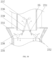
- FIG. 10 is a front view of an interior of the material unloading cylinder of the apparatus for effectively pretreating and recycling the waste battery according to the present invention.
- FIG. 11 is a schematic structural diagram of a knocking rod of the apparatus for effectively pretreating and recycling the waste battery according to the present invention.
- an apparatus for efficiently pretreating and recycling a waste battery comprises a bottom plate 1 , a recycling device 2 , a conveying device 3 and a treatment device 4 .
- One end of a top portion of the bottom plate 1 is fixedly mounted with a bottom portion of the conveying device 3
- the other end of the top portion of the bottom plate 1 is fixedly mounted with a bottom portion of the treatment device 4 .
- the conveying device 3 comprises a controller 31 , a turntable 32 and a supporting frame 36 .
- Atop portion of the turntable 32 is movably mounted with a bottom portion of the controller 31 , and a plurality of fixing assemblies 34 are uniformly provided at a bottom portion of the turntable 32 .
- the fixing assembly 34 comprises a mounting block 341 , a movable rod 343 , a slider 344 , a vacuum negative pressure pump 345 and a sucker 346 .
- Two ends of a bottom portion of the mounting block 341 are symmetrically and fixedly connected with two extension rods 342
- two ends of the movable rod 343 are fixedly mounted with bottom portions of the extension rods 342
- an outer wall of the movable rod 343 is slidably connected with an inner wall of the slider 344 .
- One end of the movable rod 343 is fixedly connected with a driving assembly 348 , the driving assembly 348 drives the slider 344 to reciprocate on the movable rod 343 through an electric push rod 347 , and then the slider 344 drives a battery 35 at a bottom portion to sway left and right.
- the electric push rod 347 is arranged inside the movable rod 343 , one end of the electric push rod 347 is movably mounted with one end of the driving assembly 348 , and the other end of the electric push rod 347 is movably mounted with one end of the slider 344 .
- a top portion of the vacuum negative pressure pump 345 is fixedly mounted with a bottom portion of the slider 344 , the vacuum negative pressure pump 345 may adsorb the battery 35 at the bottom portion by a negative pressure produced by the sucker 346 , and a bottom portion of the vacuum negative pressure pump 345 is movably connected with a top portion of the sucker 346 .
- the treatment device 4 comprises a base 41 , a material conveying pipe 43 , a centrifuge 45 , a material guiding pipe 47 and a recycling treatment cylinder 44 .
- the recycling treatment cylinder 44 comprises a housing 447 , a top cover 441 , a connecting rod 443 , a crushing plate 444 , an acid leaching cylinder 446 , a rotating motor 4412 and a stop block 449 .
- An inner side of a top end of the housing 447 is fixedly connected with a fixing ring 4410
- an inner wall of the fixing ring 4410 is slidably connected with an outer wall of a calcination turntable 442
- a slot 4411 is formed to penetrate through one end of a top portion of the calcination turntable 442
- a top portion of the fixing ring 4410 is fixedly mounted with a bottom portion of the stop block 449
- the top portion of the calcination turntable 442 is fixedly connected with a bottom portion of the connecting rod 443 .
- a positive electrode material solid phase drops on the top portion of the calcination turntable 442 first, the stop block 449 exerts a blocking effect to avoid the positive electrode material solid phase on the calcination turntable 442 from dropping downwardly, and a high temperature calcination assembly is arranged in the stop block 449 .
- the positive electrode material solid phase is subjected to high temperature calcination at the top portion of the calcination turntable 442 at high temperature, the connecting rod 443 is rotated after treatment, the connecting rod 443 drives the calcination turntable 442 to rotate, and the slot 4411 of the calcination turntable 442 is rotated outwardly, so that the treated positive electrode material solid phase drops downwardly on a top portion of the crushing plate 444 .
- the top portion of the crushing plate 444 is movably connected with a bottom portion of the rotating motor 4412 , and a plurality of crushing blades 445 are uniformly arranged outside a bottom end of the rotating motor 4412 .
- the rotating motor 4412 drives the crushing blade 445 at the bottom portion to rotate at a high speed, and the crushing blade 445 may crush the positive electrode material solid phase on the top portion of the crushing plate 444 into powder.
- an inner wall of the housing 447 is fixedly mounted with an outer wall of the crushing plate 444
- an inner wall of a bottom portion of the housing 447 is fixedly connected with a bottom portion of the acid leaching cylinder 446
- a leading-out pipe 448 is provided at one side of the acid leaching cylinder 446 .
- the crushing blade 445 may crush the positive electrode material solid phase on the top portion of the crushing plate 444 into powder, and the powder of the positive electrode material solid phase goes downwardly to the acid leaching cylinder 446 for acid leaching and recycling.
- a top portion of the housing 447 is fixedly mounted with a bottom portion of the top cover 441 , and a bottom portion of the housing 447 is fixedly mounted with one end of the top portion of the bottom plate 1 .
- the top cover 441 is used for ensuring a sealing performance in the housing 447 .
- a bottom portion of the sucker 346 is provided with the battery 35
- a top portion of the base 41 is fixedly mounted with a bottom portion of the centrifuge 45
- a top portion of the centrifuge 45 is provided with a centrifugal motor 46 .
- the centrifugal motor 46 centrifugally filters and separates a slurry in the centrifuge 45 into the positive electrode material solid phase and an N-Methyl Pyrrolidone (NMP) liquid phase, and the N-Methyl Pyrrolidone (NMP) liquid phase is recycled through a separation pipe 42 on a front side, thus recycling the N-Methyl Pyrrolidone (NMP) liquid phase.
- NMP N-Methyl Pyrrolidone
- the front side of the centrifuge 45 is fixedly communicated with the separation pipe 42 , one end of a top portion the centrifuge 45 is fixedly communicated with one end of the material guiding pipe 47 , and one side of the centrifuge 45 is fixedly communicated with one end of the material conveying pipe 43 .
- the material guiding pipe 47 is used for conveying the slurry and the electrolyte in a material unloading cylinder 23 into the centrifuge 45
- the material conveying pipe 43 is used for conveying the positive electrode material solid phase in the centrifuge into the housing 447 .
- one end of the material conveying pipe 43 is fixedly connected with a top portion of the top cover 441 , a top portion of the mounting block 341 is fixedly connected with the bottom portion of the turntable 32 , a top portion of the supporting frame 36 is fixedly connected with the bottom portion of the controller 31 , and a bottom portion of the supporting frame 36 is fixedly mounted with the top portion of the bottom plate 1 .
- the supporting frame 36 exerts supporting and fixing effects, and the controller 31 may drive the turntable 32 to rotate and stop regularly.
- the top portion of the turntable 32 is provided with a plurality of connecting lines 33
- the recycling device 2 comprises a fixing plate 21 , a suction pump 22 , the material unloading cylinder 23 and a bearing ring 27 , an outer wall of the material unloading cylinder 23 is fixedly mounted with an inner side of the bearing ring 27 , and a bottom portion of the material unloading cylinder 23 is provided with a through hole 24 .
- the suction pump 22 may suck the slurry in the battery 35 downwardly through the through hole 24 for dropping, so that the slurry rapidly drops downwardly into the material unloading cylinder 23 , and the recycling device 2 may rapidly convey the slurry in the battery 35 to the treatment device 4 for treatment, thereby improving a recovery efficiency of the slurry in the battery 35 .
- a top portion of the fixing plate 21 is fixedly mounted with a bottom portion of the suction pump 22 , a top portion of the suction pump 22 is movably connected with the bottom portion of the material unloading cylinder 23 , and one side of a bottom end of the material unloading cylinder 23 is fixedly communicated with a material discharging pipe 26 .
- the fixing assembly 34 can not only facilitate fixing and disassembly of the battery 35 , but also make the slurry and the electrolyte in the battery 35 sway to drop rapidly.
- one end of the material discharging pipe 26 is fixedly communicated with one end of the material guiding pipe 47 , a bottom portion of the bearing ring 27 is uniformly and fixedly connected with four supporting rods 25 , and a bottom portion of the supporting rod 25 is fixedly mounted with the top portion of the fixing plate 21 .
- the bearing ring 27 and the supporting rod 25 exert supporting and fixing effects.
- the material unloading cylinder 23 comprises a cylinder body 235 , a knocking rod 236 , a circular ring 233 and a striking ball 237 .
- a top portion of the cylinder body 235 is fixedly mounted with a bottom portion of the circular ring 233 , an inner side of a top end of the cylinder body 235 is symmetrically and fixedly connected with two second bearing rods 232 , an outer wall of the second bearing rod 232 is rotatably connected with a rolling ball 234 , an outer wall of the rolling ball 234 is uniformly and fixedly connected with three supporting rods 238 , an inner side of the cylinder body 235 is symmetrically and fixedly connected with two first bearing rods 231 , an outer wall of the first bearing rod 231 is movably connected with a rotating block 239 , an inner side of the rotating block 239 is fixedly mounted with a bottom end of the knocking rod 236 , a top portion of the knocking rod 2
- One of the supporting rods 238 touches the bottom end of the knocking rod 236 and presses the bottom end of the knocking rod 236 downwardly, the knocking rod 236 and the rotating block 239 are rotated under an action of the supporting rod 238 , and the striking ball 237 at the top end of the knocking rod 236 strikes an inner side of the battery at the moment.
- There is a magnetic attraction force between two second magnetic blocks 241 at the top ends of two knocking rods 236 and there is a magnetic repulsion force between two first magnetic blocks 240 at the bottom ends at the same time.
- the knocking rods 236 on two sides are rotated back to original positions in opposite directions under actions of the magnetic attraction force and the magnetic repulsion force, and when the next supporting rod 238 touches the knocking rod 236 again, the above steps are repeated, so that the striking ball 237 continuously strikes the inner side of the battery 35 to make the battery 35 sway, which may make the slurry and the electrolyte in the battery drop rapidly, thereby improving a recycling efficiency of the slurry and the electrolyte in the battery 35 , and avoiding decomposition gas and volatile toxic gas produced by the electrolyte from rapidly volatilizing outwardly.
- the turntable 32 when the device is in use, the turntable 32 is turned on by the controller 31 first, and the controller 31 may drive the turntable 32 to rotate and stop regularly.
- the fixing assembly 34 , the recycling device 2 and the treatment device 4 are turned on at the same time, the bottom portion of the turntable 32 is provided with the plurality of fixing assemblies 34 , the bottom portion of each fixing assembly 34 is provided with one battery 35 , and the vacuum negative pressure pump 345 at the bottom portion of the fixing assembly 34 may produce a negative pressure through the sucker 346 to absorb the battery 35 at the bottom portion.
- the suction pump 22 sucks the slurry and the electrolyte in the battery 35 downwardly for dropping, the interior of the material unloading cylinder 23 and the interior of the battery 35 are subjected to the downward acting force at the moment, and the supporting rod 238 on the outer wall of the rolling ball 234 is rotated to the axis of the cylinder body 235 under the action of the downward suction force at the moment, so that the rolling balls 234 on two sides are rotated to the inner side of the cylinder body 235 at the same time.
- One of the supporting rods 238 touches the bottom end of the knocking rod 236 and presses the bottom end of the knocking rod 236 downwardly, the knocking rod 236 and the rotating block 239 are rotated under the action of the supporting rod 238 , and the striking ball 237 at the top end of the knocking rod 236 strikes the inner side of the battery 35 at the moment.
- There is the magnetic attraction force between two second magnetic blocks 241 at the top ends of two knocking rods 236 and there is the magnetic repulsion force between two first magnetic blocks 240 at the bottom ends at the same time.
- the knocking rods 236 on two sides are rotated back to the original positions in opposite directions under the actions of the magnetic attraction force and the magnetic repulsion force, and when the next supporting rod 238 touches the knocking rod 236 again, the above steps are repeated, so that the striking ball 237 continuously strikes the inner side of the battery 35 to make the battery 35 sway.
- the driving assembly 348 at the top portion drives the slider 344 to reciprocate rapidly on the movable rod 343 through the electric push rod 347 , and then the slider 344 drives the battery at the bottom portion to sway left and right.
- the fixing assembly 34 can not only facilitate fixing and disassembly of the battery 35 , but also make the slurry and the electrolyte in the battery 35 sway to drop rapidly. Meanwhile, the combination of the material unloading cylinder 23 and the suction pump 22 may rapidly convey the slurry and the electrolyte in the battery 35 to the treatment device 4 for treatment, thereby improving the recycling efficiency of the slurry and the electrolyte in the battery 35 , avoiding the decomposition gas and the volatile toxic gas produced by the electrolyte from rapidly volatilizing outwardly, and solving the problem that harmful gases volatilized from the electrolyte will cause environment pollution.
- the slurry and the electrolyte in the battery 35 completely drop into the material unloading cylinder 23 , and then the turntable 32 is rotated continuously.
- the slurry in the next battery 35 also drops into the material unloading cylinder 23 , then the slurry and the electrolyte in the material unloading cylinder 23 reach the centrifuge 45 through the material discharging pipe 26 and the material guiding pipe 47 , and the centrifugal motor 46 centrifugally filters and separates the slurry in the centrifuge 45 into the positive electrode material solid phase and the N-Methyl Pyrrolidone (NMP) liquid phase.
- NMP N-Methyl Pyrrolidone
- the N-Methyl Pyrrolidone (NMP) liquid phase is recycled through the separation pipe 42 on the front side, thus recycling the N-Methyl Pyrrolidone (NMP) liquid phase.
- the electrolyte is recycled through the separation pipe 42 , the recycled electrolyte is condensed in a sealed state and adsorbed by activated carbon, the decomposition gas produced by the electrolyte is purified, and harmful gases of phosphorus pentafluoride and hydrogen fluoride in the decomposition gas can be eliminated, thereby avoiding environment pollution, and solving the problem of leakage of the harmful gases in a recycling process of the electrolyte of the waste battery in the existing technology.
- the positive electrode material solid phase reaches the treatment device 4 through the material conveying pipe 43 for treatment, the positive electrode material solid phase drops on the top portion of the calcination turntable 442 first, and the stop block 449 exerts a blocking effect to avoid the positive electrode material solid phase on the calcination turntable 442 from dropping downwardly, and the high temperature calcination assembly is arranged in the stop block 449 .
- the positive electrode material solid phase is subjected to high temperature calcination at the top portion of the calcination turntable 442 , the connecting rod 443 is rotated after treatment, the connecting rod 443 drives the calcination turntable 442 to rotate, and the slot 4411 of the calcination turntable 442 is rotated outwardly, so that the treated positive electrode material solid phase drops downwardly on the top portion of the crushing plate 444 .
- the rotating motor 4412 drives the crushing blade 445 at the bottom portion to rotate at a high speed, the crushing blade 445 may crush the positive electrode material solid phase on the top portion of the crushing plate 444 into powder, and the powder of the positive electrode material solid phase goes downwardly to the acid leaching cylinder 446 for acid leaching and recycling, thereby recycling various metal elements in a positive electrode slurry material.
- the treatment mode increases a recycling rate of the metal elements in the positive electrode material, and then improves the efficiency in an operation process, thereby reaching a highest recycling rate of resources, having a simple operation flow, and realizing a high operating efficiency.
Landscapes
- Engineering & Computer Science (AREA)
- Chemical & Material Sciences (AREA)
- Manufacturing & Machinery (AREA)
- General Chemical & Material Sciences (AREA)
- Electrochemistry (AREA)
- Chemical Kinetics & Catalysis (AREA)
- Environmental & Geological Engineering (AREA)
- Life Sciences & Earth Sciences (AREA)
- Mechanical Engineering (AREA)
- Food Science & Technology (AREA)
- Physics & Mathematics (AREA)
- Sustainable Development (AREA)
- Organic Chemistry (AREA)
- Fluid Mechanics (AREA)
- Metallurgy (AREA)
- Materials Engineering (AREA)
- Geology (AREA)
- Geochemistry & Mineralogy (AREA)
- General Life Sciences & Earth Sciences (AREA)
- Thermal Sciences (AREA)
- Processing Of Solid Wastes (AREA)
- Secondary Cells (AREA)
- Manufacture And Refinement Of Metals (AREA)
Applications Claiming Priority (3)
| Application Number | Priority Date | Filing Date | Title |
|---|---|---|---|
| CN202210857686.0A CN115415283B (zh) | 2022-07-21 | 2022-07-21 | 一种废旧电池的高效预处理回收设备 |
| CN202210857686.0 | 2022-07-21 | ||
| PCT/CN2022/120642 WO2024016468A1 (fr) | 2022-07-21 | 2022-09-22 | Équipement de prétraitement et de recyclage efficace pour batteries usagées |
Publications (2)
| Publication Number | Publication Date |
|---|---|
| US20250079542A1 US20250079542A1 (en) | 2025-03-06 |
| US12308403B2 true US12308403B2 (en) | 2025-05-20 |
Family
ID=90054471
Family Applications (1)
| Application Number | Title | Priority Date | Filing Date |
|---|---|---|---|
| US18/284,736 Active US12308403B2 (en) | 2022-07-21 | 2022-09-22 | Apparatus for efficiently pretreating and recycling waste battery |
Country Status (6)
| Country | Link |
|---|---|
| US (1) | US12308403B2 (fr) |
| DE (1) | DE112022000880T5 (fr) |
| ES (1) | ES2976336B2 (fr) |
| GB (1) | GB2624499B (fr) |
| HU (1) | HUP2300329A1 (fr) |
| MA (1) | MA63896B1 (fr) |
Cited By (1)
| Publication number | Priority date | Publication date | Assignee | Title |
|---|---|---|---|---|
| US20240250352A1 (en) * | 2021-06-25 | 2024-07-25 | Guangdong Brunp Recycling Technology Co., Ltd. | Dustproof safety feeding device for power battery black powder acid leaching and feeding |
Families Citing this family (5)
| Publication number | Priority date | Publication date | Assignee | Title |
|---|---|---|---|---|
| US12599915B2 (en) | 2023-08-17 | 2026-04-14 | Mag Ia, Inc. | Automatic magnetic impurity sample isolation |
| US12480840B1 (en) | 2024-08-15 | 2025-11-25 | Mag Ia, Inc. | Automatic high precision battery material assessment system |
| CN120362231B (zh) * | 2025-06-24 | 2025-09-16 | 赣州浩翊科技有限公司 | 一种基于离心力的报废锂电池电解液全封闭收集设备 |
| CN120749272B (zh) * | 2025-09-05 | 2026-02-17 | 赣州龙凯科技有限公司 | 一种废弃锂电池卷芯废料分离设备 |
| CN120901055B (zh) * | 2025-10-09 | 2026-01-30 | 烟台开发区博森科技发展有限公司 | 一种全自动金属切屑压块装置 |
Citations (18)
| Publication number | Priority date | Publication date | Assignee | Title |
|---|---|---|---|---|
| CN101183740A (zh) | 2007-12-24 | 2008-05-21 | 深圳市格林美高新技术股份有限公司 | 一种废弃电池的控制破碎回收方法及其系统 |
| CN101212074A (zh) | 2006-12-30 | 2008-07-02 | 上海比亚迪有限公司 | 一种锂离子电池正极材料的回收方法 |
| US7833646B2 (en) * | 2002-02-01 | 2010-11-16 | Batrec Industrie Ag | Method of and apparatus for dismantling and storage of objects comprising alkali metals, such as alkali metal containing batteries |
| CN102029283A (zh) | 2010-02-05 | 2011-04-27 | 伟翔环保科技发展(上海)有限公司 | 锂电池组成材料的资源化分离系统 |
| CN102208707A (zh) | 2011-05-12 | 2011-10-05 | 合肥工业大学 | 一种废旧磷酸铁锂电池正极材料修复再生的方法 |
| JP2014055312A (ja) | 2012-09-11 | 2014-03-27 | Hitachi Ltd | リチウムイオン電池の再資源化方法、およびその装置 |
| US20170077564A1 (en) | 2012-04-04 | 2017-03-16 | Worcester Polytechnic Institute | Method and apparatus for recycling lithium-ion batteries |
| CN207371677U (zh) | 2017-09-20 | 2018-05-18 | 广州市滨一塑料机械设备有限公司 | 一种废旧锂电池回收撕碎处理设备 |
| CN209329087U (zh) | 2018-12-12 | 2019-08-30 | 连云港德立信电子科技有限公司 | 锂电池回收装置 |
| CN110788120A (zh) * | 2019-11-15 | 2020-02-14 | 湖南金凯循环科技有限公司 | 一种废旧锂电池用设备 |
| CN111036651A (zh) | 2019-12-26 | 2020-04-21 | 甘肃睿思科新材料有限公司 | 一种锂电池正极废弃浆料的回收系统 |
| CN111841832A (zh) | 2020-07-03 | 2020-10-30 | 安徽南都华铂新材料科技有限公司 | 一种锂电池回收用破碎设备及其使用方法 |
| CN112670609A (zh) | 2020-10-09 | 2021-04-16 | 武汉瑞科美新能源有限责任公司 | 废旧锂电池石墨负极全组分一体化回收与再生方法和装置 |
| US20210203017A1 (en) | 2019-12-31 | 2021-07-01 | Omega Harvested Metallurgical, Inc | Coke powder as a discharging agent for waste battery recycling and method thereof |
| CN113458119A (zh) * | 2021-07-05 | 2021-10-01 | 太和县大华能源科技有限公司 | 一种铅酸电池环保回收装置及其使用方法 |
| CN113648670A (zh) | 2021-07-15 | 2021-11-16 | 广东邦普循环科技有限公司 | 锂电池浆料的回收方法及用于回收其的设备 |
| US11450902B2 (en) * | 2017-12-11 | 2022-09-20 | Institute Of Process Engineering, Chinese Academy Of Sciences | Battery pre-processing apparatus and method |
| US12119463B2 (en) * | 2016-10-20 | 2024-10-15 | Duesenfeld Gmbh | Recycling method for treating used batteries, in particular rechargeable batteries, and battery processing installation |
Family Cites Families (4)
| Publication number | Priority date | Publication date | Assignee | Title |
|---|---|---|---|---|
| CN105826629B (zh) * | 2016-05-13 | 2018-05-25 | 国网河南省电力公司电力科学研究院 | 一种废旧锂电池全组分物料分离收集装置及方法 |
| CN109553011A (zh) * | 2019-01-17 | 2019-04-02 | 长江南京航道工程局 | 一种吸盘式联锁块起吊搬运装置 |
| CN111872021B (zh) * | 2020-07-08 | 2022-09-27 | 山东电亮亮信息科技有限公司 | 一种环保型废锂电池回收处理系统 |
| CN112045895A (zh) * | 2020-08-21 | 2020-12-08 | 高琦 | 一种基于轮胎加工的胶料回收用切片系统 |
-
2022
- 2022-09-22 ES ES202390142A patent/ES2976336B2/es active Active
- 2022-09-22 MA MA63896A patent/MA63896B1/fr unknown
- 2022-09-22 HU HU2300329A patent/HUP2300329A1/hu unknown
- 2022-09-22 DE DE112022000880.6T patent/DE112022000880T5/de active Pending
- 2022-09-22 GB GB2313089.1A patent/GB2624499B/en active Active
- 2022-09-22 US US18/284,736 patent/US12308403B2/en active Active
Patent Citations (19)
| Publication number | Priority date | Publication date | Assignee | Title |
|---|---|---|---|---|
| US7833646B2 (en) * | 2002-02-01 | 2010-11-16 | Batrec Industrie Ag | Method of and apparatus for dismantling and storage of objects comprising alkali metals, such as alkali metal containing batteries |
| CN101212074A (zh) | 2006-12-30 | 2008-07-02 | 上海比亚迪有限公司 | 一种锂离子电池正极材料的回收方法 |
| CN101183740A (zh) | 2007-12-24 | 2008-05-21 | 深圳市格林美高新技术股份有限公司 | 一种废弃电池的控制破碎回收方法及其系统 |
| CN102029283A (zh) | 2010-02-05 | 2011-04-27 | 伟翔环保科技发展(上海)有限公司 | 锂电池组成材料的资源化分离系统 |
| CN102208707A (zh) | 2011-05-12 | 2011-10-05 | 合肥工业大学 | 一种废旧磷酸铁锂电池正极材料修复再生的方法 |
| US20170077564A1 (en) | 2012-04-04 | 2017-03-16 | Worcester Polytechnic Institute | Method and apparatus for recycling lithium-ion batteries |
| JP2014055312A (ja) | 2012-09-11 | 2014-03-27 | Hitachi Ltd | リチウムイオン電池の再資源化方法、およびその装置 |
| US12119463B2 (en) * | 2016-10-20 | 2024-10-15 | Duesenfeld Gmbh | Recycling method for treating used batteries, in particular rechargeable batteries, and battery processing installation |
| CN207371677U (zh) | 2017-09-20 | 2018-05-18 | 广州市滨一塑料机械设备有限公司 | 一种废旧锂电池回收撕碎处理设备 |
| US11450902B2 (en) * | 2017-12-11 | 2022-09-20 | Institute Of Process Engineering, Chinese Academy Of Sciences | Battery pre-processing apparatus and method |
| CN209329087U (zh) | 2018-12-12 | 2019-08-30 | 连云港德立信电子科技有限公司 | 锂电池回收装置 |
| CN110788120A (zh) * | 2019-11-15 | 2020-02-14 | 湖南金凯循环科技有限公司 | 一种废旧锂电池用设备 |
| CN111036651A (zh) | 2019-12-26 | 2020-04-21 | 甘肃睿思科新材料有限公司 | 一种锂电池正极废弃浆料的回收系统 |
| US20210203017A1 (en) | 2019-12-31 | 2021-07-01 | Omega Harvested Metallurgical, Inc | Coke powder as a discharging agent for waste battery recycling and method thereof |
| CN111841832A (zh) | 2020-07-03 | 2020-10-30 | 安徽南都华铂新材料科技有限公司 | 一种锂电池回收用破碎设备及其使用方法 |
| CN112670609A (zh) | 2020-10-09 | 2021-04-16 | 武汉瑞科美新能源有限责任公司 | 废旧锂电池石墨负极全组分一体化回收与再生方法和装置 |
| CN113458119A (zh) * | 2021-07-05 | 2021-10-01 | 太和县大华能源科技有限公司 | 一种铅酸电池环保回收装置及其使用方法 |
| CN113648670A (zh) | 2021-07-15 | 2021-11-16 | 广东邦普循环科技有限公司 | 锂电池浆料的回收方法及用于回收其的设备 |
| US11894531B2 (en) * | 2021-07-15 | 2024-02-06 | Guangdong Brunp Recycling Technology Co., Ltd. | Method for recovering lithium battery slurry and device for recovery of same |
Non-Patent Citations (6)
| Title |
|---|
| China Search Report, Chinese Patent Application No. 202210857686.0, dated, Mar. 14, 2023, 4 pages. |
| CN110788120, Yan et al., A device For Waste Lithium Battery, Feb. 14, 2020 (Year: 2020). * |
| CN113458119, Han et al. , Lead-Acid Battery Environment-Friendly Recycling Device and Using Method, Oct. 1, 2021 (Year: 2021). * |
| Notification to Grant in CN Application No. 202210857686.0, mailed Mar. 19, 2023, an English Translation attached herewith (3 pages). |
| PCT Search Report, PCT Application No. PCT/CN2022/120642, dated Dec. 26, 2022, 6 pages. |
| PCT Written Opinion, PCT Application No. PCT/CN2022/120642, dated Dec. 26, 2022, 5 pages. |
Cited By (2)
| Publication number | Priority date | Publication date | Assignee | Title |
|---|---|---|---|---|
| US20240250352A1 (en) * | 2021-06-25 | 2024-07-25 | Guangdong Brunp Recycling Technology Co., Ltd. | Dustproof safety feeding device for power battery black powder acid leaching and feeding |
| US12374741B2 (en) * | 2021-06-25 | 2025-07-29 | Guangdong Brunp Recycling Technology Co., Ltd. | Dustproof safety feeding device for power battery black powder acid leaching and feeding |
Also Published As
| Publication number | Publication date |
|---|---|
| DE112022000880T5 (de) | 2024-03-14 |
| ES2976336A2 (es) | 2024-07-30 |
| MA63896B1 (fr) | 2025-08-29 |
| ES2976336R1 (es) | 2024-09-23 |
| ES2976336B2 (es) | 2025-10-06 |
| GB2624499B (en) | 2025-04-09 |
| MA63896A1 (fr) | 2025-05-30 |
| GB202313089D0 (en) | 2023-10-11 |
| US20250079542A1 (en) | 2025-03-06 |
| GB2624499A (en) | 2024-05-22 |
| HUP2300329A1 (hu) | 2024-07-28 |
Similar Documents
| Publication | Publication Date | Title |
|---|---|---|
| US12308403B2 (en) | Apparatus for efficiently pretreating and recycling waste battery | |
| WO2024016468A1 (fr) | Équipement de prétraitement et de recyclage efficace pour batteries usagées | |
| CN113976595B (zh) | 一种软包锂离子电池回收处理系统及工艺 | |
| CN109193064B (zh) | 一种废旧动力锂电池有价成分分选回收的方法 | |
| CN111530884B (zh) | 一种动力锂电池单体回收方法 | |
| CN105826629B (zh) | 一种废旧锂电池全组分物料分离收集装置及方法 | |
| KR102695192B1 (ko) | 리튬이차전지용 양극활물질 연속 회수 장치 및 이를 이용한 회수 방법 | |
| CN110581323A (zh) | 一种废旧磷酸铁锂电池正极材料的原位再生方法 | |
| AU2021103810A4 (en) | Device and method for integrated recycling and regeneration of full components of graphite anode of waste lithium battery | |
| CN108281729A (zh) | 一种废旧锂离子电池电解液回收工艺 | |
| CN205609702U (zh) | 一种废旧锂电池全组分物料分离收集装置 | |
| CN108321453B (zh) | 一种废旧锂电池回收系统设备 | |
| CN114899522B (zh) | 一种废旧三元软包锂电池的处理方法 | |
| CN104600392A (zh) | 一种废旧锂离子电池电解液回收方法 | |
| CN111430832A (zh) | 一种废旧三元锂离子电池无需放电预处理的全资源回收方法 | |
| CN111525209B (zh) | 一种动力锂电池的回收方法 | |
| CN109888370A (zh) | 废旧锂离子电池热解方法及系统 | |
| CN108565521A (zh) | 一种直接回收利用石墨负极材料的方法 | |
| CN115007614A (zh) | 一种废弃锂离子电池正负极片破碎料分选方法 | |
| KR20230122835A (ko) | 이차전지 폐슬러지 재활용 공정 | |
| CN114749463A (zh) | 一种三元电池材料中镍钴元素的快速回收装置及回收方法 | |
| CN120221836A (zh) | 一种高效电解液回收与磷酸铁锂正极材料再生装置 | |
| CN209526167U (zh) | 废旧锂离子电池热解系统 | |
| CN211957836U (zh) | 一种无污染锂电池分解处理系统 | |
| CN211125915U (zh) | 一种处理废旧电池电解液的装置 |
Legal Events
| Date | Code | Title | Description |
|---|---|---|---|
| AS | Assignment |
Owner name: HUNAN BRUNP RECYCLING TECHNOLOGY CO., LTD., CHINA Free format text: ASSIGNMENT OF ASSIGNORS INTEREST;ASSIGNORS:XIE, YINGHAO;LI, AIXIA;ZHANG, XUEMEI;AND OTHERS;REEL/FRAME:065082/0291 Effective date: 20230922 Owner name: GUANGDONG BRUNP RECYCLING TECHNOLOGY CO., LTD., CHINA Free format text: ASSIGNMENT OF ASSIGNORS INTEREST;ASSIGNORS:XIE, YINGHAO;LI, AIXIA;ZHANG, XUEMEI;AND OTHERS;REEL/FRAME:065082/0291 Effective date: 20230922 |
|
| FEPP | Fee payment procedure |
Free format text: ENTITY STATUS SET TO UNDISCOUNTED (ORIGINAL EVENT CODE: BIG.); ENTITY STATUS OF PATENT OWNER: LARGE ENTITY |
|
| STPP | Information on status: patent application and granting procedure in general |
Free format text: NON FINAL ACTION MAILED |
|
| STCF | Information on status: patent grant |
Free format text: PATENTED CASE |