US12347666B2 - Positioning of a needle-like component in a mass spectrometry system - Google Patents
Positioning of a needle-like component in a mass spectrometry system Download PDFInfo
- Publication number
- US12347666B2 US12347666B2 US17/453,189 US202117453189A US12347666B2 US 12347666 B2 US12347666 B2 US 12347666B2 US 202117453189 A US202117453189 A US 202117453189A US 12347666 B2 US12347666 B2 US 12347666B2
- Authority
- US
- United States
- Prior art keywords
- needle
- component
- packaging
- receptacle
- actuator
- Prior art date
- Legal status (The legal status is an assumption and is not a legal conclusion. Google has not performed a legal analysis and makes no representation as to the accuracy of the status listed.)
- Active, expires
Links
Images



Classifications
-
- G—PHYSICS
- G01—MEASURING; TESTING
- G01N—INVESTIGATING OR ANALYSING MATERIALS BY DETERMINING THEIR CHEMICAL OR PHYSICAL PROPERTIES
- G01N30/00—Investigating or analysing materials by separation into components using adsorption, absorption or similar phenomena or using ion-exchange, e.g. chromatography or field flow fractionation
- G01N30/02—Column chromatography
-
- H—ELECTRICITY
- H01—ELECTRIC ELEMENTS
- H01J—ELECTRIC DISCHARGE TUBES OR DISCHARGE LAMPS
- H01J49/00—Particle spectrometers or separator tubes
- H01J49/02—Details
- H01J49/06—Electron- or ion-optical arrangements
- H01J49/068—Mounting, supporting, spacing, or insulating electrodes
-
- H—ELECTRICITY
- H01—ELECTRIC ELEMENTS
- H01J—ELECTRIC DISCHARGE TUBES OR DISCHARGE LAMPS
- H01J49/00—Particle spectrometers or separator tubes
- H01J49/02—Details
- H01J49/10—Ion sources; Ion guns
- H01J49/16—Ion sources; Ion guns using surface ionisation, e.g. field-, thermionic- or photo-emission
- H01J49/165—Electrospray ionisation
- H01J49/167—Capillaries and nozzles specially adapted therefor
-
- G—PHYSICS
- G01—MEASURING; TESTING
- G01N—INVESTIGATING OR ANALYSING MATERIALS BY DETERMINING THEIR CHEMICAL OR PHYSICAL PROPERTIES
- G01N27/00—Investigating or analysing materials by the use of electric, electrochemical, or magnetic means
- G01N27/62—Investigating or analysing materials by the use of electric, electrochemical, or magnetic means by investigating the ionisation of gases, e.g. aerosols; by investigating electric discharges, e.g. emission of cathode
-
- G—PHYSICS
- G01—MEASURING; TESTING
- G01N—INVESTIGATING OR ANALYSING MATERIALS BY DETERMINING THEIR CHEMICAL OR PHYSICAL PROPERTIES
- G01N27/00—Investigating or analysing materials by the use of electric, electrochemical, or magnetic means
- G01N27/62—Investigating or analysing materials by the use of electric, electrochemical, or magnetic means by investigating the ionisation of gases, e.g. aerosols; by investigating electric discharges, e.g. emission of cathode
- G01N27/626—Investigating or analysing materials by the use of electric, electrochemical, or magnetic means by investigating the ionisation of gases, e.g. aerosols; by investigating electric discharges, e.g. emission of cathode using heat to ionise a gas
-
- G—PHYSICS
- G01—MEASURING; TESTING
- G01N—INVESTIGATING OR ANALYSING MATERIALS BY DETERMINING THEIR CHEMICAL OR PHYSICAL PROPERTIES
- G01N30/00—Investigating or analysing materials by separation into components using adsorption, absorption or similar phenomena or using ion-exchange, e.g. chromatography or field flow fractionation
- G01N30/02—Column chromatography
- G01N30/62—Detectors specially adapted therefor
- G01N30/72—Mass spectrometers
-
- G—PHYSICS
- G01—MEASURING; TESTING
- G01N—INVESTIGATING OR ANALYSING MATERIALS BY DETERMINING THEIR CHEMICAL OR PHYSICAL PROPERTIES
- G01N30/00—Investigating or analysing materials by separation into components using adsorption, absorption or similar phenomena or using ion-exchange, e.g. chromatography or field flow fractionation
- G01N30/02—Column chromatography
- G01N30/62—Detectors specially adapted therefor
- G01N30/72—Mass spectrometers
- G01N30/7233—Mass spectrometers interfaced to liquid or supercritical fluid chromatograph
- G01N30/724—Nebulising, aerosol formation or ionisation
- G01N30/7266—Nebulising, aerosol formation or ionisation by electric field, e.g. electrospray
-
- H—ELECTRICITY
- H01—ELECTRIC ELEMENTS
- H01J—ELECTRIC DISCHARGE TUBES OR DISCHARGE LAMPS
- H01J49/00—Particle spectrometers or separator tubes
- H01J49/0027—Methods for using particle spectrometers
- H01J49/0031—Step by step routines describing the use of the apparatus
-
- H—ELECTRICITY
- H01—ELECTRIC ELEMENTS
- H01J—ELECTRIC DISCHARGE TUBES OR DISCHARGE LAMPS
- H01J49/00—Particle spectrometers or separator tubes
- H01J49/02—Details
- H01J49/04—Arrangements for introducing or extracting samples to be analysed, e.g. vacuum locks; Arrangements for external adjustment of electron- or ion-optical components
- H01J49/0495—Vacuum locks; Valves
-
- G—PHYSICS
- G01—MEASURING; TESTING
- G01N—INVESTIGATING OR ANALYSING MATERIALS BY DETERMINING THEIR CHEMICAL OR PHYSICAL PROPERTIES
- G01N30/00—Investigating or analysing materials by separation into components using adsorption, absorption or similar phenomena or using ion-exchange, e.g. chromatography or field flow fractionation
- G01N30/02—Column chromatography
- G01N2030/022—Column chromatography characterised by the kind of separation mechanism
- G01N2030/027—Liquid chromatography
-
- H—ELECTRICITY
- H01—ELECTRIC ELEMENTS
- H01J—ELECTRIC DISCHARGE TUBES OR DISCHARGE LAMPS
- H01J49/00—Particle spectrometers or separator tubes
- H01J49/02—Details
- H01J49/10—Ion sources; Ion guns
- H01J49/16—Ion sources; Ion guns using surface ionisation, e.g. field-, thermionic- or photo-emission
Definitions
- the process of replacing the needle-like component can include one or more of manually taking the component out of the box and manually inserting the component in the MS system (possibly with the help of a special tool).
- This is not a straightforward task and can require a certain level of skill and training due to the fragile and delicate nature of the needle-like component.
- a correct position of the needle-like component inside the ionization source cannot be obtained in some situations.
- the needle-like component can be bent during the insertion process, which can negatively affect the overall performance of the MS system.
- additional service visits may be required if this sophisticated exchange process of the needle-like component fails.
- a packaging for a needle-like component of a mass spectrometry (MS) system comprising a receptacle configured for storing the needle-like component in a secured position inside the receptacle, and an actuator configured to move the needle-like component from the secured position inside the receptacle to a mounting position in which the needle-like component projects out of the receptacle for mounting the needle-like component to the MS system.
- MS mass spectrometry
- a method for mounting a needle-like component in a mass spectrometry (MS) system comprising obtaining a packaging including the needle-like component in a secured position inside a receptacle of the packaging; and moving the needle-like component by activating an actuator of the packaging from the secured position inside the receptacle to a mounting position in which the needle-like component projects out of the receptacle to mount the needle-like component to the MS system.
- MS mass spectrometry
- a method for removing a needle-like component from a mass spectrometry (MS) system comprising engaging a packaging for the needle-like component with the needle-like component mounted to the MS system by activating an actuator of the packaging; and retracting the needle-like component from the mounting position into a secured position inside a receptacle of the packaging by activating the actuator of the packaging.
- MS mass spectrometry
- the present technique can have the advantage that it does not involve the usage of any special sophisticated installation tools. This can make installing the needle-like components easier (e.g., for personnel having received no or little training in servicing the MS system) and/or less costly.
- the technique of the present disclosure can facilitate safe removal and disposal of an old and potentially contaminated needle-like component.
- the packaging of the present disclosure can minimize a risk of direct contact by a user with a sharp tip of the needle-like component.
- the packing of the present technique can provide safe transport and storage of the needle-like component, which is a delicate part in the ionization source of the MS system.
- the entire process of inserting/replacing the needle-like component using the present packaging might not require any special technical skills on the user side and can therefore potentially be performed by an inexperienced user without the need to call a skilled service technician, as is the case for some prior art MS system.
- FIGS. 1 a and 1 b show schematically a needle-like component of a mass spectrometry (MS) system inside a receptacle of a packaging in accordance with an embodiment of the present disclosure
- FIG. 2 illustrates schematically the MS system including an ionization source with the needle-like component forming a replaceable part of the ionization source and a mass spectrometer coupled to the ionization source in accordance with an embodiment of the present disclosure
- FIG. 3 shows schematically the needle-like component projected out of the receptacle for mounting the needle-like component to the mounting position in the MS system in accordance with an embodiment of the present disclosure
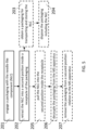
- FIG. 4 is a flow diagram illustrating a packaging method for the needle-like component of the MS system in accordance with an embodiment of the present disclosure
- FIG. 5 is a flow diagram illustrating a method for removing the needle-like component from the MS system in accordance with an embodiment of the present disclosure.
- FIG. 6 shows schematically an MS system comprising a liquid chromatography (LC) system, where the LC system is connected to the electrospray ionization (ESI) source in accordance with an embodiment of the present disclosure.
- LC liquid chromatography
- the liquid is nebulized in a volume downstream of the sprayer capillary where ionization takes place and the charged analyte molecules thereby obtained are brought into a gaseous phase.
- a sampling device e.g., a sampling capillary or orifice
- a mass spectrometry system can include one or more mass spectrometers and/or one or more ionization sources as discussed above.
- the MS system can include one or more LC system or FIS as discussed above.
- FIGS. 1 a , 1 b , 2 and 3 various aspects of the techniques of the present disclosure related to a packaging for a needle-like component in a mass spectrometry (MS) system and to a method for mounting or removing the needle-like component from the MS system will subsequently be summarized in flow charts shown, respectively, in FIGS. 4 and 5 .
- FIGS. 4 and 5 some further aspects of the present disclosure will be given on the example of FIG. 6 , when the MS system comprises a liquid chromatographic (LC) system.
- LC liquid chromatographic
- the packaging can comprise a receptacle 11 configured for storing the needle-like component 10 in a secured position inside the receptacle 11 .
- the receptacle 11 can be sealed to the ambient environment (until the needle-like component is moved to the mounting position).
- the receptacle 11 can include one or more openings but nevertheless shield the needle-like component 10 from the ambient environment.
- the receptacle in an example can include a plastic material (e.g., consist of a plastic material).
- the receptacle can be at least partially transparent (to allow inspecting the inside of the receptacle) or non-transparent.
- the receptacle can include a glass material or other materials.
- the receptacle can include an opening through which the need-like element can be moved to project out of the receptacle.
- the receptacle e.g., the opening
- the receptacle can be closed by a cap 15 (e.g., by a screw cap) to prevent dust or dirt from penetrating and accumulating in the receptacle when the needle-like component is in the secured position inside the receptacle.
- the cap 15 can be configured to repeatedly close the receptacle or can be a single use cap.
- the closing cap can be a screw cap comprising a metallic element.
- a plastic cap without screw or other means known in the art can be used to close the receptacle 11 .
- a removable membrane can be provided to close an opening of the receptacle (e.g., the removable membrane can be removed before actuating the actuator and/or before attaching the packaging to the MS system).
- the actuator e.g., the pushrod or the pushbutton
- the actuator can be coupled to the needle-like element in the receptacle through a detachable coupling mechanism (i.e., the actuator can be detached from the needle-like element once the needle like element is in the mounting position).
- the actuator is configured to engage with the needle-like element through frictional force.
- the mounting method comprises obtaining 101 a packaging including the needle-like component in a secured position inside a receptacle of the packaging.
- the technique includes moving 102 the needle-like component by activating an actuator of the packaging from the secured position inside the receptacle to a mounting position in which the needle-like component projects out of the receptacle for mounting the needle-like component to the MS system.
- the needle-like component is a capillary or an electrode, optionally an electrospray ionization (ESI) capillary or sprayer needle as discussed above in connection with the embodiment shown in FIG. 2 (further examples of needle-like components will be discussed below).
- the packaging of the present techniques can comprise the needle-like component.
- the techniques include using the packaging with the needle-like component to install the latter into the MS system, for example, into the ESI source of FIGS. 2 and 3 , at the stage of initially setting up a new MS system for operation.
- the packaging 1 can further comprise a connector element 13 configured to couple 103 the packaging with the MS system.
- the connector element can be further configured to secure 104 the packaging relative to the MS system.
- the needle-like component can be aligned 105 at a predefined angle with a tube 21 (e.g., a nebulizer tube) of a housing 22 of the needle-like component of the MS system (or in alignment with another component of the MS system).
- the needle-like component can be aligned in parallel with the tube 21 , so that the predefined angle will be substantially zero.
- the needle-like component can be aligned to form a non-zero angle of inclination with the tube 21 (for example, an inclination angle may be between 0° and 1°, between 0° and 2°, or between 0° and 5°).
- securing the packaging relative to the MS system can mean securing the packaging relative to the ionization source of the MS system, e.g., relative to the ESI source as shown in the examples of FIGS. 2 and 3 .
- the housing 22 of the needle-like component of the MS system can be a housing of the needle-like component of the ESI source.
- the connector element 13 of the present techniques can include a fastening element.
- the fastening element can be a thread so that the packaging can be secured to the MS system by screwing the packaging to a corresponding element of the MS system.
- the fastening element can be a pin or a key so that the packaging can be secured to the MS system by connecting the packaging to a corresponding recess of the MS system.
- the packaging can include a recess so that the packaging can be secured to the MS system by connecting a corresponding pin or key of the MS system to the recess.
- the fastening element can be an interlock, a shaped surface or another suitable fastening element to be coupled to a respective counterpart in the MS system to couple the packaging to the MS system.
- the actuator of the present disclosure can be a pusher configured to push the needle-like component from the secured position inside the receptacle into the mounting position in the MS system (see, e.g., FIG. 3 ).
- the pusher can be constructed as a pushbutton 12 a shown in FIG. 1 a .
- the pusher can be designed as a pushrod 12 b depicted in FIG. 1 b .
- the actuator can include any mechanical, electro-mechanical or other means to effect movement of the needle-like component from the secured position to the mounting position.
- the actuator can be configured to be actuated by pulling or rotating a respective component (e.g., a button or a handle) to move the needle-like component from the secured position into the mounting position.
- the packaging can include suitable elements to translate a movement of the respective component (e.g., the button or the handle) into a translatory movement to move the needle-like component from the secured position to mounting position.
- the elements to translate a movement can include a gearing mechanism.
- the gearing mechanism may comprise a gear wheel with discrete step sizes and an optional attached counter that is triggered by the gear wheel.
- the actuator or pusher can be configured to also operate as a puller (e.g., to move the needle-like component back and forth or to remove the needle-like component from the MS system—both examples are discussed in detail below).
- the packaging is configured to facilitate inserting 106 the needle-like component into the MS system, e.g., by pushing the pusher to move the needle-like component to the mounting position in the MS system.
- the pusher can be activated by a user (e.g., manually) to provide pushing the needle-like component from the secured position into the mounting position.
- the orientation of the needle-like component at the predefined angle with the tube 21 of the housing 22 of the needle-like component in the secured position of the packaging relative to the MS system can be the same as in the mounting position.
- moving the needle-like component to the mounting position can be substantially continuous towards the mounting position.
- moving the needle-like component to the mounting position can be performed in a stepwise manner, for instance, moving can be performed in one direction towards the mounting position at different velocities for different points of time, or moving can be performed back and forth in forward and, respectively, backward directions with respect to the mounting position.
- moving the needle-like component to the mounting position can be carried out by rotating the pusher around an axis parallel to the needle-like component or around an axis aligned at the predefined angle defined above (e.g., in a clockwise and/or counterclockwise manner during moving the needle-like component to the mounting position).
- the packaging 1 can comprise a resilient element 14 configured to keep the needle-like component in the secured position inside the receptacle 11 .
- the resilient element can be a spring element 14 as illustrated in the embodiments presented in FIGS. 1 a and 1 b .
- a resilient sleeve, tube or other resilient means can be used as the resilient element for keeping the needle-like component in the secured position inside the receptacle.
- the resilient element can extend between the pusher 12 a , 12 b and end of the receptacle closed by the closing cap 15 or other means for closing an opening of the receptacle (e.g., the resilient means can be supported and/or fastened at the end of the receptacle closed by the closing cap 15 ).
- the resilient element can be shorter than the distance between the pusher and the closing cap (for instance, 5%, 10% or 20% shorter).
- the resilient element 14 can surround the needle-like element in the secured position such that the latter can be positioned inside the resilient element.
- the packaging 1 can comprise an indicator configured to indicate one or more states of the needle-like components (e.g., one or more positions of the needle-like component before and/or during the placement process).
- the indicator can indicate the states in various ways (e.g., by presenting a color, a symbol and/or a textual information or a sound).
- the indicator may indicate a first state when the needle-like component 10 is in the secured position inside the receptacle 11 .
- the indicator can light up in a predetermined color (e.g., red) when the needle-like component 10 is in the secured position inside the receptacle 11 .
- the indicator can be a movable mechanical element that presents a predetermined color (e.g., red) when the needle-like component 10 is in the secured position inside the receptacle.
- a predetermined color e.g., red
- the fact that the needle-like component is in the secured position may be determined, for example, based on a measured force exerted by the resilient element 14 or by a position detection component.
- the packaging 1 can be configured to provide a first resistance against the movement of the actuator 12 a ; 12 b when the actuator is moved to insert the needle-like component 10 into the MS system 100 .
- a user can experience the first resistance when inserting the needle-like component into the MS system (e.g., over 80% or more of a translatory movement from the secured to position to the mounting position). In some examples, this may mean that a velocity at which the needle-like element is inserted by the user into the mounting position in the MS system can be limited or can be reduced by the first resistance (e.g., compared to a situation where the first resistance is not present).
- the first resistance against the movement of the actuator can be provided by a resilient element 14 .
- the resilient element that can provide the first resistance may differ from the resilient element that can keep the needle-like component in the secured position inside the receptacle. In other examples, the same resilient element can provide the first resistance against the movement of the actuator and can keep the needle-like component in the secured position inside the receptacle.
- the resilient element providing the first resistance can be a spring element, a resilient sleeve, tube or other resilient means known in the art.
- the packaging 1 can comprise the indicator mentioned above that may indicate a second state when the needle-like component 10 is inserted into the MS system. For example, the indicator can light up in a predetermined color (e.g., orange) when the needle-like component 10 is inserted into the MS system.
- the movable mechanical element can present a predetermined color (e.g., orange) when the needle-like component 10 is inserted into the MS system.
- a predetermined color e.g., orange
- the fact that the needle-like component is inserted into the MS system may be determined, for example, based on the first resistance provided by the resilient element 14 or by a position detection component.
- the packaging and/or the needle-like component of the present disclosure can be further configured to provide a second resistance against the movement of the actuator when the needle-like component is registered in the mounting position.
- the second resistance can be larger than the first resistance against the movement of the actuator mentioned above.
- the actuator cannot be moved beyond a point when the needle-like component is registered in the mounting position.
- the second resistance can be provided by a blocking element of the packaging.
- the second resistance can be provided by a blocking element of the needle-like component.
- the blocking element can be a ferrule of the needle-like element.
- the blocking element can be a prevention pin or other blocking element of the packaging or the MS system.
- a user when a user reaches the second resistance, she or he can conclude that the needle-like element is well positioned and has reached the mounting position in the MS system.
- the packaging without the needle-like component can be then decoupled from the MS system.
- the user can finally fix the needle-like component in the MS system using mounting means (for example, a mounting nut).
- the packaging 1 of the present disclosure can include a thread configured to allow turning of an outer part of the packaging with respect to an inner part of the packaging.
- the inner part of the packaging can be configured to keep the needle-like component in the secured position inside the receptacle.
- the method for removing a needle-like component comprises engaging 201 a packaging for the needle-like component with the needle-like component mounted to the MS system by activating an actuator of the packaging.
- the techniques of the present disclosure further comprise retracting 202 the needle-like component from the mounting position into a secured position inside a receptacle of the packaging by activating the actuator of the packaging.
- the engaging and retracting steps can be performed with respect to the old needle-like component when it is removed from the MS system.
- the packaging described above may be used for this purpose, which includes the resilient element 14 to keep the needle-like component in the secured position inside the receptacle.
- the packaging can include an additional coupling mechanism.
- the additional coupling mechanism e.g., a pin or thread
- the thread can be configured to provide engaging with the needle-like component being in the mounting position and retracting the needle-like component from the mounting position into the secured position inside the receptacle.
- using the thread and the additional coupling mechanism can facilitate the safe removal of the old capillary from the MS.
- the retracting step of the present disclosure can comprise obtaining 203 a packaging as defined in the present disclosure (e.g., a packaging without an included needle-like component).
- the present techniques can ensure safe storage of the needle-like component (e.g., the old or a new needle-like component) during its transport. Specifically, the engaging and retracting steps of the present techniques can be carried out such that the user may avoid direct contact with a sharp tip of the needle-like component, which can potentially be contaminated with infectious or otherwise dangerous material (if it is removed from the MS system).
- the present techniques can further comprise disposing 204 the packaging including the needle-like component in the secured position inside the receptacle of the packaging. For instance, the packaging can be disposed of together with the old needle-like component retracted into the secured position inside the receptacle.
- the retracting step of the present technique can further include pulling the needle-like component from the mounting position in the MS system into the secured position inside the receptacle.
- pulling the needle-like component can be carried out when the packaging is coupled with the MS system.
- the pulling step can be performed by the same actuator (such as, e.g., a pusher, pushrod, pushbutton, rotary rod, etc., disclosed above) that is used for moving the needle-like component (for example, the new needle-like component) to the mounting position in the MS system.
- the actuator of the present disclosure can comprise additional pushing/pulling means listed above to facilitate pulling the needle-like component from the mounting position in the MS system.
- additional pushing/pulling means may comprise a clamp-like mechanism.
- the retracting step of the present disclosure can include decoupling 206 the packaging from the MS system.
- decoupling the packaging from the MS system can include decoupling the packaging from a respective counterpart in the MS system.
- the respective counterpart in this context may be the counterpart to which the packaging 1 can be coupled by the connector 13 in accordance with the above discussions with respect to the second general aspect, when the packaging is coupled with the MS system.
- decoupling the packaging from the MS system can involve releasing/disconnecting the connector 13 (e.g., thread, pin, interlock, key, shaped surface, or another suitable fastening element as discussed above) from the respective counterpart in the MS system.
- the decoupling step of the present disclosure can finally include removing 207 the packaging from a secured position relative to the MS system.
- the needle-like component can be any needle-like component employed in a MS system, e.g., any capillary or needle-like electrode.
- the need-like component extends generally in one direction.
- the need-like component can have an outer diameter of below 2 mm (e.g., below 1 mm) over an extension of at least 1 cm (e.g., at least 2 cm).
- the needle-like component can be configured to be mounted to an ionization source 20 of the MS system.
- the ionization source may be an electrospray ionization (ESI) source, in which case the needle-like component can be an ESI capillary or sprayer needle.
- the ionization source can be an atmospheric pressure photoionization (APPI) source.
- APPI atmospheric pressure photoionization
- the needle-like component can be an APPI capillary.
- the ionization source can be an atmospheric pressure chemical ionization (APCI) source.
- APCI atmospheric pressure chemical ionization
- an APCI electrode can be used as the needle-like component.
- the movement of the needle-like component can happen automatically by using suitable means.
- the packaging and the actuator can be configured to provide an interface to a motor or an interface to receive a control signal (to affect the actuation).
- the actuator can be configured to allow both automated and manual (e.g., by the user) actuation.
- one or more magnetic elements can be used in the packaging or in the MS system to define positions of the needle-like component with respect to the MS system or/and with respect to the packaging.
- the actuator of the present disclosure can be an electro-mechanically operable actuator (e.g., an actuator configured to translate an electrical signal into a movement of the needle-like component).
- the electro-mechanically operated actuator can include a motor which can be part of the packaging or not (e.g., the actuator of the packaging can be configured to be coupled to a motor).
- the actuator can include a magnetic element configured to translate the needle-like component.
- the electro-mechanically operable actuator can be controlled by a measurement signal.
- the measurement signal may be based on an ionization current of the ionization source.
- the ionization current can be a function of a distance between the needle-like component and a counter plate of the ionization source.
- the automated actuation can be carried out right after manual insertion of the needle-like component by a user in order to accurately achieve the mounting position of the needle-like component in the MS system.
- the actuator can be detached from the needle-like element and the packaging without the needle-like component may be decoupled from the MS system.
- the fact that the mounting position is accurate may be determined based on the measured force exerted by the resilient element 14 of the packaging 1 (e.g., based on the second resistance discussed above).
- the accuracy of the mounting position may be determined based on said measured ionization current.
- the indicator of the packaging can provide indications similar to those described above in the reverse case, when the needle-like component is removed from the MS system.
- the MS system of FIG. 6 can include multiple stream selection elements (e.g., stream selection valves).
- the LC system can include multiple groups of fluidic streams each including two or more fluidic streams connectable to the ESI source.
- the stream-selection valve 50 comprises a plurality of fluidic-stream ports 51 , 52 , 53 configured to alternatively connect a respective fluidic stream from the multiple fluidic streams 42 , 43 , 44 of the LC system with the valve-to-detector conduit 10 ′ in order to provide LC eluates 41 flowing from the respective fluidic stream to be inputted into the ionization source.
- the liquid incoming into the ionization source from the LC system can thus be nebulized in a volume downstream of the ESI capillary or sprayer needle 10 where ionization occurs, resulting in the production of a gaseous phase of charged analyte molecules (see FIG. 6 , lower right corner).
- the stream-selection valve 50 can comprise in addition a plurality of waste ports 51 ′, 52 ′, 53 ′ for each fluidic stream 42 , 43 , 44 from the multiple fluidic streams that lead to a waste 60 .
Landscapes
- Chemical & Material Sciences (AREA)
- Analytical Chemistry (AREA)
- Physics & Mathematics (AREA)
- General Physics & Mathematics (AREA)
- Health & Medical Sciences (AREA)
- Life Sciences & Earth Sciences (AREA)
- Biochemistry (AREA)
- General Health & Medical Sciences (AREA)
- Immunology (AREA)
- Pathology (AREA)
- Chemical Kinetics & Catalysis (AREA)
- Electrochemistry (AREA)
- Dispersion Chemistry (AREA)
- Engineering & Computer Science (AREA)
- Plasma & Fusion (AREA)
- Other Investigation Or Analysis Of Materials By Electrical Means (AREA)
Applications Claiming Priority (3)
| Application Number | Priority Date | Filing Date | Title |
|---|---|---|---|
| EP20210212.5A EP4006953A1 (fr) | 2020-11-27 | 2020-11-27 | Positionnement d'un composant aciculaire dans un système de spectrométrie de masse |
| EP20210212.5 | 2020-11-27 | ||
| EP20210212 | 2020-11-27 |
Publications (2)
| Publication Number | Publication Date |
|---|---|
| US20220172940A1 US20220172940A1 (en) | 2022-06-02 |
| US12347666B2 true US12347666B2 (en) | 2025-07-01 |
Family
ID=73642606
Family Applications (1)
| Application Number | Title | Priority Date | Filing Date |
|---|---|---|---|
| US17/453,189 Active 2044-03-04 US12347666B2 (en) | 2020-11-27 | 2021-11-02 | Positioning of a needle-like component in a mass spectrometry system |
Country Status (4)
| Country | Link |
|---|---|
| US (1) | US12347666B2 (fr) |
| EP (1) | EP4006953A1 (fr) |
| JP (1) | JP7372298B2 (fr) |
| CN (1) | CN114563490B (fr) |
Citations (15)
| Publication number | Priority date | Publication date | Assignee | Title |
|---|---|---|---|---|
| WO2000056429A1 (fr) | 1999-03-22 | 2000-09-28 | Analytica Of Branford, Inc. | Spectrometrie de masse en mode electrospray et apci permettant d'effectuer une analyse par injection de flux |
| WO2002059563A2 (fr) | 2001-01-26 | 2002-08-01 | Advion Biosciences, Inc. | Robot autoechantillonneur pour l'electronebulisation automatisee a partir d'une puce microfluidique |
| US6667474B1 (en) | 2000-10-27 | 2003-12-23 | Thermo Finnigan Llc | Capillary tube assembly with replaceable capillary tube |
| WO2013132676A1 (fr) | 2012-03-09 | 2013-09-12 | 株式会社日立ハイテクノロジーズ | Procédé d'ionisation, appareil d'ionisation, et système d'analyse de masse |
| US20140047905A1 (en) | 2011-03-10 | 2014-02-20 | Waters Technologies Corporation | Electrospray Emitter Assembly |
| WO2014197665A2 (fr) | 2013-06-07 | 2014-12-11 | New Objective, Inc. | Système de nanopulvérisation intégré |
| WO2016020678A1 (fr) | 2014-08-05 | 2016-02-11 | Micromass Uk Limited | Procédé d'introduction d'ions dans une région sous vide d'un spectromètre de masse |
| CN105575752A (zh) | 2016-03-04 | 2016-05-11 | 北京工业大学 | 一种双功能等内径皮流质谱喷针及制备方法 |
| CN105632866A (zh) | 2014-10-27 | 2016-06-01 | 岛津分析技术研发(上海)有限公司 | 电喷雾电离装置及质谱仪 |
| US20160217992A1 (en) | 2013-09-23 | 2016-07-28 | Micromass Uk Limited | Probe Assembly for Attaching a Chromatography Device to a Mass Spectrometer |
| WO2018053495A1 (fr) | 2016-09-19 | 2018-03-22 | Indiana University Research And Technology Corporation | Cartouches, systèmes et procédés de spectrométrie de masse |
| WO2019049272A1 (fr) | 2017-09-07 | 2019-03-14 | 株式会社島津製作所 | Source d'ions et dispositif d'analyse d'ions |
| CN110455972A (zh) | 2019-08-21 | 2019-11-15 | 哈尔滨阿斯顿仪器有限公司 | 一种液相色谱质谱联用的分析方法及其用接口装置 |
| CN110730907A (zh) | 2017-09-14 | 2020-01-24 | 株式会社岛津制作所 | 离子化探针连接用治具和离子化探针 |
| CN110828280A (zh) | 2019-12-06 | 2020-02-21 | 山东安准智能科技有限公司 | 一种可快速更换探针的进样器 |
-
2020
- 2020-11-27 EP EP20210212.5A patent/EP4006953A1/fr active Pending
-
2021
- 2021-11-02 US US17/453,189 patent/US12347666B2/en active Active
- 2021-11-25 CN CN202111417387.7A patent/CN114563490B/zh active Active
- 2021-11-26 JP JP2021192208A patent/JP7372298B2/ja active Active
Patent Citations (16)
| Publication number | Priority date | Publication date | Assignee | Title |
|---|---|---|---|---|
| WO2000056429A1 (fr) | 1999-03-22 | 2000-09-28 | Analytica Of Branford, Inc. | Spectrometrie de masse en mode electrospray et apci permettant d'effectuer une analyse par injection de flux |
| US6667474B1 (en) | 2000-10-27 | 2003-12-23 | Thermo Finnigan Llc | Capillary tube assembly with replaceable capillary tube |
| WO2002059563A2 (fr) | 2001-01-26 | 2002-08-01 | Advion Biosciences, Inc. | Robot autoechantillonneur pour l'electronebulisation automatisee a partir d'une puce microfluidique |
| US20140047905A1 (en) | 2011-03-10 | 2014-02-20 | Waters Technologies Corporation | Electrospray Emitter Assembly |
| WO2013132676A1 (fr) | 2012-03-09 | 2013-09-12 | 株式会社日立ハイテクノロジーズ | Procédé d'ionisation, appareil d'ionisation, et système d'analyse de masse |
| WO2014197665A2 (fr) | 2013-06-07 | 2014-12-11 | New Objective, Inc. | Système de nanopulvérisation intégré |
| US20160079051A1 (en) * | 2013-06-07 | 2016-03-17 | New Objective, Inc. | Integrated nanospray system |
| US20160217992A1 (en) | 2013-09-23 | 2016-07-28 | Micromass Uk Limited | Probe Assembly for Attaching a Chromatography Device to a Mass Spectrometer |
| WO2016020678A1 (fr) | 2014-08-05 | 2016-02-11 | Micromass Uk Limited | Procédé d'introduction d'ions dans une région sous vide d'un spectromètre de masse |
| CN105632866A (zh) | 2014-10-27 | 2016-06-01 | 岛津分析技术研发(上海)有限公司 | 电喷雾电离装置及质谱仪 |
| CN105575752A (zh) | 2016-03-04 | 2016-05-11 | 北京工业大学 | 一种双功能等内径皮流质谱喷针及制备方法 |
| WO2018053495A1 (fr) | 2016-09-19 | 2018-03-22 | Indiana University Research And Technology Corporation | Cartouches, systèmes et procédés de spectrométrie de masse |
| WO2019049272A1 (fr) | 2017-09-07 | 2019-03-14 | 株式会社島津製作所 | Source d'ions et dispositif d'analyse d'ions |
| CN110730907A (zh) | 2017-09-14 | 2020-01-24 | 株式会社岛津制作所 | 离子化探针连接用治具和离子化探针 |
| CN110455972A (zh) | 2019-08-21 | 2019-11-15 | 哈尔滨阿斯顿仪器有限公司 | 一种液相色谱质谱联用的分析方法及其用接口装置 |
| CN110828280A (zh) | 2019-12-06 | 2020-02-21 | 山东安准智能科技有限公司 | 一种可快速更换探针的进样器 |
Non-Patent Citations (3)
| Title |
|---|
| European Search Report issued Apr. 22, 2021, in Application No. 20210212.5, 2 pp. |
| Notice of Allowance, State Intellectual Property Office of the People's Republic of China, Chinese Patent Application No. 2021114173877, Oct. 14, 2024, 2 pages. |
| Second Office Action; National Intellectual Property Administration of People's Republic of China; Chinese Patent Application No. 2021114173877; Jan. 18, 2024; 13 pages. |
Also Published As
| Publication number | Publication date |
|---|---|
| EP4006953A1 (fr) | 2022-06-01 |
| JP7372298B2 (ja) | 2023-10-31 |
| CN114563490B (zh) | 2025-01-03 |
| JP2022085889A (ja) | 2022-06-08 |
| US20220172940A1 (en) | 2022-06-02 |
| CN114563490A (zh) | 2022-05-31 |
Similar Documents
| Publication | Publication Date | Title |
|---|---|---|
| EP3683583B1 (fr) | Système automatisé de préparation et d'analyse d'échantillons par spectrométrie de masse | |
| CN1253238C (zh) | 用于微射流芯片的自动电喷射的机器人自动取样机 | |
| Kyle | Toxicology: gcMS | |
| US20250149321A1 (en) | Open Port Interfaces | |
| CA2283902A1 (fr) | Procede et dispositif de microextraction en phase solide et desorption | |
| EP3995832A1 (fr) | Dispositif d'analyse automatique | |
| WO2018126064A2 (fr) | Colonnes de chromatographie liquide à haute performance jetable à usage unique pour analyse à haut débit traversier | |
| CN112912736A (zh) | 自动分析装置 | |
| Tang et al. | On-line multi-residue analysis of fluoroquinolones and amantadine based on an integrated microfluidic chip coupled to triple quadrupole mass spectrometry | |
| US20200340957A1 (en) | Analysis Device | |
| US12347666B2 (en) | Positioning of a needle-like component in a mass spectrometry system | |
| Wickremsinhe et al. | Validating regulatory‐compliant wide dynamic range bioanalytical assays using chip‐based nanoelectrospray tandem mass spectrometry | |
| US11940427B2 (en) | Liquid chromatography—stream equivalence by single stream calibration | |
| US9779927B2 (en) | Sample preparation and nanoelectrospray ionization mass spectrometry | |
| WO2019229457A1 (fr) | Spectromètre de masse à temps de vol de laboratoire | |
| EP0770870B1 (fr) | Vanne et son utilisation | |
| CN102393418A (zh) | 一种应用于质谱分析的进样装置及方法 | |
| US20250003929A1 (en) | High throughput screening and quantification for target analytes using echo ms and single tube calibration | |
| CN202275069U (zh) | 一种应用于质谱分析的进样装置 | |
| Abu‐Rabie | Direct analysis of dried blood spot samples | |
| EP4006952B1 (fr) | Détection d'anomalies de paramètres d'écoulement de gaz en spectrométrie de masse | |
| US20240420939A1 (en) | Ultra high throughput screening combined with definitive testing in a single sample preparation step | |
| US20220344139A1 (en) | Mass spectrometer | |
| Gqamana et al. | Quantitative Analysis of Buprenorphine, Norbuprenorphine, and Their Glucuronide Metabolites in Human Urine | |
| LI | Investigation of the Excretion of Seven Constituents of Inula cappaort in Rat Urine by UPLC-MS/MS |
Legal Events
| Date | Code | Title | Description |
|---|---|---|---|
| FEPP | Fee payment procedure |
Free format text: ENTITY STATUS SET TO UNDISCOUNTED (ORIGINAL EVENT CODE: BIG.); ENTITY STATUS OF PATENT OWNER: LARGE ENTITY |
|
| AS | Assignment |
Owner name: ROCHE DIAGNOSTICS GMBH, GERMANY Free format text: ASSIGNMENT OF ASSIGNORS INTEREST;ASSIGNORS:QUINT, STEFAN;SCHWEINBERGER, FLORIAN;SIGNING DATES FROM 20211027 TO 20211101;REEL/FRAME:058146/0252 Owner name: ROCHE DIAGNOSTICS OPERATIONS, INC., INDIANA Free format text: ASSIGNMENT OF ASSIGNORS INTEREST;ASSIGNOR:ROCHE DIAGNOSTICS GMBH;REEL/FRAME:058121/0028 Effective date: 20211109 |
|
| STPP | Information on status: patent application and granting procedure in general |
Free format text: DOCKETED NEW CASE - READY FOR EXAMINATION |
|
| STPP | Information on status: patent application and granting procedure in general |
Free format text: NON FINAL ACTION MAILED |
|
| STPP | Information on status: patent application and granting procedure in general |
Free format text: RESPONSE TO NON-FINAL OFFICE ACTION ENTERED AND FORWARDED TO EXAMINER |
|
| STCF | Information on status: patent grant |
Free format text: PATENTED CASE |