US20120183791A1 - Method for applying at least one anti-corrosive, liquid coating agent comprising metal particles to a workpiece, and device therefor - Google Patents
Method for applying at least one anti-corrosive, liquid coating agent comprising metal particles to a workpiece, and device therefor Download PDFInfo
- Publication number
- US20120183791A1 US20120183791A1 US13/387,383 US201013387383A US2012183791A1 US 20120183791 A1 US20120183791 A1 US 20120183791A1 US 201013387383 A US201013387383 A US 201013387383A US 2012183791 A1 US2012183791 A1 US 2012183791A1
- Authority
- US
- United States
- Prior art keywords
- layer
- coating agent
- applying
- coating
- workpiece
- Prior art date
- Legal status (The legal status is an assumption and is not a legal conclusion. Google has not performed a legal analysis and makes no representation as to the accuracy of the status listed.)
- Abandoned
Links
Images


Classifications
-
- B—PERFORMING OPERATIONS; TRANSPORTING
- B05—SPRAYING OR ATOMISING IN GENERAL; APPLYING FLUENT MATERIALS TO SURFACES, IN GENERAL
- B05D—PROCESSES FOR APPLYING FLUENT MATERIALS TO SURFACES, IN GENERAL
- B05D1/00—Processes for applying liquids or other fluent materials
- B05D1/18—Processes for applying liquids or other fluent materials performed by dipping
-
- B—PERFORMING OPERATIONS; TRANSPORTING
- B05—SPRAYING OR ATOMISING IN GENERAL; APPLYING FLUENT MATERIALS TO SURFACES, IN GENERAL
- B05D—PROCESSES FOR APPLYING FLUENT MATERIALS TO SURFACES, IN GENERAL
- B05D1/00—Processes for applying liquids or other fluent materials
- B05D1/30—Processes for applying liquids or other fluent materials performed by gravity only, i.e. flow coating
-
- B—PERFORMING OPERATIONS; TRANSPORTING
- B05—SPRAYING OR ATOMISING IN GENERAL; APPLYING FLUENT MATERIALS TO SURFACES, IN GENERAL
- B05D—PROCESSES FOR APPLYING FLUENT MATERIALS TO SURFACES, IN GENERAL
- B05D3/00—Pretreatment of surfaces to which liquids or other fluent materials are to be applied; After-treatment of applied coatings, e.g. intermediate treating of an applied coating preparatory to subsequent applications of liquids or other fluent materials
-
- B—PERFORMING OPERATIONS; TRANSPORTING
- B05—SPRAYING OR ATOMISING IN GENERAL; APPLYING FLUENT MATERIALS TO SURFACES, IN GENERAL
- B05D—PROCESSES FOR APPLYING FLUENT MATERIALS TO SURFACES, IN GENERAL
- B05D5/00—Processes for applying liquids or other fluent materials to surfaces to obtain special surface effects, finishes or structures
-
- B—PERFORMING OPERATIONS; TRANSPORTING
- B05—SPRAYING OR ATOMISING IN GENERAL; APPLYING FLUENT MATERIALS TO SURFACES, IN GENERAL
- B05D—PROCESSES FOR APPLYING FLUENT MATERIALS TO SURFACES, IN GENERAL
- B05D7/00—Processes, other than flocking, specially adapted for applying liquids or other fluent materials to particular surfaces or for applying particular liquids or other fluent materials
- B05D7/50—Multilayers
- B05D7/52—Two layers
- B05D7/54—No clear coat specified
- B05D7/542—No clear coat specified the two layers being cured or baked together
-
- C—CHEMISTRY; METALLURGY
- C09—DYES; PAINTS; POLISHES; NATURAL RESINS; ADHESIVES; COMPOSITIONS NOT OTHERWISE PROVIDED FOR; APPLICATIONS OF MATERIALS NOT OTHERWISE PROVIDED FOR
- C09D—COATING COMPOSITIONS, e.g. PAINTS, VARNISHES OR LACQUERS; FILLING PASTES; CHEMICAL PAINT OR INK REMOVERS; INKS; CORRECTING FLUIDS; WOODSTAINS; PASTES OR SOLIDS FOR COLOURING OR PRINTING; USE OF MATERIALS THEREFOR
- C09D5/00—Coating compositions, e.g. paints, varnishes or lacquers, characterised by their physical nature or the effects produced; Filling pastes
- C09D5/08—Anti-corrosive paints
- C09D5/10—Anti-corrosive paints containing metal dust
-
- B—PERFORMING OPERATIONS; TRANSPORTING
- B05—SPRAYING OR ATOMISING IN GENERAL; APPLYING FLUENT MATERIALS TO SURFACES, IN GENERAL
- B05D—PROCESSES FOR APPLYING FLUENT MATERIALS TO SURFACES, IN GENERAL
- B05D2258/00—Small objects (e.g. screws)
-
- B—PERFORMING OPERATIONS; TRANSPORTING
- B05—SPRAYING OR ATOMISING IN GENERAL; APPLYING FLUENT MATERIALS TO SURFACES, IN GENERAL
- B05D—PROCESSES FOR APPLYING FLUENT MATERIALS TO SURFACES, IN GENERAL
- B05D3/00—Pretreatment of surfaces to which liquids or other fluent materials are to be applied; After-treatment of applied coatings, e.g. intermediate treating of an applied coating preparatory to subsequent applications of liquids or other fluent materials
- B05D3/02—Pretreatment of surfaces to which liquids or other fluent materials are to be applied; After-treatment of applied coatings, e.g. intermediate treating of an applied coating preparatory to subsequent applications of liquids or other fluent materials by baking
- B05D3/0254—After-treatment
- B05D3/0272—After-treatment with ovens
-
- B—PERFORMING OPERATIONS; TRANSPORTING
- B05—SPRAYING OR ATOMISING IN GENERAL; APPLYING FLUENT MATERIALS TO SURFACES, IN GENERAL
- B05D—PROCESSES FOR APPLYING FLUENT MATERIALS TO SURFACES, IN GENERAL
- B05D3/00—Pretreatment of surfaces to which liquids or other fluent materials are to be applied; After-treatment of applied coatings, e.g. intermediate treating of an applied coating preparatory to subsequent applications of liquids or other fluent materials
- B05D3/04—Pretreatment of surfaces to which liquids or other fluent materials are to be applied; After-treatment of applied coatings, e.g. intermediate treating of an applied coating preparatory to subsequent applications of liquids or other fluent materials by exposure to gases
- B05D3/0406—Pretreatment of surfaces to which liquids or other fluent materials are to be applied; After-treatment of applied coatings, e.g. intermediate treating of an applied coating preparatory to subsequent applications of liquids or other fluent materials by exposure to gases the gas being air
- B05D3/042—Directing or stopping the fluid to be coated with air
-
- B—PERFORMING OPERATIONS; TRANSPORTING
- B05—SPRAYING OR ATOMISING IN GENERAL; APPLYING FLUENT MATERIALS TO SURFACES, IN GENERAL
- B05D—PROCESSES FOR APPLYING FLUENT MATERIALS TO SURFACES, IN GENERAL
- B05D7/00—Processes, other than flocking, specially adapted for applying liquids or other fluent materials to particular surfaces or for applying particular liquids or other fluent materials
- B05D7/50—Multilayers
- B05D7/56—Three layers or more
- B05D7/57—Three layers or more the last layer being a clear coat
- B05D7/572—Three layers or more the last layer being a clear coat all layers being cured or baked together
-
- Y—GENERAL TAGGING OF NEW TECHNOLOGICAL DEVELOPMENTS; GENERAL TAGGING OF CROSS-SECTIONAL TECHNOLOGIES SPANNING OVER SEVERAL SECTIONS OF THE IPC; TECHNICAL SUBJECTS COVERED BY FORMER USPC CROSS-REFERENCE ART COLLECTIONS [XRACs] AND DIGESTS
- Y10—TECHNICAL SUBJECTS COVERED BY FORMER USPC
- Y10T—TECHNICAL SUBJECTS COVERED BY FORMER US CLASSIFICATION
- Y10T428/00—Stock material or miscellaneous articles
- Y10T428/31504—Composite [nonstructural laminate]
- Y10T428/31678—Of metal
Definitions
- the invention relates to a method for applying at least one anticorrosive liquid coating agent comprising metal particles to a workpiece and a device therefor.
- An effective corrosion protection for metallic surfaces of workpieces represents one of the most important requirements for long-term use of the same.
- Typical examples of such workpieces are screws, bolts, nuts, washers, hinge parts, springs, but also large parts like housing parts or steel beams.
- a surface is considered metallic in this case when it is made of a metal or respectively an alloy.
- Possible metals are hereby in particular iron, zinc, manganese, copper, chromium and titanium, which can be present alone or together within an alloy.
- alloys can also contain semimetals or nonmetals like carbon or silicon.
- the contained metal particles can be of various types. These can be composed in particular of zinc, aluminum, tin, magnesium, nickel, cobalt, manganese, titanium or alloys thereof. It is also conceivable to mix particles of different metals or alloys.
- the particles can be present in the shape of flakes, granules, powder or a combination thereof. Zinc plates or zinc alloy plates have proven to be particularly advantageous.
- coating agents of the named type typically contain at least one binding agent as well as water and/or organic solvents.
- the binding agent serves to form a permanent, resistant coating film after an annealing process, into which the metal particles are embedded.
- the binding agent can be liquid or solid.
- Water as well as organic solvents include e.g. test gasoline, low-molecular alcohols, ketones, acetone, acetate, glycols and glycol ether) serve primarily to make the coating agent easily processable so that application is possible through painting, spraying or the like. This also results in reactions between the binding agent and water, which are decisive for the annealing process.
- Typical binding agents include silanes, in particular organofunctional silanes, e.g. ⁇ -glycidoxypropyltrimethoxysilane.
- siloxanes for instance, methyloxypolysiloxane or silicates, for instance, alkali silicates or alkyl silicates are also suitable.
- binding agents based on titanates or zirconates are considered as well as chromium VI compounds, which can be added e.g. in the form of salts like ammonium or alkali chromates.
- Mixtures of the named binding agents thus e.g. of silanes and titanates, which during annealing can form a common polymer, are also suitable.
- organic binding agents such as epoxides, urethanes, acrylates, (e.g. methyl methacrylate) and/or polyester can be used as organic copolymers in connection with the above named inorganic binding agents.
- additives e.g. alkali, alkaline earth or rare earth salts as well as phosphates
- thickening agents e.g. methyl cellulose, magnesium silicate or xanthan gum
- lubricants e.g. polytetrafluoroethylene, polyvinylidene fluoride, molybdenum sulfide, boron nitride, graphite or carnauba wax
- tensides e.g. polytetrafluoroethylene, polyvinylidene fluoride, molybdenum sulfide, boron nitride, graphite or carnauba wax
- Such a coating agent is typically applied to the workpiece in liquid form and annealed in a further process step after a drying process.
- a single-layer coating is insufficient for many applications.
- the first layer is dried in DE 10 2006 012 103, DE 10 2004 034 645 or WO 2005/090502.
- liquid components of the coating agent such as water or organic solvents evaporate at least partially, often predominantly or completely.
- a second layer of liquid coating agent which is then also dried, is applied to this at least predominantly solid layer.
- the binding agent contained in the coating agent reacts, often through crosslinking or respectively polymerization, to become a hard, resistant coating film.
- Certain coating agents also harden readily under normal conditions.
- the annealing can be considerably accelerated by high temperatures between 120° C. and 350° C. or may even only be enabled hereby.
- Radiation, in particular infrared and/or UV radiation can also contribute to the acceleration of the annealing.
- Thermal annealing can take place in an oven, which is heated electrically or by means of combustion. Convection ovens are particularly suitable.
- a first layer is dried before applying the second layer.
- volatile components of the coating agent are hereby evaporated.
- annealing there is no annealing, as e.g. through polymerization. Later annealing can hereby take place simultaneously for both layers.
- the drying process for the first layer is hereby preferably limited to the absolute minimum both with respect to the duration as well as the temperatures used.
- the drying can be forced by an air flow (e.g. in a convection oven). This is not performed below room temperature.
- the first layer is dried and annealed before the second layer is applied, dried and annealed.
- the drying or respectively annealing processes represent a capacity bottleneck.
- the object of the invention is to remove this bottleneck.
- the object is solved through a method and a device as disclosed herein.
- a first layer of a coating agent is first applied to the workpiece.
- coating agent if not explicitly specified otherwise, always refers to anticorrosive coating agents comprising, metal particles that are applied in a liquid state.
- basecoat is also used for this coating agent.
- the coating agent can hereby contain all components known from the state of the art. In this respect, the above list of potential components should not be considered conclusive or restrictive.
- Workpieces that can be coated with the method according to the invention generally have a metallic surface since the coating agents described above are designed for this. It is hereby possible that the workpiece only has a metallic surface or is metallic in full. However, application of the method according to the invention on non-metallic surfaces is generally also possible. Bulk small parts like screws, bolts, nuts, etc. are preferably coated with the method according to the invention. However, the method is also well suited for larger workpieces like frame products.
- a second layer of a coating agent is applied to the first layer.
- the first layer is not annealed before the second layer is applied. Rather, the second layer is applied while the first layer is still annealing, i.e. it is applied to the not yet annealed first layer.
- the invention is based on the knowledge that the first layer has sufficiently good cohesion and shows sufficient adhesion on the workpiece even without previously completed annealing.
- This non-annealed coating film can also serve as the basis for the application of another layer.
- the second layer is applied directly to the workpiece and not to the first layer.
- the formulation “to the first layer” explicitly includes these cases in connection with the present invention. It is also possible that, according to plan, the first layer is only applied sectionwise to the workpiece or respectively, according to plan, the second layer is only applied sectionwise to the first layer.
- the annealing is typically performed while heating the applied coating agent. Since the coating agent is in thermal contact with the workpiece, at least partial heating of the workpiece is also unavoidable. If a thermally supported annealing of the first layer and the second layer takes place separately, the energy for heating the workpiece is used twice since the workpiece inevitably cools off, or must cool off, in the meantime in order to allow the second coating step.
- the first layer is not dried before the application of the second layer. Rather, the first layer and the second layer are dried after the application of the second layer, i.e. the second layer is applied to the not yet dry first layer. It has hereby been shown that the first layer, as a liquid film, already shows good adhesion to the workpiece in many cases, so that a drying before the application of the second layer is not required.
- the solid content of the coating agent film increases through virtually spontaneous volatilization of liquid components, i.e. not caused by active drying.
- this non-dried film can also serve as the basis for the application of another layer.
- the described variant according to the invention also includes a procedural method, in which both layers are directly thermally annealed without a separate, previously performed drying.
- This type of annealing also inevitably causes an evaporation of volatile, liquid components of the coating agent, i.e. drying, due to the used temperatures.
- this method is also called the drying of the two layers, even if there is technically no difference between drying and annealing here.
- the named variant also has other advantages.
- the energy expenditure can be further reduced.
- the drying as will be explained in greater detail below, is typically performed while heating the applied coating agent. As with annealing, a heating of the workpiece is hereby unavoidable. Thus, the energy to heat the workpiece is also used twice here when the two layers are dried separately. In contrast, considerable energy savings results when two drying processes are replaces by one.
- the time expenditure with respect to the state of the art is reduced since the drying of the first layer is omitted. If one considers that drying and annealing durations lie in the same order of magnitude, the resulting time advantage becomes clear.
- two variants of the method are conceivable.
- the same coating agent is applied during the first and the second application.
- a classic, two-layer coating results that mainly differs from a single-layer coating through its thickness, but is homogenous in its composition.
- a second variant different coating agents can be applied during the first and during the second application.
- the difference can e.g. relate to the fact that the first layer contains more metal particles than the second or that the second layer has a higher lubricant content than the first layer.
- This second variant opens up interesting options for combining coating agents with different properties.
- the application of coating agents can takes place according to the state of the art in different manners.
- Application through dipping, pouring, spraying and/or spattering is preferred.
- application through spraying has the advantage that a dosing of the applied quantity of the coating agent can hereby be achieved if applicable, while application through dipping is particularly suitable for reaching all areas of a workpiece, including depressions and hollow areas. It is possible that both layers are applied in the same manner or in different manners. The use of different methods for application of one layer is also conceivable.
- the second layer of the coating agent is applied through dipping, then this can, depending on the coating agent, carry with it the danger of the redissolution of components of the first layer.
- the second layer is preferably applied through pouring, spraying and/or sputtering. These methods are particularly suited for not compromising the first layer.
- the drying takes place, even in the case of the joint drying of the two layers, preferably through the effect of temperature and/or by means of a hot or cold air flow.
- the temperature effect can hereby take place e.g. through infrared radiation or through insertion into an oven, which is heated electrically or through combustion.
- the duration is hereby at most 5 minutes, preferably at most 1 minute, most preferably at most 30 seconds. As a rule, the minimum drying duration is 3 seconds.
- the temperature is advantageously at most 100° C., preferably at most 80° C., most preferably at most 50° C.
- the drying process can also be accelerated through an air flow, which carries evaporated components of the coating agent away from the surface of the workpiece.
- air flow also includes every type of flow of a gas or respectively gas mixture, even if conventional air represents the closest selection for most applications.
- the combination of temperature and air flow, such as in a convection oven, is particularly effective.
- the drying can take place discontinuously or continuously, e.g. in a throughfeed method. In the case of the first, at least one workpiece is inserted into a drying area, remains there for a certain period of time for drying and is then removed again from the drying area. In the case of the latter, each workpiece is moved through the drying area, e.g. on a conveyor belt, and is dried by it as it passes through.
- Dripping off, centrifuging and/or blowing off are hereby preferred. Dripping off is hereby the removal of excess liquid alone due to gravity, while centrifugal forces also come into play during centrifuging. Both during dripping off as well as during centrifuging, the workpiece can be individually suspended or located in a container, e.g. a basket, with a permeable wall. The latter is particularly preferred in the case of bulk small parts. A dripping off can also take place on a conveyor belt designed as a sieve, which permits the draining off of coating liquid. A blowing off takes place by means of a (normally cold) air flow, which is pointed at the surface of the workpiece. This can be performed in continuous mode.
- a container e.g. a basket
- a dripping off can also take place on a conveyor belt designed as a sieve, which permits the draining off of coating liquid.
- a blowing off takes place by means of a (normally cold) air flow, which is pointed at the surface of the
- the workpieces are typically arranged next to each other, cover each other partially and inevitably touch each other at least pointwise. These are factors that make the comprehensive application of the second layer difficult if not impossible.
- the workpieces are separated before the second application of a coating agent. Separating includes all measures that lead to the pairwise distancing of the workpieces from each other, i.e. so that a gap is created between two workpieces. The gap is preferably at least half the largest linear expansion of a workpiece. A trouble-free application of the second layer is possible through the separation.
- a mechanical acceleration is particularly frequently used for separating, such as through the transfer from a slow to a fast conveyor belt or the centrifuging from a rotating turn table.
- vibrating or scattering devices or separation by means of magnets can be used, in which e.g. electro or permanent magnets are configured for individual picking of workpieces out of large quantity.
- the applied binding agent layers are also generally annealed during the method according to the invention, however with the stipulation that the first layer and the second layer are annealed simultaneously and jointly. It is also preferred in the case of the method according to the invention that the workpiece is pretreated before applying the coating. Possible treatment methods here are in particular cleaning, degreasing, etching, sand blasting, compressed air blasting and/or phosphating.
- each coating that comprises a binding agent but does not contain any metal pigments for corrosion protection is designated as a top coat, i.e., there is no differentiation between “top coat” and “sealing”.
- top coat along with color pigments and other components, which are known to a person skilled in the art, contains certain quantity of metal particles for creating a “metallic look”.
- the method according to the invention can be performed by means of a device specially designed for this. This involves a device for the coating of workpieces with at least one anticorrosive, liquid, metal-particle-containing coating agent.
- the device comprises first means for applying a coating agent, second means for applying a coating agent as well as means for the annealing of an applied coating agent.
- the means for application can be designed differently, e.g. as dip, pour or spray devices.
- Means for annealing are for example oven, infrared or UV lamps.
- the device comprises means of conveyance for workpieces, which define a conveying path, which connects the first means for applying with the second means for applying and the second means for applying with the means for annealing.
- the means of conveyance can be designed differently, e.g. as a robot arm with a claw or magnet, as a constantly mechanical conveyor (e.g. as a conveyor belt, roller conveyor or chain conveyor), as a gravity conveyor (e.g. as chute or roller track) or as a pneumatic conveyor.
- a combination of the named means is also conceivable.
- the conveying path is the path along which a workpiece in operating mode is moved by the means of conveyance.
- the first means for applying are hereby arranged on the conveying path in front of the second means for applying, i.e. in operating mode the workpiece is conveyed from the first means for applying to the second means for applying.
- all means for annealing are arranged on the conveying path behind the second means for applying.
- This first variant of the device is designed for the joint annealing of the two layers of the coating agent.
- the device comprises first means for applying a coating agent, second means for applying a coating agent as well as means for the drying of an applied coating agent.
- first means for applying a coating agent second means for applying a coating agent as well as means for the drying of an applied coating agent.
- second means for applying a coating agent as well as means for the drying of an applied coating agent.
- Different means for drying are known to a person skilled in the art and their modes of operation were already explained above.
- the device also comprises means for conveying workpieces. These define here a conveying path, which connects the first means for applying with the second means for applying and the second means for applying with the means for drying.
- the first means for applying are in turn arranged on the conveying path in front of the second means for applying, i.e. in operating mode the workpiece is conveyed from the first means for applying to the second means for applying.
- all means for drying are arranged on the conveying path behind the second means for applying.
- This second variant of the device is designed for the joint drying of the two layers of the coating agent.
- the device preferably comprises both means for drying as well as means for annealing.
- the means for annealing are hereby generally arranged below the means for drying.
- the means for annealing can also be identical to the means for drying.
- the device also comprises means for drying in addition to the means for annealing in accordance with the first version, then all means for drying are arranged behind the second means for applying (which means a combination of the first and second variants).
- the device can comprise means for removing excess coating agent, means for separating the workpieces and means for annealing the coating agent.
- the means for removing and the means for separating are hereby typically arranged on the conveying path between the first means for applying and the second means for applying. The mode of operation of these means was already explained above and is familiar to a person skilled in the art.
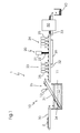
- FIG. 1 a schematic representation of a first coating unit for executing an exemplary embodiment of the method according to the invention with separate drying and joint annealing of two coating agent layers and
- FIG. 2 a schematic representation of a second coating unit for executing an exemplary embodiment of the method according to the invention with joint drying and joint annealing of two coating agent layers.
- the coating unit 1 shown in FIG. 1 for executing a method according to the state of the art comprises as main elements a first coating station 10 for the application of a first layer of coating agent, a first drying station 23 for the drying of the first layer, a second coating station 20 for the application of a second layer of coating agent, a second drying station 24 for drying the second layer as well as a convection oven 50 for the annealing of the coating agent.
- the first coating station 10 comprises a dipping tank 11 , in which a coating bath 12 of a base coat, i.e. of an anticorrosive, liquid, metal-particle-containing coating means, is located.
- a first conveyor belt 30 which leads to the dipping tank 11 , serves to bring in workpieces 2 .
- a second conveyor belt 31 leads out of the dipping tank 11 .
- the conveying direction of the second conveyor belt 31 does not run horizontal, but rather diagonally upward.
- the second conveyor belt 31 has a surface structure with a series of webs (not shown) located diagonally to the conveying direction.
- the second conveyor belt 31 runs through the coating bath 12 in the shown operating state of the unit 1 in a lower area 34 . It runs through an upper area 35 below a blowing station 13 and ends above a third conveyor belt 32 , which is in turn aligned horizontally.
- the third conveyor belt 32 passes one after the other through the first drying station 23 , the second coating station 20 , which comprises a pouring device 21 arranged within the second conveyor belt 32 , as well as the second drying station 24 .
- Each of the drying stations 23 , 24 is formed by a series of hot air blowers 25 , which are pointed toward the third conveyor belt 32 .
- a fourth conveyor belt 33 is connected to the third conveyor belt 32 , which runs through the convection oven 50 .
- Both the second and the third conveyor belt 32 are designed as a sieve, whereby a flowing off of liquid coating agent is enabled.
- Steel screws 2 are provided for coating in the shown unit 1 .
- they are previously degreased at 75° C. in a cleaning solution composed of water in which 1 liter water, 9 g of potassium phosphate and 27 g potassium hydroxide were dissolved, and then cleaned with tap water. The degreasing and cleaning procedure is repeated again and the screws are then dried.
- the screws 2 are given to the second conveyor belt 30 , which runs with a speed of 10 cm/s. At the end of the first conveyor belt 30 , the screws 2 fall into the coating bath 12 , which in the present case has the following composition:
- the flake-shaped metal particles have a thickness of approximately 0.1 to 0.5 ⁇ m and a longest dimension of the individual particle of approximately 80 ⁇ m. They are made of an alloy of 95% zinc with 5% aluminum.
- the arrangement of the first 30 and second conveyor belt 31 is hereby such that the screws 2 land on the second conveyor belt 31 .
- the screws 2 are conveyed by the second conveyor belt 31 , which is also operated at 10 cm/s, diagonally upward out of the dipping tank 11 , whereby excess coating agent can run off the screws 2 through the open structure of the conveyor belt 31 .
- the screws 3 now have a first layer of coating agent.
- liquid is blown off the screws 2 by the blowing station 13 , which generates a cold air flow of approximately 20 m/s.
- the screws 2 fall onto the third conveyor belt 32 , which is operated at a speed of 30 cm/s. Further separation occurs through the associated acceleration of the screws 2 .
- the screws 2 now run through the first drying station 23 .
- This comprises a series of hot air blowers 25 , which generate air flows of approximately 5 m/s and 70° C. The drying takes 4-5 seconds.
- liquid components of the coating means are largely evaporated, whereupon the first layer is dried until it is no longer removed or damaged without a strong mechanical action.
- the pouring station 21 has a series of outlet openings (not shown) for a coating agent, which in this case is identical to that in the dipping tank 11 .
- the pouring device 21 generates a very tight pouring curtain 22 , through which a normally seamless application of second coating agent to the first layer of coating agent takes place.
- the screws 2 While the screws 2 are transported on, excess coating means runs off due to the sieve structure of the third conveyor belt 32 .
- the running off coating agent is caught in a reservoir 26 and can be reused.
- the screws 2 run through the second drying station 24 .
- This also includes hot air blowers 25 , the structure and operating parameters of which correspond with those of the first drying station 23 . After passing through the second drying station 24 , the second layer is also dry.
- the screws 2 fall onto the fourth conveyor belt 33 , which is operated at 2 cm/s.
- the separation of the screws 2 is hereby reversed, but this is insignificant since the coating agent is dry and no further coating takes place.
- the screws 2 now run through the convection oven 50 , where both layers of the coating agent are annealed at 320° C.
- the screws 2 fall into a container 40 , by means of which they can be transported away.
- FIG. 2 shows a second coating unit 1 ′ for executing the method according to the invention.
- This also comprises a first coating station 10 for the application of a first layer of coating agent as well as a second coating station 20 for the application of a second layer of coating agent.
- a separate drying station 27 is provided here, which is located upstream of a convection oven 50 for the annealing of the coating agent.
- this coating device 1 ′ is largely identical to that of the device 1 shown in FIG. 1 . Thus, a detailed explanation of the individual elements as well as the operating mode is omitted if they match.
- the third conveyor belt 32 runs through the second coating station 20 as well as the drying station 27 ; thus, a drying device is not located upstream of the second coating station 20 .
- the drying station 27 is formed in turn by a series of hot air blowers 25 , which are pointed toward the third conveyor belt 32 .
- the screws 2 are now transported on the third conveyor belt 32 below and through the pouring device 21 of the second coating station 20 without being previously dried. With this device 1 ′, both layers of coating agent are rather dried jointly. For this, the screws 2 run through the drying station 27 after the second coating station 20 . Structure and operating parameters of the hot air blowers 25 correspond with those of drying stations 23 , 24 of the first exemplary embodiment. After passing through the drying station 27 , both layers are dried enough so that they are no longer removed or damaged without a strong mechanical action.
- Both layers are then jointly annealed in the convection oven 50 .
Landscapes
- Life Sciences & Earth Sciences (AREA)
- Engineering & Computer Science (AREA)
- Wood Science & Technology (AREA)
- Chemical & Material Sciences (AREA)
- Materials Engineering (AREA)
- Organic Chemistry (AREA)
- Application Of Or Painting With Fluid Materials (AREA)
- Coating Apparatus (AREA)
- Other Surface Treatments For Metallic Materials (AREA)
Applications Claiming Priority (3)
| Application Number | Priority Date | Filing Date | Title |
|---|---|---|---|
| DE102009034869.7 | 2009-07-27 | ||
| DE102009034869A DE102009034869A1 (de) | 2009-07-27 | 2009-07-27 | Verfahren zum Auftragen wenigstens eines antikorrosiven, flüssigen, Metallpartikel enthaltenden Beschichtungsmittels auf ein Werkstück sowie eine Vorrichtung hierfür |
| PCT/EP2010/059998 WO2011012434A1 (fr) | 2009-07-27 | 2010-07-12 | Procédé pour appliquer au moins une composition de revêtement anticorrosive, liquide, contenant des particules métalliques, sur une pièce à travailler, ainsi qu'un dispositif pour la mise en uvre de ce procédé |
Publications (1)
| Publication Number | Publication Date |
|---|---|
| US20120183791A1 true US20120183791A1 (en) | 2012-07-19 |
Family
ID=42829459
Family Applications (1)
| Application Number | Title | Priority Date | Filing Date |
|---|---|---|---|
| US13/387,383 Abandoned US20120183791A1 (en) | 2009-07-27 | 2010-07-12 | Method for applying at least one anti-corrosive, liquid coating agent comprising metal particles to a workpiece, and device therefor |
Country Status (13)
| Country | Link |
|---|---|
| US (1) | US20120183791A1 (fr) |
| EP (1) | EP2464461A1 (fr) |
| JP (1) | JP2013500154A (fr) |
| KR (1) | KR20120049266A (fr) |
| CN (1) | CN102639256A (fr) |
| AU (1) | AU2010278169A1 (fr) |
| CA (1) | CA2770859A1 (fr) |
| DE (1) | DE102009034869A1 (fr) |
| EA (1) | EA201270196A1 (fr) |
| IL (1) | IL217775A0 (fr) |
| MX (1) | MX2012001171A (fr) |
| WO (1) | WO2011012434A1 (fr) |
| ZA (1) | ZA201200685B (fr) |
Cited By (1)
| Publication number | Priority date | Publication date | Assignee | Title |
|---|---|---|---|---|
| US12606144B2 (en) | 2019-12-27 | 2026-04-21 | Cooper-Standard Automotive (Deutschland) Gmbh | Union screw for a pipeline provided with at least one flange, in particular a brake pipe |
Families Citing this family (13)
| Publication number | Priority date | Publication date | Assignee | Title |
|---|---|---|---|---|
| JP5750318B2 (ja) * | 2011-06-29 | 2015-07-22 | ローバル株式会社 | 水性塗料及びこれを使用する補修方法 |
| DE102012215512A1 (de) † | 2012-08-31 | 2014-05-28 | Bayerische Motoren Werke Aktiengesellschaft | Verfahren und Fertigungsanlage zum Herstellen eines warmumgeformten oder pressgehärteten Blechformteils mit einer metallischen Korrosionsschutzbeschichtung sowie hiermit hergestelltes Blechformteil und Fahrzeugkarosserie mit solchem Blechformteil |
| DE102013216415A1 (de) * | 2013-08-19 | 2015-02-19 | Mep-Olbo Gmbh | Vorrichtung und Verfahren zur Beschichtung eines Substrats |
| KR101735820B1 (ko) * | 2015-07-20 | 2017-05-15 | 창원대학교 산학협력단 | 메탈잉크 프린팅 장치, 방법 및 메탈잉크 코팅 강판 |
| KR101681549B1 (ko) * | 2016-01-06 | 2016-12-01 | 장철현 | 방청용 표면처리 시스템 및 방법 |
| KR101686419B1 (ko) * | 2016-01-06 | 2016-12-14 | 장철현 | 방청용 표면처리 시스템 및 방법 |
| CN105537046A (zh) * | 2016-03-09 | 2016-05-04 | 佳马机械涂覆科技(苏州)有限公司 | 一种汽车气门的防锈处理线 |
| EP3243878A1 (fr) | 2016-05-10 | 2017-11-15 | Rembrandtin Lack GmbH Nfg.KG | Protection anti-corrosion |
| DE102017116514A1 (de) * | 2017-07-21 | 2019-01-24 | Schaeffler Technologies AG & Co. KG | Radlageranordnung mit einer Beschichtung |
| CN108246588A (zh) * | 2018-01-12 | 2018-07-06 | 江苏宏宝锻造股份有限公司 | 发动机连杆的防锈工艺及其红外烘道装置 |
| CN108408328B (zh) * | 2018-02-11 | 2023-05-09 | 南京诺淳五金制品有限公司 | 一种排钉上漆的方法 |
| DE102019213258A1 (de) * | 2019-09-03 | 2021-03-04 | Zf Friedrichshafen Ag | Verfahren zur Ausbildung einer einen Korrosionsschutz bildenden Beschichtung auf einer aktiven Fahrwerkeinrichtung, insbesondere einem Wankstabilisator für ein Kraftfahrzeug |
| CN115155979B (zh) * | 2022-09-07 | 2022-11-25 | 常州铭赛机器人科技股份有限公司 | 磁胶出胶精度高的螺杆阀及其出胶控制方法 |
Citations (1)
| Publication number | Priority date | Publication date | Assignee | Title |
|---|---|---|---|---|
| US20080193743A1 (en) * | 2004-07-16 | 2008-08-14 | Thomas Kruse | Corrosion Control Coating Composition For Metal Workpieces and Method of Producing Same |
Family Cites Families (17)
| Publication number | Priority date | Publication date | Assignee | Title |
|---|---|---|---|---|
| JPS5822269B2 (ja) * | 1980-05-15 | 1983-05-07 | 株式会社クボタ | 複合塗膜の形成方法 |
| JPS6418476A (en) * | 1987-07-14 | 1989-01-23 | Honda Motor Co Ltd | Rust-prevention treatment of inside of petrol tank made of metal |
| JP2599467B2 (ja) * | 1989-10-17 | 1997-04-09 | 関西ペイント株式会社 | 亜鉛めっき鋼材の表面処理方法および表面処理組成物 |
| US5114751A (en) * | 1989-10-24 | 1992-05-19 | Henkel Corporation | Application of an organic coating to small metal articles |
| ZA908312B (en) * | 1989-10-24 | 1991-08-28 | Henkel Corp | Application of an organic coating to small metallic articles |
| EP0525870B1 (fr) * | 1991-07-22 | 1994-09-07 | Akzo Nobel N.V. | Revêtement en poudre contenant une résine, un agent réticulant et du zinc |
| JPH0924332A (ja) * | 1995-07-12 | 1997-01-28 | Nishi Nippon Rejikooto Kk | 防錆塗装方法 |
| DE19703489A1 (de) * | 1996-11-13 | 1998-05-14 | Doerken Ewald Ag | Verfahren zum Aufbringen einer anorganischen Beschichtung auf einen elektrisch leitfähigen Körper |
| JP3504872B2 (ja) * | 1998-11-20 | 2004-03-08 | 東西化学株式会社 | 塗膜、ならびに塗膜の形成方法 |
| FR2800390B1 (fr) * | 1999-11-02 | 2002-01-11 | Dacral Sa | Procede et dispositif d'application d'un revetement anti-corrosion |
| WO2002007090A2 (fr) * | 2000-07-13 | 2002-01-24 | Fitracks Inc. | Procede et systeme d'achat de marchandises |
| US6676820B2 (en) * | 2001-03-02 | 2004-01-13 | Ppg Industries Ohio, Inc. | Process for electrocoating metal blanks and coiled metal substrates |
| DE602004001309T2 (de) * | 2003-10-10 | 2007-05-31 | Rohm And Haas Co. | Grundierungsfreie Beschichtung von wärmeempfindlichen Substraten und Beschichtungsstrasse |
| MXPA06010676A (es) * | 2004-03-19 | 2007-02-21 | Doerken Ewald Ag | Microrevestimiento comprendiendo siloxanos. |
| US7455732B2 (en) * | 2004-08-13 | 2008-11-25 | Ppg Industries Ohio, Inc. | Apparatus and systems for coating objects |
| WO2006020857A2 (fr) * | 2004-08-13 | 2006-02-23 | Ppg Industries Ohio, Inc. | Appareil et systemes pour le revetement d'objets |
| DE102006012103A1 (de) * | 2006-03-14 | 2007-09-20 | Ewald Dörken Ag | Verfahren zum Beschichten von Werkstücken und Vorrichtung hierfür |
-
2009
- 2009-07-27 DE DE102009034869A patent/DE102009034869A1/de not_active Ceased
-
2010
- 2010-07-12 CN CN2010800407111A patent/CN102639256A/zh active Pending
- 2010-07-12 WO PCT/EP2010/059998 patent/WO2011012434A1/fr not_active Ceased
- 2010-07-12 MX MX2012001171A patent/MX2012001171A/es not_active Application Discontinuation
- 2010-07-12 EP EP10739532A patent/EP2464461A1/fr not_active Withdrawn
- 2010-07-12 AU AU2010278169A patent/AU2010278169A1/en not_active Abandoned
- 2010-07-12 KR KR20127003952A patent/KR20120049266A/ko not_active Withdrawn
- 2010-07-12 CA CA2770859A patent/CA2770859A1/fr not_active Abandoned
- 2010-07-12 US US13/387,383 patent/US20120183791A1/en not_active Abandoned
- 2010-07-12 JP JP2012522081A patent/JP2013500154A/ja active Pending
- 2010-07-12 EA EA201270196A patent/EA201270196A1/ru unknown
-
2012
- 2012-01-26 IL IL217775A patent/IL217775A0/en unknown
- 2012-01-27 ZA ZA2012/00685A patent/ZA201200685B/en unknown
Patent Citations (1)
| Publication number | Priority date | Publication date | Assignee | Title |
|---|---|---|---|---|
| US20080193743A1 (en) * | 2004-07-16 | 2008-08-14 | Thomas Kruse | Corrosion Control Coating Composition For Metal Workpieces and Method of Producing Same |
Cited By (1)
| Publication number | Priority date | Publication date | Assignee | Title |
|---|---|---|---|---|
| US12606144B2 (en) | 2019-12-27 | 2026-04-21 | Cooper-Standard Automotive (Deutschland) Gmbh | Union screw for a pipeline provided with at least one flange, in particular a brake pipe |
Also Published As
| Publication number | Publication date |
|---|---|
| DE102009034869A1 (de) | 2011-02-03 |
| EA201270196A1 (ru) | 2012-08-30 |
| CA2770859A1 (fr) | 2011-02-03 |
| MX2012001171A (es) | 2012-05-08 |
| WO2011012434A1 (fr) | 2011-02-03 |
| IL217775A0 (en) | 2012-03-29 |
| JP2013500154A (ja) | 2013-01-07 |
| KR20120049266A (ko) | 2012-05-16 |
| EP2464461A1 (fr) | 2012-06-20 |
| AU2010278169A1 (en) | 2012-03-01 |
| CN102639256A (zh) | 2012-08-15 |
| ZA201200685B (en) | 2012-09-26 |
Similar Documents
| Publication | Publication Date | Title |
|---|---|---|
| CA2770859A1 (fr) | Procede pour appliquer au moins une composition de revetement anticorrosive, liquide, contenant des particules metalliques, sur une piece a travailler, ainsi qu'un dispositif pourla mise en ?uvre de ce procede | |
| JP5957015B2 (ja) | 鋼板製品、鋼板製品の製造方法及び部品の製造方法 | |
| EP1877598A1 (fr) | Reparation et recharge effectuees avec du magnesium | |
| JP2014506959A5 (fr) | ||
| CN102853209A (zh) | 聚四氟乙烯在开采原油设备中的应用 | |
| TWI716170B (zh) | 無酸磷化金屬板材的處理方法 | |
| CN105327843A (zh) | 金属表面前处理及喷塑的流水线生产工艺 | |
| EP2703454A1 (fr) | Compositions de revêtement | |
| CN101392360A (zh) | 重型汽车排气管热浸渗铝的工艺方法 | |
| JP6846741B2 (ja) | アルミダイカスト品の絶縁塗装方法 | |
| CN114713483A (zh) | 球墨铸铁管表面喷锌防腐处理工艺 | |
| PL234275B1 (pl) | Sposób malowania proszkowego ocynkowanych ogniowo elementów stalowych | |
| RU2659547C1 (ru) | Способ получения антикоррозионного покрытия на металлическом изделии (варианты) | |
| CN107457167A (zh) | 一种达克罗处理工艺流程 | |
| JPH0924332A (ja) | 防錆塗装方法 | |
| JP2003138400A (ja) | 電着塗料の二次タレ防止方法 | |
| CN108486620A (zh) | 一种锌合金工件内腔止镀的方法 | |
| CN107829060A (zh) | 输电线路杆塔长效防腐的方法 | |
| CN107199160A (zh) | 一种工件涂装生产线及达克罗涂装工艺 | |
| JPH08173896A (ja) | 防錆塗装方法 | |
| RU2606774C2 (ru) | Способ получения компактного слоя эмалевых покрытий на литых изделиях | |
| Noon | Industrial painting techniques | |
| BE1031212A1 (nl) | Werkwijze voor het poederlakken van geëxtrudeerde profielen | |
| CN116393347A (zh) | 一种聚四氟乙烯改性耐磨烤漆喷涂工艺 | |
| CN101992183A (zh) | 金属表面粉末喷涂新工艺 |
Legal Events
| Date | Code | Title | Description |
|---|---|---|---|
| AS | Assignment |
Owner name: EWALD DOERKEN AG, GERMANY Free format text: ASSIGNMENT OF ASSIGNORS INTEREST;ASSIGNORS:REUSMANN, GERHARD, DR.;KRUSE, THOMAS;RABE, CHRISTIAN;AND OTHERS;SIGNING DATES FROM 20120206 TO 20120207;REEL/FRAME:027997/0137 |
|
| STCB | Information on status: application discontinuation |
Free format text: ABANDONED -- FAILURE TO RESPOND TO AN OFFICE ACTION |