US20200047556A1 - Tire - Google Patents
Tire Download PDFInfo
- Publication number
- US20200047556A1 US20200047556A1 US16/340,377 US201716340377A US2020047556A1 US 20200047556 A1 US20200047556 A1 US 20200047556A1 US 201716340377 A US201716340377 A US 201716340377A US 2020047556 A1 US2020047556 A1 US 2020047556A1
- Authority
- US
- United States
- Prior art keywords
- tire
- resin
- axial direction
- covered cord
- cord
- Prior art date
- Legal status (The legal status is an assumption and is not a legal conclusion. Google has not performed a legal analysis and makes no representation as to the accuracy of the status listed.)
- Abandoned
Links
- 229920005989 resin Polymers 0.000 claims abstract description 51
- 239000011347 resin Substances 0.000 claims abstract description 51
- 230000003014 reinforcing effect Effects 0.000 claims abstract description 21
- 229920002725 thermoplastic elastomer Polymers 0.000 claims description 17
- 239000011324 bead Substances 0.000 description 20
- 239000000463 material Substances 0.000 description 18
- 230000002093 peripheral effect Effects 0.000 description 17
- 238000001816 cooling Methods 0.000 description 12
- 229920001971 elastomer Polymers 0.000 description 11
- 229920005992 thermoplastic resin Polymers 0.000 description 8
- 238000004804 winding Methods 0.000 description 8
- 238000003825 pressing Methods 0.000 description 7
- 239000000806 elastomer Substances 0.000 description 6
- 239000000835 fiber Substances 0.000 description 6
- 238000000034 method Methods 0.000 description 5
- 239000005060 rubber Substances 0.000 description 5
- 229920001169 thermoplastic Polymers 0.000 description 5
- 150000001875 compounds Chemical class 0.000 description 4
- 238000004519 manufacturing process Methods 0.000 description 4
- 229920000642 polymer Polymers 0.000 description 4
- 229920001187 thermosetting polymer Polymers 0.000 description 4
- 239000004416 thermosoftening plastic Substances 0.000 description 4
- 239000002184 metal Substances 0.000 description 3
- 229910052751 metal Inorganic materials 0.000 description 3
- 229920002397 thermoplastic olefin Polymers 0.000 description 3
- 229920006345 thermoplastic polyamide Polymers 0.000 description 3
- 238000003466 welding Methods 0.000 description 3
- XEEYBQQBJWHFJM-UHFFFAOYSA-N Iron Chemical compound [Fe] XEEYBQQBJWHFJM-UHFFFAOYSA-N 0.000 description 2
- 239000004793 Polystyrene Substances 0.000 description 2
- 239000004433 Thermoplastic polyurethane Substances 0.000 description 2
- -1 cord Substances 0.000 description 2
- 230000000694 effects Effects 0.000 description 2
- 229920006351 engineering plastic Polymers 0.000 description 2
- 238000010438 heat treatment Methods 0.000 description 2
- 239000007788 liquid Substances 0.000 description 2
- 229920002223 polystyrene Polymers 0.000 description 2
- 229920002803 thermoplastic polyurethane Polymers 0.000 description 2
- 229920000877 Melamine resin Polymers 0.000 description 1
- 229910000831 Steel Inorganic materials 0.000 description 1
- 229920001807 Urea-formaldehyde Polymers 0.000 description 1
- BZHJMEDXRYGGRV-UHFFFAOYSA-N Vinyl chloride Chemical compound ClC=C BZHJMEDXRYGGRV-UHFFFAOYSA-N 0.000 description 1
- NIXOWILDQLNWCW-UHFFFAOYSA-N acrylic acid group Chemical group C(C=C)(=O)O NIXOWILDQLNWCW-UHFFFAOYSA-N 0.000 description 1
- 239000000853 adhesive Substances 0.000 description 1
- 230000001070 adhesive effect Effects 0.000 description 1
- 238000004873 anchoring Methods 0.000 description 1
- 230000008878 coupling Effects 0.000 description 1
- 238000010168 coupling process Methods 0.000 description 1
- 238000005859 coupling reaction Methods 0.000 description 1
- 239000003822 epoxy resin Substances 0.000 description 1
- LNEPOXFFQSENCJ-UHFFFAOYSA-N haloperidol Chemical compound C1CC(O)(C=2C=CC(Cl)=CC=2)CCN1CCCC(=O)C1=CC=C(F)C=C1 LNEPOXFFQSENCJ-UHFFFAOYSA-N 0.000 description 1
- 238000002347 injection Methods 0.000 description 1
- 239000007924 injection Substances 0.000 description 1
- 229910052742 iron Inorganic materials 0.000 description 1
- 239000000155 melt Substances 0.000 description 1
- 238000002844 melting Methods 0.000 description 1
- 230000008018 melting Effects 0.000 description 1
- 238000012986 modification Methods 0.000 description 1
- 230000004048 modification Effects 0.000 description 1
- 239000004745 nonwoven fabric Substances 0.000 description 1
- 229920001568 phenolic resin Polymers 0.000 description 1
- 239000005011 phenolic resin Substances 0.000 description 1
- 229920000647 polyepoxide Polymers 0.000 description 1
- 229920000728 polyester Polymers 0.000 description 1
- 229920001225 polyester resin Polymers 0.000 description 1
- 229920001296 polysiloxane Polymers 0.000 description 1
- 230000005855 radiation Effects 0.000 description 1
- 239000012779 reinforcing material Substances 0.000 description 1
- 238000007789 sealing Methods 0.000 description 1
- 239000000243 solution Substances 0.000 description 1
- 239000010959 steel Substances 0.000 description 1
- 239000012815 thermoplastic material Substances 0.000 description 1
- 238000004073 vulcanization Methods 0.000 description 1
- 239000004636 vulcanized rubber Substances 0.000 description 1
- XLYOFNOQVPJJNP-UHFFFAOYSA-N water Substances O XLYOFNOQVPJJNP-UHFFFAOYSA-N 0.000 description 1
- 239000002759 woven fabric Substances 0.000 description 1
Images




Classifications
-
- B—PERFORMING OPERATIONS; TRANSPORTING
- B60—VEHICLES IN GENERAL
- B60C—VEHICLE TYRES; TYRE INFLATION; TYRE CHANGING; CONNECTING VALVES TO INFLATABLE ELASTIC BODIES IN GENERAL; DEVICES OR ARRANGEMENTS RELATED TO TYRES
- B60C5/00—Inflatable pneumatic tyres or inner tubes
- B60C5/007—Inflatable pneumatic tyres or inner tubes made from other material than rubber
-
- B—PERFORMING OPERATIONS; TRANSPORTING
- B60—VEHICLES IN GENERAL
- B60C—VEHICLE TYRES; TYRE INFLATION; TYRE CHANGING; CONNECTING VALVES TO INFLATABLE ELASTIC BODIES IN GENERAL; DEVICES OR ARRANGEMENTS RELATED TO TYRES
- B60C9/00—Reinforcements or ply arrangement of pneumatic tyres
- B60C9/18—Structure or arrangement of belts or breakers, crown-reinforcing or cushioning layers
- B60C9/20—Structure or arrangement of belts or breakers, crown-reinforcing or cushioning layers built-up from rubberised plies each having all cords arranged substantially parallel
- B60C9/22—Structure or arrangement of belts or breakers, crown-reinforcing or cushioning layers built-up from rubberised plies each having all cords arranged substantially parallel the plies being arranged with all cords disposed along the circumference of the tyre
- B60C9/2204—Structure or arrangement of belts or breakers, crown-reinforcing or cushioning layers built-up from rubberised plies each having all cords arranged substantially parallel the plies being arranged with all cords disposed along the circumference of the tyre obtained by circumferentially narrow strip winding
-
- B—PERFORMING OPERATIONS; TRANSPORTING
- B60—VEHICLES IN GENERAL
- B60C—VEHICLE TYRES; TYRE INFLATION; TYRE CHANGING; CONNECTING VALVES TO INFLATABLE ELASTIC BODIES IN GENERAL; DEVICES OR ARRANGEMENTS RELATED TO TYRES
- B60C5/00—Inflatable pneumatic tyres or inner tubes
- B60C5/01—Inflatable pneumatic tyres or inner tubes without substantial cord reinforcement, e.g. cordless tyres, cast tyres
-
- B—PERFORMING OPERATIONS; TRANSPORTING
- B60—VEHICLES IN GENERAL
- B60C—VEHICLE TYRES; TYRE INFLATION; TYRE CHANGING; CONNECTING VALVES TO INFLATABLE ELASTIC BODIES IN GENERAL; DEVICES OR ARRANGEMENTS RELATED TO TYRES
- B60C9/00—Reinforcements or ply arrangement of pneumatic tyres
- B60C9/18—Structure or arrangement of belts or breakers, crown-reinforcing or cushioning layers
- B60C9/20—Structure or arrangement of belts or breakers, crown-reinforcing or cushioning layers built-up from rubberised plies each having all cords arranged substantially parallel
- B60C9/22—Structure or arrangement of belts or breakers, crown-reinforcing or cushioning layers built-up from rubberised plies each having all cords arranged substantially parallel the plies being arranged with all cords disposed along the circumference of the tyre
-
- B—PERFORMING OPERATIONS; TRANSPORTING
- B60—VEHICLES IN GENERAL
- B60C—VEHICLE TYRES; TYRE INFLATION; TYRE CHANGING; CONNECTING VALVES TO INFLATABLE ELASTIC BODIES IN GENERAL; DEVICES OR ARRANGEMENTS RELATED TO TYRES
- B60C9/00—Reinforcements or ply arrangement of pneumatic tyres
- B60C9/18—Structure or arrangement of belts or breakers, crown-reinforcing or cushioning layers
- B60C9/20—Structure or arrangement of belts or breakers, crown-reinforcing or cushioning layers built-up from rubberised plies each having all cords arranged substantially parallel
- B60C2009/2035—Structure or arrangement of belts or breakers, crown-reinforcing or cushioning layers built-up from rubberised plies each having all cords arranged substantially parallel built-up by narrow strips
-
- B—PERFORMING OPERATIONS; TRANSPORTING
- B60—VEHICLES IN GENERAL
- B60C—VEHICLE TYRES; TYRE INFLATION; TYRE CHANGING; CONNECTING VALVES TO INFLATABLE ELASTIC BODIES IN GENERAL; DEVICES OR ARRANGEMENTS RELATED TO TYRES
- B60C9/00—Reinforcements or ply arrangement of pneumatic tyres
- B60C9/18—Structure or arrangement of belts or breakers, crown-reinforcing or cushioning layers
- B60C9/20—Structure or arrangement of belts or breakers, crown-reinforcing or cushioning layers built-up from rubberised plies each having all cords arranged substantially parallel
- B60C2009/2045—Structure or arrangement of belts or breakers, crown-reinforcing or cushioning layers built-up from rubberised plies each having all cords arranged substantially parallel with belt joints or splices
-
- B—PERFORMING OPERATIONS; TRANSPORTING
- B60—VEHICLES IN GENERAL
- B60C—VEHICLE TYRES; TYRE INFLATION; TYRE CHANGING; CONNECTING VALVES TO INFLATABLE ELASTIC BODIES IN GENERAL; DEVICES OR ARRANGEMENTS RELATED TO TYRES
- B60C9/00—Reinforcements or ply arrangement of pneumatic tyres
- B60C9/18—Structure or arrangement of belts or breakers, crown-reinforcing or cushioning layers
- B60C9/20—Structure or arrangement of belts or breakers, crown-reinforcing or cushioning layers built-up from rubberised plies each having all cords arranged substantially parallel
- B60C9/22—Structure or arrangement of belts or breakers, crown-reinforcing or cushioning layers built-up from rubberised plies each having all cords arranged substantially parallel the plies being arranged with all cords disposed along the circumference of the tyre
- B60C2009/2238—Physical properties or dimensions of the ply coating rubber
Definitions
- the present disclosure relates to a tire.
- JP-A No. 2014-210487 discloses a tire including a belt layer in which a reinforcing cord member configured by a reinforcing cord covered by a covering resin is wound onto an outer periphery of a tire frame member in a spiral pattern around the tire circumferential direction, and bonded to the tire frame member.
- the reinforcing cord member has a rectangular cross-section. Accordingly, the degree of bonding with the tire frame member is sufficient. However, there is still room for improvement of the degree of mutual bonding between sections of the reinforcing cord member that are adjacent in a tire axial direction.
- An object of the present disclosure is to improve the durability of a tire including a belt layer configured by winding a resin-covered cord in a spiral pattern.
- a tire according to the present disclosure includes a ring-shaped tire frame member, and a belt layer that is provided at an outer periphery of the tire frame member, and in which a resin-covered cord, which is configured by covering a reinforcing cord with a covering resin is wound onto the outer periphery of the tire frame member in a spiral pattern around a tire circumferential direction and is bonded to the tire frame member, with sections of the resin-covered cord that are mutually adjacent in a tire axial direction being bonded to each other.
- An end portion at one tire axial direction side of a tire radial direction outside face of the resin-covered cord is positioned further toward the one tire axial direction side than an end portion at the one tire axial direction side of a tire radial direction inside face of the resin-covered cord, and an end portion at another tire axial direction side of the outside face is positioned further toward the one tire axial direction side than an end portion at the other tire axial direction side of the inside face.
- the present disclosure enables the durability of a tire including a belt layer configured by winding a resin-covered cord in a spiral pattern to be improved.
- FIG. 1 is a cross-section illustrating a tire according to an exemplary embodiment.
- FIG. 2 is a perspective cross-section illustrating a process for winding a resin-covered cord onto a tire case.
- FIG. 3 is a side view illustrating a state in which a resin-covered cord has been pressed against an outer periphery of a tire frame member by a press roller.
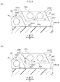
- FIG. 4(A) and FIG. 4(B) are cross-sections illustrating a section of resin-covered cord that has been pressed against an outer periphery of a tire frame member and the next section of resin-covered cord to be pressed against the outer periphery of the tire frame member.
- FIG. 4(A) illustrates an example in which the resin-covered cord has a parallelogram shaped cross-section profile.
- FIG. 4(B) illustrates an example in which an incline angle of a side face of one section of the resin-covered cord is different to an incline angle of a side face of another section of resin-covered cord that is adjacent in the tire axial direction.
- FIG. 5 is a cross-section illustrating a state in which a resin-covered cord is pressed against an outer periphery of a tire frame member by a press roller.
- FIG. 6 is a cross-section illustrating an example in which the press roller illustrated in FIG. 5 is provided with a guide section.
- FIG. 7(A) to FIG. 7(D) are cross-sections illustrating modified examples of a resin-covered cord.
- a tire circumferential direction is indicated by an arrow S
- a tire axial direction (which may also be understood as a tire width direction) is indicated by an arrow W
- a tire radial direction is indicated by an arrow R.
- the tire axial direction refers to a direction parallel to the axis of rotation of the tire.
- the sides further from a tire equatorial plane CL along the tire axial direction are referred to as the “tire axial direction outsides” and the side closer toward the tire equatorial plane CL along the tire axial direction is referred to as the “tire axial direction inside”.
- the side further from a tire axis in the tire radial direction is referred to as the “tire radial direction outside”
- the side closer to the tire axis in the tire radial direction is referred to as the “tire radial direction inside”.
- the methods for measuring the dimensions of the respective sections are the methods set out in the 2016 Year Book issued by the Japan Automobile Tire Manufacturers Association (JATMA). In cases in which TRA standards or ETRTO standards apply in the place of use or place of manufacture, these standards are followed.
- a tire 10 As illustrated in FIG. 1 , a tire 10 according to the present exemplary embodiment includes a tire case 17 serving as an example of a circular ring-shaped tire frame member, and a belt layer 12 .
- the tire case 17 may be a tire case for a rubber tire including a carcass ply (not illustrated in the drawings).
- the tire case 17 is configured by a thermoplastic elastomer serving as an example of a resin material for a tire frame.
- the tire case 17 is formed in a circular ring shape around the tire circumferential direction.
- the tire case 17 is configured including a pair of bead portions 14 disposed spaced apart from each other in the tire axial direction, a pair of side portions 16 extending from the pair of bead portions 14 toward the tire radial direction outside, and a crown portion 18 coupling together the pair of side portions 16 .
- the bead portions 14 are locations that contact a rim (not illustrated in the drawings), and a covering layer 22 , described later, is provided on the surface of each of the bead portions 14 .
- the side portions 16 are formed at side portions of the tire 10 , and curve gently so as to protrude toward the tire axial direction outsides on progression from the bead portions 14 toward the crown portion 18 .
- the crown portion 18 is a location that couples a tire radial direction outer end of one of the side portions 16 and a tire radial direction outer end of the other of the side portions 16 together, and supports a tread 30 laid at the tire radial direction outside of the crown portion 18 .
- the crown portion 18 has a substantially uniform thickness.
- An outer peripheral face 18 A may be formed with a flat profile in cross-section taken along the tire axial direction, or may have a curving profile bulging toward the tire radial direction outside. Note that the outer peripheral face 18 A of the crown portion 18 of the present exemplary embodiment configures an outer periphery of the tire case 17 to which the belt layer 12 is provided.
- the tire case 17 is formed by forming a pair of annular tire halves 17 H, each including a single bead portion 14 , a single side portion 16 , and a half-width crown portion 18 .
- the tire halves 17 H are made to face each other and end portions of the half-width crown portions 18 are bonded together at the tire equatorial plane CL.
- the end portions are bonded together using, for example, a resin welding material 17 A.
- the bead core 20 is configured from a bead cord (not illustrated in the drawings).
- the bead cord is, for example configured by a metal cord such as a steel cord, an organic fiber cord, a resin-covered organic fiber cord, or a hard resin. Note that the bead core 20 itself may be omitted as long as sufficient rigidity of the bead portion 14 can be secured.
- each of the bead portions 14 at least a portion that contacts the rim (not illustrated in the drawings) is formed with the covering layer 22 in order to increase the airtightness against the rim.
- the covering layer 22 is configured from a material such as a rubber material that is softer and more weather-resistant than the tire case 17 .
- the covering layer 22 is folded back from an inner face at the tire axial direction inside of each of the bead portions 14 toward the tire axial direction outside, and extends across an outer face of the side portion 16 to the vicinity of a tire axial direction outside end portion 12 A of the belt layer 12 .
- An extension end portion of the covering layer 22 is covered by cushion rubber 32 , described later, and the tread 30 .
- the covering layer 22 may be omitted if sealing properties (airtightness) between the bead portion 14 and the rim (not illustrated in the drawings) can be secured by the bead portion 14 of the tire case 17 alone.
- the tire case 17 may be configured by an integrally molded article, or the tire case 17 may be manufactured as three or more separate resin members which are then bonded together.
- respective locations of the tire case 17 for example the bead portions 14 , the side portions 16 , and the crown portion 18
- respective locations of the tire case 17 may be manufactured separately and then bonded together.
- the respective locations of the tire case 17 may be formed using resin materials with different characteristics to each other.
- Reinforcing material (polymer or metal fibers, cord, nonwoven fabric, woven fabric, or the like) may be embedded in the tire case 17 .
- the belt layer 12 is provided at the outer periphery of the tire case 17 .
- the outer periphery of the tire case 17 corresponds to the outer peripheral face 18 A of the crown portion 18 .
- a resin-covered cord 28 is wound onto the outer periphery of the tire case 17 in a spiral pattern around the tire circumferential direction and is bonded to the tire case 17 , and sections of the resin-covered cord 28 that are mutually adjacent in the tire axial direction are bonded to one another.
- the resin-covered cord 28 is configured by covering a reinforcing cord 24 with a covering resin 26 . As illustrated in FIG. 4 and FIG.
- sections of the resin-covered cord 28 that are mutually adjacent in the tire axial direction refers to a side face 28 C of one section of the resin-covered cord 28 and a side face 28 D of another section of the resin-covered cord 28 that are adjacent to each other in the tire axial direction.
- the side faces 28 C, 28 D are made to oppose each other when winding the resin-covered cord 28 in a spiral pattern.
- a tire radial direction inside face 28 A of the resin-covered cord 28 is bonded to the outer periphery of the tire case 17 .
- a tire radial direction outside face 28 B of the resin-covered cord 28 is bonded to the tread 30 through the cushion rubber 32 .
- one tire axial direction side corresponds to the left side
- the other tire axial direction side corresponds to the right side.
- An end portion 28 B 1 at the one tire axial direction side of the outside face 28 B is positioned further toward the one tire axial direction side (left side) than an end portion 28 A 1 at the one tire axial direction side of the inside face 28 A.
- An end portion 28 B 2 at the other tire axial direction side of the outside face 28 B is positioned further toward the one tire axial direction side (left side) than an end portion 28 A 2 at the other tire axial direction side of the inside face 28 A.
- the inside face 28 A and the outside face 28 B have, for example, the same width dimension as each other in the tire axial direction.
- the tire axial direction position of the outside face 28 B is disposed at a position shifted (offset) toward the one tire axial direction side (left side) in the tire axial direction with respect to the tire axial direction position of the inside face 28 A.
- the side faces 28 C, 28 D on two tire axial direction sides of the resin-covered cord 28 are disposed with point symmetry to each other about a center O of the resin-covered cord 28 .
- the “center” of this point symmetry corresponds to the centroid of a plane figure configured by the outline of the cross-section.
- the side face 28 C corresponds to a straight line segment linking the end portion 28 B 2 of the outside face 28 B and the end portion 28 A 2 of the inside face 28 A.
- the side face 28 D corresponds to a straight line segment linking the end portion 28 B 1 of the outside face 28 B and the end portion 28 A 1 of the inside face 28 A.
- the side faces 28 C, 28 D are inclined with respect to the tire radial direction, and are also parallel to each other.
- the inside face 28 A and the outside face 28 B are likewise parallel to each other. Accordingly, in the example illustrated in FIG. 4(A) and FIG. 5 , the cross-section profile of the resin-covered cord 28 as taken along the tire axial direction is a parallelogram shape. Note that the inside face 28 A and the outside face 28 B are also disposed with point symmetry to each other.
- the side faces 28 C, 28 D of the resin-covered cord 28 are inclined with respect to the tire radial direction.
- an incline angle ⁇ c of the side face 28 C of one section of the resin-covered cord 28 and an incline angle ⁇ d of the side face 28 D of another section of the resin-covered cord 28 adjacent in the tire axial direction are slightly different to each other.
- the incline angle ⁇ c is the internal angle formed between the side face 28 C and the inside face 28 A of the one section of the resin-covered cord 28 (the tire axial direction).
- the incline angle ⁇ d is the external angle formed between the side face 28 D and an extension line from the inside face 28 A of the other section of the resin-covered cord 28 (the tire axial direction).
- the incline angles ⁇ c, ⁇ d have, for example, the relationship ⁇ d> ⁇ c. Accordingly, a spacing between the opposing side faces 28 C, 28 D gradually increases on progression from the tire radial direction inside toward the tire radial direction outside. Even though the incline angles ⁇ c, ⁇ d are slightly different to each other, since the surface of the covering resin 26 melts and runs between the side faces 28 C, 28 D, it is possible to weld the adjacent resin-covered cord 28 sections together.
- the reinforcing cord 24 is, for example, configured from a metal fiber or an organic fiber monofilament (single strand), or from a multifilament (twisted strands) configured by twisting together such fibers.
- the covering resin 26 is, for example, configured by a thermoplastic elastomer.
- the resin-covered cord 28 includes plural strands of the reinforcing cord 24 within the covering resin 26 , with two strands of the reinforcing cord 24 being covered by the covering resin 26 as an example.
- Resin materials employed for the tire case 17 and the covering resin 26 in the present exemplary embodiment are not limited to thermoplastic elastomers.
- thermoplastic resins, thermosetting resins, and other general purpose resins, as well as engineering plastics (including super engineering plastics) may be employed as the resin materials.
- engineering plastics including super engineering plastics
- the resin materials referred to herein do not include vulcanized rubber.
- Thermoplastic resins are polymer compounds of materials that soften and flow with increased temperature, and that adopt a relatively hard and strong state when cooled.
- thermoplastic elastomers polymer compounds of materials that soften and flow with increasing temperature, that adopt a relatively hard and strong state on cooling, and that have a rubber-like elasticity, considered to be thermoplastic elastomers, and polymer compounds of materials that soften and flow with increasing temperature, that adopt a relatively hard and strong state on cooling, and do not have a rubber-like elasticity, considered to be non-elastomer thermoplastic resins.
- thermoplastic resins include thermoplastic polyolefin-based elastomers (TPO), thermoplastic polystyrene-based elastomers (TPS), thermoplastic polyamide-based elastomers (TPA), thermoplastic polyurethane-based elastomers (TPU), thermoplastic polyester-based elastomers (TPC), and dynamically crosslinking-type thermoplastic elastomers (TPV), as well as thermoplastic polyolefin-based resins, thermoplastic polystyrene-based resins, thermoplastic polyamide-based resins, and thermoplastic polyester-based resins.
- TPO thermoplastic polyolefin-based elastomers
- TPS thermoplastic polystyrene-based elastomers
- TPA thermoplastic polyamide-based elastomers
- TPU thermoplastic polyurethane-based elastomers
- TPC thermoplastic polyester-based elastomers
- TPV dynamically crosslinking-type thermoplastic elasto
- thermoplastic materials have, for example, a deflection temperature under load (at 0.45 MPa during loading), as defined by ISO 75-2 or ASTM D648, of 78° C. or greater, a tensile yield strength, as defined by JIS K 7113 , of 10 MPa or greater, and a tensile elongation at break (JIS K7113), also as defined by JIS K7113, of 50% or greater.
- a deflection temperature under load as defined by ISO 75-2 or ASTM D648, of 78° C. or greater
- a tensile yield strength as defined by JIS K 7113 , of 10 MPa or greater
- JIS K7113 tensile elongation at break
- Materials with a Vicat softening temperature, as defined by JIS K 7206 (method A) of 130° C. may be employed.
- thermosetting resins are curable polymer compounds that form a 3 dimensional mesh structure with increasing temperature.
- thermosetting resins include phenolic resins, epoxy resins, melamine resins, and urea resins.
- thermoplastic resins including thermoplastic elastomers
- thermosetting resins general purpose resins may also be employed, such as (meth)acrylic-based resins, EVA resins, vinyl chloride resins, fluororesins, and silicone-based resins.
- the end portion 28 B 1 at the one tire axial direction side of the outside face 28 B is positioned further toward the one tire axial direction side (left side) than the end portion 28 A 1 at the one tire axial direction side of the inside face 28 A.
- the end portion 28 B 2 at the other tire axial direction side of the outside face 28 B is likewise positioned further toward the one tire axial direction side (left side) than the end portion 28 A 2 on the other tire axial direction side of the inside face 28 A.
- the side face 28 C on the other tire axial direction side (right side) of the resin-covered cord 28 accordingly faces toward the tire radial direction outside.
- the side face 28 C on the other tire axial direction side facing toward the tire radial direction outside is pressed by the side face 28 D on the one tire axial direction side (left side) of the adjacent section of the resin-covered cord 28 . This creates a strong bond between sections of covering resin 26 that are adjacent in the tire axial direction.
- the side faces 28 C, 28 D on the two tire axial direction sides of the resin-covered cord 28 are disposed with point symmetry to each other about a center O of the resin-covered cord 28 .
- the cross-section profile of the resin-covered cord 28 as taken along the tire axial direction is a parallelogram shape. Accordingly, the pressing force F applied by the press roller 60 acts on the outer peripheral face 18 A of the crown portion 18 and on the side face 28 C on the other tire axial direction side of the adjacent resin-covered cord 28 sections as a distributed load f.
- the distributed load f input to the side face 28 C can be broken down into a component force fp in a direction running along the side face 28 C, and a component force fn in a direction normal to the side face 28 C.
- the occurrence of the component force fn in the normal direction increases the tightness of contact between the side faces 28 C, 28 D of the adjacent resin-covered cord 28 sections in the tire axial direction. This creates a strong bond between the side faces 28 C, 28 D.
- the durability of the tire 10 including the belt layer 12 configured by winding the resin-covered reinforcing cord 24 (resin-covered cord 28 ) in a spiral pattern can be improved.
- the covering resin 26 of the resin-covered cord 28 and the tire case 17 are each configured from a thermoplastic elastomer. This increases the variety of means for bonding the resin-covered cord 28 to the tire case 17 . This thereby enables the degrees of freedom when selecting the bonding means to be increased. Specific examples of bonding means include welding using vibration or heat, and adhesion using an adhesive.
- thermoplastic resin is injection molded to form a set of the tire halves 17 H incorporating the bead cores 20 .
- the covering layer 22 is formed to the outer faces of the tire halves 17 H.
- the pair of tire halves 17 H are made to face each other and end portions of the portions configuring the crown portion 18 are abutted against each other.
- the resin welding material 17 A is applied to the abutting portions in a molten state, and the pair of tire halves 17 H are bonded together.
- the circular ring-shaped tire case 17 is formed in this manner.
- the tire case 17 is attached to a tire support device (not illustrated in the drawings) that rotatably supports the tire case 17 , and as illustrated in FIG. 2 , a cord feeder 40 , a heater 50 , the press roller 60 serving as a pressing device, and a cooling roller 70 serving as a cooling device are moved to the vicinity of the outer periphery of the tire case 17 .
- the cord feeder 40 is configured including a reel 42 onto which the resin-covered cord 28 is wound, and a guide member 44 .
- the guide member 44 is a member used to guide the resin-covered cord 28 unwound from the reel 42 onto the outer periphery of the tire case 17 (the outer peripheral face 18 A of the crown portion 18 ).
- the guide member 44 is tube shaped, and the resin-covered cord 28 passes through the interior of the guide member 44 .
- the resin-covered cord 28 is fed out through an opening 46 of the guide member 44 toward the outer peripheral face 18 A of the crown portion 18 .
- the heater 50 blows hot air onto the thermoplastic resin, thereby heating and melting portions onto which the hot air is blown.
- the locations onto which the hot air is blown correspond to the inside face 28 A of the resin-covered cord 28 to be pressed against the outer peripheral face 18 A of the crown portion 18 , and a portion of the outer peripheral face 18 A of the crown portion 18 where the resin-covered cord 28 is to be laid. Note that in cases in which the resin-covered cord 28 has already been wound once or more around the circumference of the outer peripheral face 18 A of the crown portion 18 such that resin-covered cord 28 that has been pressed against the outer peripheral face 18 A is present, the hot air is also blown onto the side face 28 C thereof.
- the heater 50 blows out air heated by an electrical heating coil (not illustrated in the drawings) through a blower outlet 52 in an airflow generated by a fan (not illustrated in the drawings).
- an electrical heating coil not illustrated in the drawings
- a blower outlet 52 in an airflow generated by a fan (not illustrated in the drawings).
- the configuration of the heater 50 is not limited to that described above, and any configuration may be applied as long as the thermoplastic resin can be heated and melted.
- a hot iron may be contacted against locations to be melted to heat and melt the contacted portions.
- locations to be melted may be heated and melted using radiant heat, or may be heated and melted by irradiation with infrared radiation.
- the press roller 60 presses the resin-covered cord 28 against the outer periphery of the tire case 17 (the outer peripheral face 18 A of the crown portion 18 ), and is capable of adjusting the pressing force F.
- a roller surface of the press roller 60 is treated so as to prevent molten resin material from adhering thereto.
- the press roller 60 is capable of rotating, and in a state in which the resin-covered cord 28 is being pressed against the outer periphery of the tire case 17 , the press roller 60 performs following rotation (in the arrow B direction) with respect to the rotation direction of the tire case 17 (arrow A direction).
- a large diameter guide portion 62 may be provided to the other axial direction side (right side) of the press roller 60 .
- the large diameter guide portion 62 is capable of suppressing the resin-covered cord 28 from escaping toward the other axial direction side (right side) as the press roller 60 presses the resin-covered cord 28 against the outer periphery of the tire case 17 (the outer peripheral face 18 A of the crown portion 18 ).
- the cooling roller 70 is disposed on the downstream side of the press roller 60 in the rotation direction (arrow A direction) of the tire case 17 .
- the cooling roller 70 cools the resin-covered cord 28 and cools the crown portion 18 side through the resin-covered cord 28 while pressing the resin-covered cord 28 against the outer periphery of the tire case 17 (the outer peripheral face 18 A of the crown portion 18 ).
- the pressing force of the cooling roller 70 can be adjusted, and the roller surface is treated so as to prevent molten resin material from adhering thereto.
- the cooling roller 70 is capable of rotating similarly to the press roller 60 , and in a state in which the resin-covered cord 28 is being pressed against the outer periphery of the tire case 17 , the cooling roller 70 rotates following the rotation direction of the tire case 17 (arrow A direction).
- a liquid for example water
- the cooling roller 70 may be omitted in cases in which the molten resin material is cooled naturally.
- Hot air is blown through the blower outlet 52 of the heater 50 , and the inside face 28 A of the resin-covered cord 28 is adhered to a molten portion of the crown portion 18 as the inside face 28 A of the resin-covered cord 28 and the portion of the crown portion 18 where the resin-covered cord 28 is to be laid are heated and melted.
- the resin-covered cord 28 is then pressed against the outer peripheral face 18 A of the crown portion 18 by the press roller 60 .
- the side faces 28 C, 28 D of sections of the resin-covered cord 28 that are adjacent in the tire axial direction are also bonded together ( FIG. 5 ).
- the outside face 28 B of the resin-covered cord 28 then contacts the cooling roller 70 such that the molten portion of the crown portion 18 and the molten portion of the resin-covered cord 28 are cooled and thereby solidified through the resin-covered cord 28 .
- the resin-covered cord 28 and the crown portion 18 are welded together in this manner.
- the belt layer 12 is formed at the outer periphery of the tire case 17 , specifically, at the outer periphery of the crown portion 18 .
- the position of the opening 46 of the cord feeder 40 may be moved in the tire axial direction as the tire case 17 rotates, or the tire case 17 may be moved in the tire axial direction.
- the tension of the resin-covered cord 28 may be adjusted by applying a brake to the reel 42 of the cord feeder 40 , or by providing a roller or the like (not illustrated in the drawings) to adjust the tension partway along a path guiding the resin-covered cord 28 . Adjusting the tension enables snaking in the placement of the resin-covered cord 28 to be suppressed.
- the tire 10 is completed by providing the tread 30 at the tire radial direction outside of the tire case 17 and the belt layer 12 in a vulcanization process.
- the cushion rubber 32 may be disposed between the tread 30 , and the tire case 17 and belt layer 12 .
- the cross-section profile of the resin-covered cord 28 is not limited to a parallelogram shape, and may have profiles such as in the modified examples illustrated in FIG. 7(A) to FIG. 7(D) .
- the one tire axial direction side corresponds to the right side and the other tire axial direction side corresponds to the left side, the reverse of in FIG. 5 .
- the side faces 28 C, 28 D of the resin-covered cord 28 are formed with interlocking stepped profiles.
- the side face 28 C is provided with a protrusion 34
- the side face 28 D is provided with a recess 35 shaped so as to be capable of interlocking with the protrusion 34 .
- the protrusion 34 and the recess 35 each have a parallelogram shape.
- the side face 28 C and the protrusion 34 , and the side face 28 D and the recess 35 are thus disposed with point symmetry with respect to the center O of the resin-covered cord 28 .
- the side faces 28 C, 28 D of the resin-covered cord 28 are not disposed with point symmetry, but are formed with interlocking arc profiles.
- the side face 28 C is formed with a recessed profile
- the side face 28 D is formed with a protruding profile.
- the side face 28 C may be configured with a protruding profile and the side face 28 D may be configured with a recessed profile.
- the side faces 28 C, 28 D of the resin-covered cord 28 are formed with curving profiles with inflection points P so as to be capable of interlocking, and are disposed with point symmetry about the center O of the resin-covered cord 28 .
- the side faces 28 C, 28 D of the resin-covered cord 28 are not disposed with point symmetry, but are formed with profiles that engage with each other when pulled in the tire axial direction.
- the side face 28 C is provided with an engaging projection 36
- the side face 28 D is provided with an engaging recess 37 with a shape capable of engaging with the engaging projection 36 in the tire axial direction.
- the side faces 28 C, 28 D have anchoring profiles.
- the number of strands of the reinforcing cord 24 covered in the covering resin 26 is not limited to two, and three or more strands of the reinforcing cord 24 may be provided. Alternatively, a single strand of the reinforcing cord 24 may be covered by the covering resin 26 ( FIG. 7(A) ).
Landscapes
- Engineering & Computer Science (AREA)
- Mechanical Engineering (AREA)
- Tires In General (AREA)
Applications Claiming Priority (3)
| Application Number | Priority Date | Filing Date | Title |
|---|---|---|---|
| JP2016-204376 | 2016-10-18 | ||
| JP2016204376A JP7048204B2 (ja) | 2016-10-18 | 2016-10-18 | タイヤ |
| PCT/JP2017/035628 WO2018074197A1 (fr) | 2016-10-18 | 2017-09-29 | Pneu |
Publications (1)
| Publication Number | Publication Date |
|---|---|
| US20200047556A1 true US20200047556A1 (en) | 2020-02-13 |
Family
ID=62018530
Family Applications (1)
| Application Number | Title | Priority Date | Filing Date |
|---|---|---|---|
| US16/340,377 Abandoned US20200047556A1 (en) | 2016-10-18 | 2017-09-29 | Tire |
Country Status (5)
| Country | Link |
|---|---|
| US (1) | US20200047556A1 (fr) |
| EP (1) | EP3530486B1 (fr) |
| JP (1) | JP7048204B2 (fr) |
| CN (1) | CN109843603A (fr) |
| WO (1) | WO2018074197A1 (fr) |
Families Citing this family (7)
| Publication number | Priority date | Publication date | Assignee | Title |
|---|---|---|---|---|
| JP2018090092A (ja) * | 2016-12-02 | 2018-06-14 | 株式会社ブリヂストン | タイヤ |
| JP7048175B2 (ja) * | 2018-05-14 | 2022-04-05 | 株式会社ブリヂストン | 空気入りタイヤ |
| JP6924725B2 (ja) * | 2018-06-19 | 2021-08-25 | 株式会社ブリヂストン | タイヤ |
| JP6924726B2 (ja) * | 2018-06-20 | 2021-08-25 | 株式会社ブリヂストン | タイヤ |
| WO2020122165A1 (fr) | 2018-12-13 | 2020-06-18 | 株式会社ブリヂストン | Pneumatique |
| JP7373482B2 (ja) * | 2020-12-18 | 2023-11-02 | 株式会社ブリヂストン | タイヤ |
| JP7682781B2 (ja) * | 2021-12-13 | 2025-05-26 | 株式会社ブリヂストン | タイヤ |
Family Cites Families (7)
| Publication number | Priority date | Publication date | Assignee | Title |
|---|---|---|---|---|
| JPH0478603A (ja) * | 1990-04-24 | 1992-03-12 | Sumitomo Rubber Ind Ltd | 自動二輪車用タイヤ |
| JP4315475B2 (ja) * | 1997-06-30 | 2009-08-19 | 株式会社ブリヂストン | 空気入りラジアルタイヤ |
| JP2003237315A (ja) * | 2002-02-21 | 2003-08-27 | Fuji Seiko Kk | 空気入りラジアルタイヤ及びその製造方法 |
| EP1623821B1 (fr) * | 2004-08-03 | 2007-10-03 | Sumitomo Rubber Industries, Ltd. | Procédé de fabrication d'un élément en caoutchouc pour pneu |
| CN101541521A (zh) * | 2006-11-30 | 2009-09-23 | 横滨橡胶株式会社 | 充气轮胎的制造方法 |
| JP6053015B2 (ja) * | 2013-04-15 | 2016-12-27 | 株式会社ブリヂストン | タイヤ及びタイヤの製造方法 |
| JP6053016B2 (ja) * | 2013-04-18 | 2016-12-27 | 株式会社ブリヂストン | タイヤ |
-
2016
- 2016-10-18 JP JP2016204376A patent/JP7048204B2/ja not_active Expired - Fee Related
-
2017
- 2017-09-29 WO PCT/JP2017/035628 patent/WO2018074197A1/fr not_active Ceased
- 2017-09-29 US US16/340,377 patent/US20200047556A1/en not_active Abandoned
- 2017-09-29 EP EP17861688.4A patent/EP3530486B1/fr active Active
- 2017-09-29 CN CN201780063825.XA patent/CN109843603A/zh active Pending
Also Published As
| Publication number | Publication date |
|---|---|
| WO2018074197A1 (fr) | 2018-04-26 |
| EP3530486B1 (fr) | 2021-08-25 |
| JP7048204B2 (ja) | 2022-04-05 |
| EP3530486A4 (fr) | 2019-08-28 |
| CN109843603A (zh) | 2019-06-04 |
| JP2018065426A (ja) | 2018-04-26 |
| EP3530486A1 (fr) | 2019-08-28 |
Similar Documents
| Publication | Publication Date | Title |
|---|---|---|
| EP3530484B1 (fr) | Pneu | |
| EP3530486B1 (fr) | Pneu | |
| US9994075B2 (en) | Tire and tire manufacturing method | |
| EP2987650B1 (fr) | Pneu et son procédé de production | |
| WO2018207617A1 (fr) | Pneu | |
| JP2018197072A (ja) | 空気入りタイヤ | |
| US20200101794A1 (en) | Tire | |
| US20210162814A1 (en) | Tire | |
| US20210162812A1 (en) | Tire | |
| WO2019244720A1 (fr) | Pneumatique | |
| WO2019244776A1 (fr) | Bandage pneumatique | |
| WO2019244721A1 (fr) | Bandage pneumatique | |
| WO2019244789A1 (fr) | Pneumatique | |
| JP2021091356A (ja) | 空気入りタイヤ |
Legal Events
| Date | Code | Title | Description |
|---|---|---|---|
| AS | Assignment |
Owner name: BRIDGESTONE CORPORATION, JAPAN Free format text: ASSIGNMENT OF ASSIGNORS INTEREST;ASSIGNORS:KOUNO, YOSHIHIDE;KON, SEIJI;MURATA, HIROSHI;REEL/FRAME:048877/0311 Effective date: 20190329 |
|
| STPP | Information on status: patent application and granting procedure in general |
Free format text: DOCKETED NEW CASE - READY FOR EXAMINATION |
|
| STPP | Information on status: patent application and granting procedure in general |
Free format text: RESPONSE TO NON-FINAL OFFICE ACTION ENTERED AND FORWARDED TO EXAMINER |
|
| STPP | Information on status: patent application and granting procedure in general |
Free format text: FINAL REJECTION MAILED |
|
| STCB | Information on status: application discontinuation |
Free format text: ABANDONED -- FAILURE TO RESPOND TO AN OFFICE ACTION |