US3335596A - Methods and apparatus for manufacture of h-section steel having surface projections - Google Patents
Methods and apparatus for manufacture of h-section steel having surface projections Download PDFInfo
- Publication number
- US3335596A US3335596A US399300A US39930064A US3335596A US 3335596 A US3335596 A US 3335596A US 399300 A US399300 A US 399300A US 39930064 A US39930064 A US 39930064A US 3335596 A US3335596 A US 3335596A
- Authority
- US
- United States
- Prior art keywords
- rolling
- projections
- web
- steel
- flanges
- Prior art date
- Legal status (The legal status is an assumption and is not a legal conclusion. Google has not performed a legal analysis and makes no representation as to the accuracy of the status listed.)
- Expired - Lifetime
Links
- 238000000034 method Methods 0.000 title claims description 52
- 238000004519 manufacturing process Methods 0.000 title claims description 33
- 229910000831 Steel Inorganic materials 0.000 title description 120
- 239000010959 steel Substances 0.000 title description 119
- 238000003825 pressing Methods 0.000 claims description 9
- 238000005096 rolling process Methods 0.000 description 179
- 239000000463 material Substances 0.000 description 69
- 238000010276 construction Methods 0.000 description 9
- 230000003247 decreasing effect Effects 0.000 description 9
- 239000002184 metal Substances 0.000 description 7
- 229910052751 metal Inorganic materials 0.000 description 7
- 101100294331 Drosophila melanogaster nod gene Proteins 0.000 description 5
- 238000001816 cooling Methods 0.000 description 5
- 239000011295 pitch Substances 0.000 description 5
- 229910001336 Semi-killed steel Inorganic materials 0.000 description 4
- 230000001788 irregular Effects 0.000 description 4
- 239000000047 product Substances 0.000 description 3
- 239000004576 sand Substances 0.000 description 3
- XLYOFNOQVPJJNP-UHFFFAOYSA-N water Substances O XLYOFNOQVPJJNP-UHFFFAOYSA-N 0.000 description 3
- XEEYBQQBJWHFJM-UHFFFAOYSA-N Iron Chemical compound [Fe] XEEYBQQBJWHFJM-UHFFFAOYSA-N 0.000 description 2
- 229910000655 Killed steel Inorganic materials 0.000 description 2
- 229910001327 Rimmed steel Inorganic materials 0.000 description 2
- 238000007688 edging Methods 0.000 description 2
- 238000005098 hot rolling Methods 0.000 description 2
- 238000005304 joining Methods 0.000 description 2
- 238000007493 shaping process Methods 0.000 description 2
- VLHWNGXLXZPNOO-UHFFFAOYSA-N 2-[4-[2-(2,3-dihydro-1H-inden-2-ylamino)pyrimidin-5-yl]-3-(2-morpholin-4-ylethyl)pyrazol-1-yl]-1-(2,4,6,7-tetrahydrotriazolo[4,5-c]pyridin-5-yl)ethanone Chemical compound C1C(CC2=CC=CC=C12)NC1=NC=C(C=N1)C=1C(=NN(C=1)CC(=O)N1CC2=C(CC1)NN=N2)CCN1CCOCC1 VLHWNGXLXZPNOO-UHFFFAOYSA-N 0.000 description 1
- 241000905957 Channa melasoma Species 0.000 description 1
- 235000010724 Wisteria floribunda Nutrition 0.000 description 1
- 230000015572 biosynthetic process Effects 0.000 description 1
- 239000002826 coolant Substances 0.000 description 1
- 230000000694 effects Effects 0.000 description 1
- 238000010438 heat treatment Methods 0.000 description 1
- 229910052742 iron Inorganic materials 0.000 description 1
- 239000011499 joint compound Substances 0.000 description 1
- 239000000203 mixture Substances 0.000 description 1
- 230000002093 peripheral effect Effects 0.000 description 1
- 230000003014 reinforcing effect Effects 0.000 description 1
- 238000005728 strengthening Methods 0.000 description 1
- 239000013589 supplement Substances 0.000 description 1
Images
Classifications
-
- B—PERFORMING OPERATIONS; TRANSPORTING
- B21—MECHANICAL METAL-WORKING WITHOUT ESSENTIALLY REMOVING MATERIAL; PUNCHING METAL
- B21B—ROLLING OF METAL
- B21B1/00—Metal-rolling methods or mills for making semi-finished products of solid or profiled cross-section; Sequence of operations in milling trains; Layout of rolling-mill plant, e.g. grouping of stands; Succession of passes or of sectional pass alternations
- B21B1/08—Metal-rolling methods or mills for making semi-finished products of solid or profiled cross-section; Sequence of operations in milling trains; Layout of rolling-mill plant, e.g. grouping of stands; Succession of passes or of sectional pass alternations for rolling structural sections, i.e. work of special cross-section, e.g. angle steel
- B21B1/088—H- or I-sections
-
- B—PERFORMING OPERATIONS; TRANSPORTING
- B21—MECHANICAL METAL-WORKING WITHOUT ESSENTIALLY REMOVING MATERIAL; PUNCHING METAL
- B21H—MAKING PARTICULAR METAL OBJECTS BY ROLLING, e.g. SCREWS, WHEELS, RINGS, BARRELS, BALLS
- B21H8/00—Rolling metal of indefinite length in repetitive shapes specially designed for the manufacture of particular objects, e.g. checkered sheets
-
- B—PERFORMING OPERATIONS; TRANSPORTING
- B21—MECHANICAL METAL-WORKING WITHOUT ESSENTIALLY REMOVING MATERIAL; PUNCHING METAL
- B21B—ROLLING OF METAL
- B21B1/00—Metal-rolling methods or mills for making semi-finished products of solid or profiled cross-section; Sequence of operations in milling trains; Layout of rolling-mill plant, e.g. grouping of stands; Succession of passes or of sectional pass alternations
- B21B1/08—Metal-rolling methods or mills for making semi-finished products of solid or profiled cross-section; Sequence of operations in milling trains; Layout of rolling-mill plant, e.g. grouping of stands; Succession of passes or of sectional pass alternations for rolling structural sections, i.e. work of special cross-section, e.g. angle steel
- B21B2001/081—Roughening or texturing surfaces of structural sections, bars, rounds, wire rods
-
- B—PERFORMING OPERATIONS; TRANSPORTING
- B21—MECHANICAL METAL-WORKING WITHOUT ESSENTIALLY REMOVING MATERIAL; PUNCHING METAL
- B21B—ROLLING OF METAL
- B21B45/00—Devices for surface or other treatment of work, specially combined with or arranged in, or specially adapted for use in connection with, metal-rolling mills
- B21B45/02—Devices for surface or other treatment of work, specially combined with or arranged in, or specially adapted for use in connection with, metal-rolling mills for lubricating, cooling, or cleaning
- B21B45/0203—Cooling
- B21B45/0209—Cooling devices, e.g. using gaseous coolants
- B21B2045/0212—Cooling devices, e.g. using gaseous coolants using gaseous coolants
-
- B—PERFORMING OPERATIONS; TRANSPORTING
- B21—MECHANICAL METAL-WORKING WITHOUT ESSENTIALLY REMOVING MATERIAL; PUNCHING METAL
- B21B—ROLLING OF METAL
- B21B45/00—Devices for surface or other treatment of work, specially combined with or arranged in, or specially adapted for use in connection with, metal-rolling mills
- B21B45/02—Devices for surface or other treatment of work, specially combined with or arranged in, or specially adapted for use in connection with, metal-rolling mills for lubricating, cooling, or cleaning
- B21B45/0203—Cooling
- B21B45/0209—Cooling devices, e.g. using gaseous coolants
- B21B45/0215—Cooling devices, e.g. using gaseous coolants using liquid coolants, e.g. for sections, for tubes
- B21B2045/0221—Cooling devices, e.g. using gaseous coolants using liquid coolants, e.g. for sections, for tubes for structural sections, e.g. H-beams
Definitions
- This invention relates to methods and apparatus for manufacturing a steel H-section having suitable projections on its surfaces, namely on the outer surface of the flanges and/or the surface of the web, by means of steel H-section rolling mill having suitable notches on the flange rolling surface of a pair of vertical rolls and/or on the web rolling surface of upper and lower horizontal rolls thereof, and further relates to methods of forming projections of the same height and configuration over the entire outer surface of flanges in the process of manufacturing a steel H-section having suitable projections on the outer surface of flanges thereof alone or both on the surface of the flanges and the surface of the web.
- a steel H-section has good sectional efiiciency, and can save cost and construction time when used in many fields of applications, and it is widely known that it is used particularly as a structural material, because of its simpleness for sectional combination and adjoining. Also it is generally used as piling and temporary constructing material, because of its large supporting strength, easiness for transportation and construction, and usability as a basepile, as well as its ability of firm adjoining to upper constructions and superiority in horizontal strength and ability to be repeatedly used as a temporary assembly.
- One of the objects of the present invention is therefore to provide novel methods of manufacturing economically and easily a steel H-section having projections on the surface so as to be excellent in using it as a structural material, a piling material, a temporarily used constructing material, a road covering material and etc.
- Another object of the present invention is to provide a novel method of forming projections of the same height and configuration over the entire outer surface of flanges in the manufacturing of H-secti0n steel having suitable projections on the outer surface of flanges thereof or on the outer surface of flanges and on the web surface.
- the other object of the present invention is to provide an apparatus to manufacture such a steel H-section economically and easily.
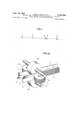
- FIG. 1 is an illustrative view of a flowsheet for the manufacture of the H-section steel by means of a universal roll mill.
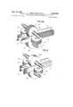
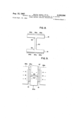
- FIG. 2(a) and (b) are illustrative views of embodiments of the present invention using a universal finishing roll mill.
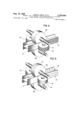
- FIG. 3 is an illustrative view of another embodiment of the present invention using a universal roll mill with a pair of plain horizontal rolls, and a pair of vertical rolls having notches over the entire rolling surface.
- FIG. 4 is an illustrative view of another embodiment of the present invention using a universal roll mill with a pair of plain horizontal rolls, one plain vertical roll and one vertical roll having notches over the entire rolling surface.
- FIG. 5 is an illustrative view of a universal rolling mill with one horizontal roll and one vertical roll which are plain, and one horizontal roll and one vertical roll each having notches on the center portion of the rolling surface.
- FIG. 6 is an illustrative view of another embodiment of the present invention using a universal roll mill with a pair of plain horizontal rolls, one flat vertical roll and one vertical roll having one or more kinds of notches on its rolling surface.
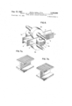
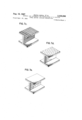
- FIG. 7(a), (b), (c), (d) and (e) are illustrative views of respective examples of steel H-sections rolled according to the present invention, having projections on the outer surface of flanges and/or on the surface of the web.
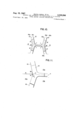
- FIG. 8 is an illustrative view of a steel H-section having projections of irregular height.
- FIG. 9 is an illustrative view showing the manner in which projections of irregular height are formed on the outer surface of flanges in rolling by means of a universal rolling mill.
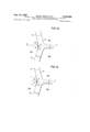
- FIG. 10 is an illustrative view, of the rolled state of a material formed by rough universal roll mill according to the process shown in FIG. 1.
- FIG. 11 is an illustrative view of flat vertical rolls shown in FIG. 10, mounted on a rough universal roll mill shown.
- FIG. 12 to FIG. 15 are illustrative views showing embodiments of the present invention using the vertical roll shown in FIG. 10 in a roughing universal roll mill.
- Steel H-sections having various projections on the flange surface and/or on the surface of the web manufactured according to the present invention, as mentioned above, is accompanied by the superior properties in addition to those of regular steel H-sections as a structural, piling, or temporarily used constructing material.
- the projections look very fine, having good adherence to concrete material, and when it is used'as piling it has high adherence to sand and mud.
- a steel H-section having striped projections is used as a pile it may be easily driven down vertically.
- a temporarily used constructing material for example as a trench cover 7 deck for covering a dug road in a subway construction, a steel H-section having projections on the outer surface of flanges is very useful, as will be mentioned later.
- the trench cover deck has been constructed by arranging many steel floor plates on a large number of auxiliary girders supported by main girders. And this steel floor plate has been a specially sized steel plate of l m. width, 2 in. length and 26) cm. thickness having a raised pattern on its surface, designed for car passage thereon.
- These conventional steel floor plates are so small, that they cannot be used again after being used as a road-covering, and require very expensive processing.
- said trench cover deck is so high, because it is constructed by three floors, namely large beams, small beams and steel floor plate, and requires deeper holes; hence higher cost of construction.
- the length is used, it may be used repeatedly for other purposes economically, for example, as constructing material other than the trench cover, structural material, or piling material, and simultaneously it has good adherence to concrete materials and sand and mud, and contributes substantially to a decrease in the construction cost.
- the steel H-section having projections on the outer surface of the flange according to the present invention may be used effectively as a steel bed plate for bridges and structures.
- the methods of manufacturing a steel H-section in a hot rolling mill may be classified as follows.
- the methods of (A), (C) and (D) are used to form projections on the outer surface of the flange and/or web or the method (B) is used to form projections on the web surface.
- a roughing roll mill with rolls having notches on their surface, or a finishing roll mill with rolls having notches on their surfaces is employed after rough rolling in the rolling line.
- the projection-forming roll mill with notched rolls may be used after ordinary finish rolling.
- a finishing roll mill and/or a flange edging roll mill may be used to finish the projections on the surface of the steel H-section or the form of the steel H-sections themselves.
- the methods of the present invention which are related to rolling methods (A), (C) and (D), above, are used for forming projections on the surfaces of steel H-sections, such as on the outer surface of one or both flanges and/ or on one or both web surfaces.
- These projections are formed by using a roughing roll mill or a finishing roll mill with a pair of vertical rolls, or a pair of upper and lower horizontal rolls, having suitable notches or recesses in the rolling surfaces of the rolls.
- the rolls may be used to form projections 0n the outer surface of only one flange or to form suitable projections on the outer surface of both flanges or on one or both surfaces of the Web. This is effected by using various combinations of plain and configured rolls.
- the roll mill can finish the H-section steel to accurate dimensions by onepass, and simultaneously can form suitable projection on the outer surfaces of the flanges and/or on the surface of the web, corresponding to the used rolls.
- Some kinds of projections may be formed by more than one rolling-pass.
- the configuration of projection, which is formed on the outer surface of flange and/or on the surface of the web, has no limitation as mentioned, but generally the height of projection is desirably less than 5 mm. and, when it is beyond 5 mm. limit, it is difficult to obtain the desired configuration.
- the desired configuration can be obtained more easily when the projections have a smaller inclination toward the flange surface, and the more round the projection-tip is, the more easily the desired configuration may be made; for example, a projection with half-round sectional area is more easy to roll than that with rectangular sectional area.
- the above points should be considered in rolling operations.
- the rolling temperature, the rolling speed, the rolling reduction, etc. they vary depending upon the grade, sectional area, wall thickness, configuration of projection, etc. of the material to be rolled.
- the rolling speed of the last pass in rough rolling for forming projections on the surface is within a range of 0.53.0 m./sec., and the reduction rate depends upon the wall thickness, height and configuration of the desired projection, and desirably within the range of 05-15 mm. generally.
- a roughing roll mill When a roughing roll mill is provided With flat rolls and a finishing roll mill is provided with notched rolls, in case of a killed steel, it is desirable to start rough rolling at 1130-980 C., and to start finish rolling at 960870 C. and finish at 940730 C. Also, in the case of a semi-killed steel or rimmed steel, it is desirable to finish roughing rolling at 1160990 C., to start finish rolling at 1050870 C. and finish at 1000-850 C.
- Conditions such as the rolling speed and reduction rate for the last pass of the finshing roll mill to form projections on the surface of a steel H-section is just the same as in the case of the roughing roll mill with notched rolls as above described.
- multiplepass reciprocating rolling can be performed.
- the above described conditions may be applied to any of the following cases of forming projections; forming them on the outer surface of the web, forming them on the surface of a flange, or forming them in combinations of these cases.
- FIGS. 1 and 2 One example of the present invention using a finishing rolling mill having notched rolls or universal rolling system is described with reference to FIGS. 1 and 2.
- FIG. 1 shows a rolling line for a steel H-section, wherein an ingot is rolled through a blooming mill 1, into required dimensions, subjected, if necessary, to a suitable heat treatment, and entered into No. 1 roughing roll mill (rough break down mill 2), and then passed through No. 2 roughing roll mill (rough universal mill 3). Then the material is rolled in all directions.
- the top portion of hte flange is rolled by a flange top rolling mill (edging mill 4), then by using a finishing roll mill having notched rolls on the rolling surfaces (finishing universal mill 5), the flange is rolled into a steel vertical position, and the material is formed into H-section with accurate form and dimensions.
- FIGS. 2a and 2b are detailed views of an important part 5 of FIG. 1, and particularly show a case of forming projections on the outer surface of both flanges (FIG. la) and a case of forming them on the outer surface of both flanges and on both web surfaces (FIG. 1b) using a finishing roll mill (finishing universal mill 5).
- Said fining roll mill 5 consists of one pair of upper and lower horizontal rolls 6 and one pair of vertical rolls 7 and, in the case of FIG.
- FIG. 2(1)) further shows a case of forming projections on the outer surface of both flanges of steel H-section (A) and on the both web surfaces, by means of similarly desired notches on the surface of upper and lower horizontal rolls.
- this invention relates to methods for forming projections of uniform height over the entire surface.
- Their features reside in that, in the manufacturing of steel H-sections having projections on the outer surface of flanges and/or on the web surface, when a material to be rolled has been brought in a rolling line, the rolling resistance of the flange portion is equalized by adjusting the temperature, or the amount of reduction in the web portion, or by adjusting both of them, and then rolling is effected using a steel H-section rolling mill provided with notched vertical rolls, or with both notched vertical rolls and notched horizontal rolls, and the metal of the flange portion enters into the notches of the rolling surface of the vertical rolls uniformly and fully.
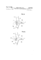
- projections 84 on the outer surface of the flange 81 of H-section steel as shown in FIG. 8 have such tendency that the projections 84a on the outer surface of the flange portion corresponding to the joining part 83 of the web 82 and the flange 81 have a lower height than the other projections 84b.
- the part of the flange which is located at the joining part of the web and the flange is at a higher temperature than the other parts of theflange.
- the joining part of the flange has a smaller material deforming-resistance than the other parts of the flange, and therefore when it is rolled by the vertical roll stand having notched rolls, its elongation in the rolling direction becomes larger.
- the flange in the joining part, has a smaller supporting force for the vertical rolls than the other parts of the flange, and consequently at the flange of the joining part, the amount of metal to enter into the notches on the rolling surface of the vertical rolls is smaller than at the other parts of flange.
- the temperature of the joining part is decreased by cooling the joining part or the flange of the joining part so that the temperature diflerence is decreased as much as possible, whereby the deformation resistance in all parts of the flange is made uniform, as well as the elongation of the flange in the rolling direction during the rolling by vertical rolls is made uniform.
- the hot-and-soft web which has small supporting force at the joining part, is cooled to decrease the temperature of the web near the joining part at least, and by increasing the deformation resistance of the web, the supporting force of the joining part is increased and the rolling resistance of the flange is equalized. Then the rolling is done to form projections on the outer surface of flanges, or on outer surface of flanges and on the surface of the web, as described in detail later.
- the temperature of the material to be rolled varies depending upon the grade, sectional size, thickness, etc., of the material, but generally it is not so desirable to decrease the temperature to about or less than 550 C.
- the cooling method for the joining part at the web and the flange and the web may be performed by natural cooling of the material to be rolled, or may be performed by using desirable coolants, for example, by jetting water, air or its mixture, etc. on the joining part and the web. Cooling of the web may be done by a cooled roll.
- Reduction for forming the flange or the web varies depending upon the thickness of material to be rolled, and the height and the shape of desired projections to be formed, but, in general, it may optionally be the same or more than the reduction of the finish-rolling of ordinary steel H-sections.
- the rolling speed it is suflicient to take the ordinary speed applied in the finishing rolling for steel H- sections and, if necessary, it is possible to use more or less speed optionally.
- the present invention relates to the rolling for forming projections of uniform height all over the outer surface of the flange when forming projections on the outer surface of flange or on the outer surface of the flange and the web surface, which will be described below, by adjusting the reduction in the web which has small supporting force for the joining part of the web and the flange.
- the joining part of the web and the flange of the material to be rolled is supported only by the hot-and-soft Web, as mentioned before, and therefore the joining part of the flange has a smaller supporting force for rolling of the vertical roll than the other flange which is supported by the side of the horizontal roll.
- the rolling pressure at the joining part of the web and the flange is the total sum of the pressures, applied by the horizontal and the vertical rolls.
- the whole pressure at the joining part is increased artificially by increasing the amount of reduction applied by horizontal rolls so that the decreased supporting force for vertical rolls due to the hot-and-soft web pressed by horizontal rolls, is reinforced, thus obtaining uniform rolling resistance on the whole area of the flanges, and projections are formed on the outer surface of the flange or on the outer surface of the flange and on the surface of web. In this way, rolling for forming projections of uniform height over the entire outer surface of the flange is performed.
- the amount of reduction in the web somewhat varies depending upon the sectional dimensions and wall thickness of the material to be rolled, but generally it is desirable to make the reduction about 1.2-10.0 times as large as the reduction in webs during finish rolling of ordinary steel H-sections; if it is under 1.2 times, the supporting force for the joining part of web and flange is not suflicient, and if it is over 10.0 times, the rolling of the steel H-section itself is not good and the consumption of notches on the rolling surface of the horizontal roll for forming projections on the web surface is increased. If reduction in the flange is not balanced with the increased reduction in the web, wavings on the web will be caused. In order to eliminate the threat of the wavings, a certain amount of reduction is taken so as to balance the elonga' tion of web with the elongation of flange.
- the rolling speed it can be taken as much as the rolling speed of finish rolling for ordinary H-section steel, or otherwise optionally, but care must be taken that, when the reduction is increased, loading current is increased correspondingly and simultaneously the load current is increased through forming projections. Therefore, it is necessary to limit the speed within the motor capacity and on the other hand the consumption of notches on the rolling surface of the roll is increased.
- FIG. 1 a material to be rolled by a projection-forming finishing universal roll mill 5, is rolled into rough shapes near to the finished product as shown in FIG. 10 with hatched line, by the group of roughing universal roll mills 3, 4.
- 13a, and 13b show upper and lower horizontal rolls of a roughing universal roll mill, 14a, and 14b, right and left vertical rolls and 14c and 14d, peripheral surfaces of the vertical rolls 14a, 1411.
- the material A is rolled to required web-thickness, flange-thickness and flange-height by several or more reversing passes and is sent to the projection-forming finishing universal roll mill of FIG. 1, or FIG. 9, FIG. 2, and herein is finished and simultaneously projections are formed on the outer surface of the flange.
- the projection-forming finishing universal roll mill of FIG. 1, or FIG. 9, FIG. 2 is sent to the projection-forming finishing universal roll mill of FIG. 1, or FIG. 9, FIG. 2, and herein is finished and simultaneously projections are formed on the outer surface of the flange.
- the pressure by the vertical rolls 6a, 6b is not so sufiicient on part (B) as on part (A), so that at the part (B) the material does not fill up completely notches which are provided on the surface of the vertical rolls 6a, 6b.
- the object of the present invention is to prevent irregularity in the height and configuration of the projections which are formed on the outer surface of the flanges of a steel H-section produced according to the abovementioned universal rolling system, and to provide methods of forming projections of uniform form and configuration over the entire outer surface of flanges of the steel H-section.
- the features reside in that, through suitable variation of the patterns on the rolling surfaces of vertical rolls in a roughing universal roll mill, the thickness of the outer surface of the joining part of the web and the flange of the material to be supplied to the projection-forming finishing universal roll mill is increased and, by increasing the reduction in the outer surface of the joining part of the web and the flange in the projection-forming finishing roll mill, projections of uniform height and configuration are formed over the entire outer surface of the flange.
- the selection for the form of vertical rolls for the purpose of increasing the thickness of the joining part of the web and the flange of the material to be rolled may be made according to the dimensions of the steel H-sction, having projections on the outer surface of the flanges, to be manufactured; the web thickness, the flange thickness, the web height and the flange width etc.
- FIG. 11 shows the form of the vertical rolls for an ordinary steel H-shape in the roughing universal roll mill as shown in FIG. 10, used in a rolling mill train for a steel H-section having projections on the outer surface of the flange as shown in FIG. 1.
- FIG. 12 to FIG. 15 show some examples of the vertical rolls according to the present invention in similar way as FIG. 10. Most of the vertical rolls 14a, 14b in the roughing universal roll mill, as shown in FIG.
- the profile of the rolling surface is made by the upper and lower lines 15 and 16 and the are which is formed by the radius (R), so that a space is made between the rolling surface and the intersection point 17 of the upper and lower lines 15 and 16 and the distance from the rolling surface to the intersection point 17 along the center line (n) of the web is referred to as (I).
- FIGS. 12 to 15 examples of the form of the vertical roll of a roughing universal rolling mill used in the present invention for increasing the thickness of the outside surface of the joining part of the web and the flange of a material to be rolled are shown in FIGS. 12 to 15.
- FIG. 12 shows the profile of the rolling surface in a similar way as FIG. 11.
- the radius (R) is longer than that of FIG. 11, and the distance (I) is longer.
- FIG. 13 the profile of the rolling surface is made by the upper and lower lines 15 and 16 and the perpendicular line 18 intersecting the point (/11) on the center line (n) of the web.
- the distance (I) is longer than that of FIG. 11 and the radius (r) may be of any suitable length.
- FIG. 12 shows the profile of the rolling surface in a similar way as FIG. 11.
- the radius (R) is longer than that of FIG. 11, and the distance (I) is longer.
- the profile of the rolling surface is made by the upper and lower lines 15 and 16 and the perpendic
- the profile of the rolling surface is made by the upper and lower lines 15 and 16, an are 19 drawn by the radius (R) having its center on the center line of the web, intersecting the point (m), and arcs 2'1 and 21 drawn by the radius (r) of 1% appropriate length.
- the distance (I) is longer than that of FIG. 11.
- the profile of the rolling surface is made by an are 20 of the radius (R) of enough length intersecting the point (m) and having its center on the center line (12) of the web, and the lines 15 and 16.
- (r) is a radius of appropriate length, and the distance (l) is longer than that of FIG. 11.
- the thickness of the outside surface of the joining part of the web and the flange of a material to be supplied to the projection-forming finishing universal roll mill is increased by the roughing universal roll mill provided with such vertical rolls, and as for the increase in the thickness, it is, as mentioned above, enough to make the reduction uniform over the entire flange or to make the reduction in the joining part of the web and the flange a little larger than that in other parts.
- the rolling conditions applicable in the present invention such as the material temperature, the reduction and the rolling speed at rolling for projection-forming, the rolling conditions for the ordinary steel H-section can be applied.
- the apparatus according to the invention relates to the universal rolling mill for effectively and easily manufacturing the H-section steel having desirable projections on the outsides of the flange and/or the surfaces of the web and which has excellent characteristics as mentioned above.
- the feature of the apparatus resides in that it is a universal rolling mill provided with rolls having notches in rolling surface.
- the methods of manufacturing a steel H-section in hotrolling are generally classified as under.
- the apparatus of the present invention uses such a universal rolling mill as permits the use of a powerful vertical roll for the production of a steel H-section having desirable projections on the surfaces thereof, namely on the outer surface of the flange and/or on the web surface, :as described above, wherein notches are provided on the rolling surfaces of a pair of horizontal rolls or a pair of vertical rolls so that enough pressure can be applied on the outer surface of the flange and thus projections of enough height can be formed on the outer surface of the flange as well as on the web surface.
- This is the important feature in using the universal rolling mill in the apparatus of the present invention.
- notches and their combinations are selected adequately corresponding to the individual applications of the H-section steel having projections on the surface to be manufactured, as mentioned before.
- rolls having notches on the rolling surface are provided in a universal rolling mill as one pair of the upper and lower horizontal rolls and/ or one pair of vertical rolls depending on the individual application of the steel H-section having projections on the surface to to be manufactured so that the required projections are suitably formed on the surface of the flange and/or on the web surface.
- the universal rolling mill for manufacturing the steel I-I-section having projections on said surface according to the invention is used always after rough rolling as in a roughing roll mill or finishing roll mill on the rolling line in the process of steel H-section manufacturing, but generally, according to this invention it is desirable to use in combination the roughing roll mill with flat rolls and the surface projected steel H-section manufacturing universal roll mill.
- the universal rolling mill of this invention may be used after the ordinary finish rolling.
- finishing roll mill or a flangeedging mill for finishing the configuration of projections on the surface of a steel H-section or the form of the steel H-section itself, which has been rolled by the universal roll mill of the invention.
- Example 1 A steel H-section having many spaced longitudinal projections of little rounded trapezoid cross section of 3 m./m. height and 5 m./m. width with m./m. pitches on the outer surfaces of the both flanges and the both surfaces of the web, shown in FIG. 7(a) was obtained by applying one rolling pass on the steel H-section through a finishing mill (finishing universal mill) having vertical notches on the vertical roll and the horizontal roll in the finishing step in the rolling line.
- finishing mill finishing universal mill
- Example 2 A steel H-section having many spaced traverse projections of little rounded trapezoid cross section of 2.5 m./m. height, and 4 mm. width with 15 mm. pitches on the outer surface of the both flanges, as shown in FIG. 7(b), was obtained by applying one rolling pass on the steel H-section through a finishing mill (finishing universal mill) having notches of inversed trapezoid cross section on the vertical roll, after the roughing rolling in the rolling line.
- finishing mill finishing universal mill
- Example 3 A steel H-section having many hemispherically projections of 10 mm. diameter on the outside surface of the flange at one side as shown in FIG. 7(d) was obtained by applying one rolling pass on the steel H-section through a finishing mill (finishing universal mill) having hemispherical notches on the vertical roll, after roughing rolling in the rolling line.
- finishing mill finishing universal mill
- Example 4 A steel H-section having many spaced projections of little rounded trapezoid cross section of 2 mm. height and 10 mm. width with 10 mm. pitches on the surfaces of the web and many spaced projections of little rounded trapezoid cross section of 4 mm. height and 12 mm. width with 12 mm. pitches on the outer surfaces of the both flanges, as shown in FIG. 7(0) was obtained by applying one rolling pass on the H-section steel through a finishing mill (finishing universal mill) having longitudinal grooved notches of inverted trapezoid cross section on the horizontal rolls and lateral grooved notches of inverted trapezoid cross section on the vertical rolls, after roughing rolling in the rolling line.
- finishing mill finishing universal mill
- Example 5 In forming hemispherical projections over the entire outer surface of both flanges of a steel H-section (semikilled steel) of 192x197 W/F /s, a material to be rolled 'was cooled naturally so as to minimize the temperature difference of the flanges and the temperature of the material was maintained about 720 C. in a process of rough rolling in a rolling line. The material was similarly treated before finish rolling in the rolling line. The material was passed one time with a reduction of 0.4 m./m. by the horizontal rolls and a reduction of 1.5% by the vertical rolls at a rolling speed of 1.3 m./sec. through a finish universal roll mill having hemispherical notches of 4 mm. depth over the entire rolling surfaces of one pair of vertical rolls, and hemispherical projections of about 1.2 mm. height were formed over the entire outer surfaces of both flanges. The height of the projections was uniform in this case.
- the material was given one rolling pass with a reduction of 0.4 mm. by the horizontal rolls and a reduction of 3.8 mm. by the vertical rolls at a rolling speed of 3.2 m./sec.
- Example 7 In forming many longitudinal projections of trapezoid cross section over the entire outer surface of a flange at one side of a steel H-section of 300x300 W/F: after rough rolling in the rolling line, Water was jetted all over the web to forcibly cool the material so that the temperature of the material was maintained about 700 C. Then the material was given one rolling pass with a reduction of 0.8 mm. by the horizontal rolls and a reduction of 3.8 mm. by the vertical rolls at a rolling speed of 3 m./sec. through a finishing universal rolling mill having notches of inverted trapezoid cross section of 5 mm.
- Example 11 A steel H-section (A) having projections 13 in the form of longitudinal ribs over the entire outer surface of one flange with smooth surfaces of the web and a smooth surface of the other flange was manufactured by a universal roll mill as shown in FIG. 4, provided with one vertical roll 7b having grooves 12 circumferentially around the entire rolling surface, and a pair of plain horizontal rolls 6 and one plain vertical roll 7.
- FIG. 6 shows one example of a universal rolling mill according to the present invention, wherein the pair of horizontal rolls 6a and 6b and one of the vertical rolls 7a are plain rolls, and the other of the vertical rolls 7b is a roll having more than one kind of notches (C) or patterns all over its rolling surface.
- Steel H-section (A) is rolled by the above rolling mill to obtain a steel H- section having one smooth outer flange surface and two smooth web surfaces, and having more than one kind of projections (E) over the entire other outer flange surface, and more than one kind of projections were formed by one rotation of the roll.
- the adherence for sand and mud is also good, and when steel H-section having longitudinal projections on the outer surface of the flanges and/or on the surface of the web is so used, it is very advantageous because the pile can be driven perpendicularly.
- the steel H-section having projections on the outer surface of the flange can be advantageously used.
- a steel H-section having projections on the outer surface of the flanges is very effective as compared with other road-covering materials, and the outer surface can be used as a road surface. Therefore, the steel H-section according to the present invention is very advantageous in many points.
- a method of manufacturing a steel H-section including a pair of flanges interconnected by a web and having projections on the outer surface of at least one flange, the projections being uniform in height and configuration, said method comprising the steps of: rough rolling a steel ingot to produce an H-cross section beam including a pair of flanges interconnected by a web at junctures between the web and the flanges; during the rough rolling, subjecting the web to treatment to increase its resistance to deformation under pressure applied to the outer surfaces of the flanges; and finish rolling the rough-rolled H-beam using rolls pressing against the outer surfaces of the flanges and at least one having a rolling surface recessed to form said projections; the increased resistance to deformation of the web assuring those projections adjacent a juncture of the web with the flanges being uniform in height and configuration with the remainder of the projections formed on the same surface.
- a method of manufacturing a steel H-section including a pair of flanges interconnected by a web and having projections on the outer surface of at least one flange, the projections being uniform in height and configuration comprising the steps of: rough rolling a steel ingot to produce an H-cross section beam including a pair of flanges interconnected by a web at junctures between the web and the flanges; during the rough rolling, increasing the wall thickness of the metal on the outer surfaces of the flanges at said junctures by using flange forming rough rolls contoured to provide such increase in wall thickness, to increase the resistance of the web to deformation under pressure applied to the outer surfaces of the flanges; and finish rolling the rough-rolled H-beam using rolls pressing against the outer surfaces of the flanges and at least one having a rolling surface recessed to form said projections; the increased resistance to deformation of the web assuring those projections adjacent a juncture of the web with the flanges being uniform in height and configuration
- a method of manufacturing a steel H-section including a pair of flanges interconnected by a web and having projections on the outer surface of at least one flange, the projections being uniform in height and configuration comprising the steps of: rolling a steel ingot to produce an H-cross section beam including a pair of flanges interconnected by a web at junctures between the web and the flanges, and using rolls pressing against the outer surfaces of the flanges and at least one having a rolling surface recessed to form said projections; and during the rolling selectively cooling the metal in a manner to increase the resistance of the web deformation under the pressure applied to the outer surfaces of the flanges; the increased resistance to deformation of the web assuring those projections a juncture of the web with the flanges being uniform in height and configuration with the remainder of the projections formed on the same surface.
- a method of manufacturing a steel H-section including a pair of flanges interconnected by a web and having projections on the outer surface of at least one flange, the projections being uniform in height and configuration, said method comprising the steps of rolling a steel ingot to produce an H-cross section beam including a pair of flanges interconnected by a web at junctures between the web and the flanges, and using rolls pressing against the outer surfaces of the flanges and at least one having a rolling surface recessed to form said projections; during the rolling, subjecting the web and the flanges to selective reduction to increase the resistance of the web to deformation by an amount to insure a uniform resistance to deformation throughout the areas of the flanges; the increased resistance to deformation of the web assuring the projections adjacent a juncture of the Web with the flanges being uniform in height and configuration with the remainder of the projections formed on the same surface.
Landscapes
- Engineering & Computer Science (AREA)
- Mechanical Engineering (AREA)
- Metal Rolling (AREA)
- Reduction Rolling/Reduction Stand/Operation Of Reduction Machine (AREA)
Applications Claiming Priority (5)
| Application Number | Priority Date | Filing Date | Title |
|---|---|---|---|
| JP5307163 | 1963-10-01 | ||
| JP8366863 | 1963-11-05 | ||
| JP5984363 | 1963-11-05 | ||
| JP8366863 | 1963-11-05 | ||
| JP895464 | 1964-02-19 |
Publications (1)
| Publication Number | Publication Date |
|---|---|
| US3335596A true US3335596A (en) | 1967-08-15 |
Family
ID=27519005
Family Applications (1)
| Application Number | Title | Priority Date | Filing Date |
|---|---|---|---|
| US399300A Expired - Lifetime US3335596A (en) | 1963-10-01 | 1964-09-25 | Methods and apparatus for manufacture of h-section steel having surface projections |
Country Status (6)
| Country | Link |
|---|---|
| US (1) | US3335596A (fr) |
| BE (1) | BE653689A (fr) |
| DE (1) | DE1427880A1 (fr) |
| FR (1) | FR1425307A (fr) |
| GB (1) | GB1087551A (fr) |
| LU (1) | LU47040A1 (fr) |
Cited By (11)
| Publication number | Priority date | Publication date | Assignee | Title |
|---|---|---|---|---|
| US3538732A (en) * | 1966-06-21 | 1970-11-10 | Nippon Steel Corp | Method and apparatus for producing channel steels |
| US4106551A (en) * | 1976-05-18 | 1978-08-15 | Concast Ag | Roller assembly in the guide path of a continuous casting machine for beam blanks |
| US4367642A (en) * | 1978-09-12 | 1983-01-11 | Kawasaki Steel Corporation | Method of producing H-beams |
| US5823042A (en) * | 1997-03-14 | 1998-10-20 | J&L Structural, Inc. | Method of making an improved hot rolled I-beam and associated product |
| US6219990B1 (en) | 1998-04-07 | 2001-04-24 | J&L Structural, Inc. | Method of making an improved hot rolled I-beam and associated product |
| US20060110220A1 (en) * | 2004-11-19 | 2006-05-25 | Edward Cable | Irregularly surfaced h pile |
| US20140124721A1 (en) * | 2011-06-22 | 2014-05-08 | Ashley Dean Olsson | Post-forming method and apparatus |
| US9279228B1 (en) | 2013-03-14 | 2016-03-08 | Hercules Machinery Corporation | Pull-out resistant piles |
| US20180117651A1 (en) * | 2015-04-27 | 2018-05-03 | Mitsubishi Heavy Industries, Ltd. | Milling apparatus |
| US11028573B1 (en) * | 2020-01-16 | 2021-06-08 | Novel Structures, LLC | Serrated beam |
| US11725386B2 (en) * | 2020-01-16 | 2023-08-15 | Simpson Strong-Tie Company Inc. | Serrated beam |
Families Citing this family (1)
| Publication number | Priority date | Publication date | Assignee | Title |
|---|---|---|---|---|
| GB2510609B (en) * | 2013-02-08 | 2015-12-09 | Primetals Technologies Ltd | Method of manufacturing a beam |
Citations (9)
| Publication number | Priority date | Publication date | Assignee | Title |
|---|---|---|---|---|
| US1812248A (en) * | 1928-12-29 | 1931-06-30 | William C Oberg | Roll |
| US1812246A (en) * | 1928-12-27 | 1931-06-30 | William C Oberg | Method of making flanged shapes |
| US1856898A (en) * | 1928-03-30 | 1932-05-03 | Alan D Wood | Fabrication of embossed metallic plates |
| US1882956A (en) * | 1929-08-22 | 1932-10-18 | Johnson Bronze Co | Bearing |
| US2047001A (en) * | 1932-12-10 | 1936-07-07 | Preston Davie | Apparatus for making foraminous elements |
| US2277725A (en) * | 1939-07-04 | 1942-03-31 | Richard S Smith | Decorating metallic surfaces |
| US2782487A (en) * | 1950-05-12 | 1957-02-26 | Properzi Ilario | Device for making metal pellets, particularly for shotguns |
| US3165948A (en) * | 1960-07-23 | 1965-01-19 | Yawata Iron & Steel Co | Method of rolling h-sectioned steel members and mill train for the same |
| US3251213A (en) * | 1961-11-22 | 1966-05-17 | Fuji Iron & Steel Company Ltd | Method of manufacturing h-beams |
-
1964
- 1964-09-25 US US399300A patent/US3335596A/en not_active Expired - Lifetime
- 1964-09-29 BE BE653689D patent/BE653689A/xx unknown
- 1964-09-29 LU LU47040D patent/LU47040A1/xx unknown
- 1964-09-30 DE DE19641427880 patent/DE1427880A1/de active Pending
- 1964-09-30 FR FR989943A patent/FR1425307A/fr not_active Expired
- 1964-10-01 GB GB40041/64A patent/GB1087551A/en not_active Expired
Patent Citations (9)
| Publication number | Priority date | Publication date | Assignee | Title |
|---|---|---|---|---|
| US1856898A (en) * | 1928-03-30 | 1932-05-03 | Alan D Wood | Fabrication of embossed metallic plates |
| US1812246A (en) * | 1928-12-27 | 1931-06-30 | William C Oberg | Method of making flanged shapes |
| US1812248A (en) * | 1928-12-29 | 1931-06-30 | William C Oberg | Roll |
| US1882956A (en) * | 1929-08-22 | 1932-10-18 | Johnson Bronze Co | Bearing |
| US2047001A (en) * | 1932-12-10 | 1936-07-07 | Preston Davie | Apparatus for making foraminous elements |
| US2277725A (en) * | 1939-07-04 | 1942-03-31 | Richard S Smith | Decorating metallic surfaces |
| US2782487A (en) * | 1950-05-12 | 1957-02-26 | Properzi Ilario | Device for making metal pellets, particularly for shotguns |
| US3165948A (en) * | 1960-07-23 | 1965-01-19 | Yawata Iron & Steel Co | Method of rolling h-sectioned steel members and mill train for the same |
| US3251213A (en) * | 1961-11-22 | 1966-05-17 | Fuji Iron & Steel Company Ltd | Method of manufacturing h-beams |
Cited By (15)
| Publication number | Priority date | Publication date | Assignee | Title |
|---|---|---|---|---|
| US3538732A (en) * | 1966-06-21 | 1970-11-10 | Nippon Steel Corp | Method and apparatus for producing channel steels |
| US4106551A (en) * | 1976-05-18 | 1978-08-15 | Concast Ag | Roller assembly in the guide path of a continuous casting machine for beam blanks |
| US4367642A (en) * | 1978-09-12 | 1983-01-11 | Kawasaki Steel Corporation | Method of producing H-beams |
| US5823042A (en) * | 1997-03-14 | 1998-10-20 | J&L Structural, Inc. | Method of making an improved hot rolled I-beam and associated product |
| US6219990B1 (en) | 1998-04-07 | 2001-04-24 | J&L Structural, Inc. | Method of making an improved hot rolled I-beam and associated product |
| US7556454B2 (en) * | 2004-11-19 | 2009-07-07 | Nucor Yamato Steel Company | Irregularly surfaced H pile |
| US20060110220A1 (en) * | 2004-11-19 | 2006-05-25 | Edward Cable | Irregularly surfaced h pile |
| US20090311051A1 (en) * | 2004-11-19 | 2009-12-17 | Nucor Yamato Steel Company | Irregularly surfaced h pile |
| US20140124721A1 (en) * | 2011-06-22 | 2014-05-08 | Ashley Dean Olsson | Post-forming method and apparatus |
| US9662694B2 (en) * | 2011-06-22 | 2017-05-30 | Ashley Dean Olsson | Post-forming method and apparatus |
| US9279228B1 (en) | 2013-03-14 | 2016-03-08 | Hercules Machinery Corporation | Pull-out resistant piles |
| US20180117651A1 (en) * | 2015-04-27 | 2018-05-03 | Mitsubishi Heavy Industries, Ltd. | Milling apparatus |
| US10940515B2 (en) * | 2015-04-27 | 2021-03-09 | Mitsubishi Heavy Industries, Ltd. | Milling apparatus |
| US11028573B1 (en) * | 2020-01-16 | 2021-06-08 | Novel Structures, LLC | Serrated beam |
| US11725386B2 (en) * | 2020-01-16 | 2023-08-15 | Simpson Strong-Tie Company Inc. | Serrated beam |
Also Published As
| Publication number | Publication date |
|---|---|
| BE653689A (fr) | 1965-01-18 |
| GB1087551A (en) | 1967-10-18 |
| FR1425307A (fr) | 1966-01-24 |
| DE1427880A1 (de) | 1970-02-26 |
| LU47040A1 (fr) | 1964-11-30 |
Similar Documents
| Publication | Publication Date | Title |
|---|---|---|
| US3707088A (en) | Forming hollow ribs in metal sheet | |
| JPH0342122B2 (fr) | ||
| DE1427880A1 (de) | Verfahren zur Herstellung von H-Traegern mit Vorspruengen auf der Aussenflaeche mindestens eines Flansches | |
| US4637241A (en) | Fully universal rolling process for H or I-beam type metal sections | |
| US3251213A (en) | Method of manufacturing h-beams | |
| GB2071188A (en) | Steel H-sheet pile and producing method thereof | |
| US1623273A (en) | Process of rolling flanged beams | |
| US3425254A (en) | Rolling of slabs | |
| CN108176713A (zh) | 一种热轧花纹h型钢、轧制方法和轧制设备 | |
| JP2826044B2 (ja) | フランジを有する形材の圧延方法および圧延装置列 | |
| JP3840838B2 (ja) | 圧延h形鋼およびその製造方法 | |
| US3488986A (en) | Method of roughing structural great-width beams | |
| JPH07124602A (ja) | Z型鋼矢板用粗形鋼片の圧延方法 | |
| US1757388A (en) | Rolled-metal beam | |
| US3570293A (en) | Building construction | |
| JPS602921B2 (ja) | 突起付き形鋼の製造方法 | |
| US1623272A (en) | Manufacture of flanged beams with thin webs | |
| JPH07178402A (ja) | 鋼製連壁用形鋼の製造方法 | |
| JP2720750B2 (ja) | H形鋼の圧延機列 | |
| JP2577660B2 (ja) | 溝形鋼の熱間圧延方法 | |
| US1623271A (en) | Manufacture of flanged beams | |
| JP2861831B2 (ja) | 外法一定平行フランジ溝形鋼の圧延方法 | |
| JPH026001A (ja) | 形鋼の圧延方法 | |
| JPH0332408A (ja) | フランジ内面突起付h形鋼及びその仕上圧延装置 | |
| JPH05329521A (ja) | H形鋼圧延方法 |