US3603254A - Method and apparatus for sequentially moving dampening rollers - Google Patents
Method and apparatus for sequentially moving dampening rollers Download PDFInfo
- Publication number
- US3603254A US3603254A US738268A US3603254DA US3603254A US 3603254 A US3603254 A US 3603254A US 738268 A US738268 A US 738268A US 3603254D A US3603254D A US 3603254DA US 3603254 A US3603254 A US 3603254A
- Authority
- US
- United States
- Prior art keywords
- roller
- plate cylinder
- dampening fluid
- rollers
- fountain
- Prior art date
- Legal status (The legal status is an assumption and is not a legal conclusion. Google has not performed a legal analysis and makes no representation as to the accuracy of the status listed.)
- Expired - Lifetime
Links
- 238000000034 method Methods 0.000 title claims description 12
- 239000012530 fluid Substances 0.000 claims abstract description 130
- 238000007639 printing Methods 0.000 claims description 28
- 230000007246 mechanism Effects 0.000 abstract description 3
- 239000000543 intermediate Substances 0.000 description 112
- 239000004744 fabric Substances 0.000 description 4
- 238000010276 construction Methods 0.000 description 2
- XLYOFNOQVPJJNP-UHFFFAOYSA-N water Substances O XLYOFNOQVPJJNP-UHFFFAOYSA-N 0.000 description 2
- 101100058891 Mus musculus Ca10 gene Proteins 0.000 description 1
- 230000009471 action Effects 0.000 description 1
- 239000000654 additive Substances 0.000 description 1
- 239000011248 coating agent Substances 0.000 description 1
- 238000000576 coating method Methods 0.000 description 1
- 230000007423 decrease Effects 0.000 description 1
- 230000007547 defect Effects 0.000 description 1
- 230000001419 dependent effect Effects 0.000 description 1
- 238000006073 displacement reaction Methods 0.000 description 1
- 238000004945 emulsification Methods 0.000 description 1
- 235000015250 liver sausages Nutrition 0.000 description 1
- 238000007645 offset printing Methods 0.000 description 1
- XYSQXZCMOLNHOI-UHFFFAOYSA-N s-[2-[[4-(acetylsulfamoyl)phenyl]carbamoyl]phenyl] 5-pyridin-1-ium-1-ylpentanethioate;bromide Chemical compound [Br-].C1=CC(S(=O)(=O)NC(=O)C)=CC=C1NC(=O)C1=CC=CC=C1SC(=O)CCCC[N+]1=CC=CC=C1 XYSQXZCMOLNHOI-UHFFFAOYSA-N 0.000 description 1
- 230000007480 spreading Effects 0.000 description 1
- 238000009736 wetting Methods 0.000 description 1
Images


Classifications
-
- B—PERFORMING OPERATIONS; TRANSPORTING
- B41—PRINTING; LINING MACHINES; TYPEWRITERS; STAMPS
- B41F—PRINTING MACHINES OR PRESSES
- B41F7/00—Rotary lithographic machines
- B41F7/20—Details
- B41F7/24—Damping devices
- B41F7/40—Devices for tripping or lifting damping rollers; Supporting, adjusting, or removing arrangements therefor
Definitions
- a dampener unit that transfers dampening fluid from a fountain to the surface of a plate cylinder.
- the dampener unit includes a fountain roller, a metering roller, an intermediate roller and one or more form rollers.
- the rollers are in series contact and the form rollers transfer the dampening fluid to the surface of the plate cylinder.
- Cam actuated form roller positioning devices are arranged to sequentially move the form roller away from the surface of the plate cylinder and thereafter move the form rollers aivay from and out of surface contact with the intermediate roller.
- a crank arm connected to the same actuator as the cam is connected to a lever mechanism that moves the metering roller away from the fountain roller.
- the rollers are repositioned in operative dampening fluid transfer position by first moving the metering roller into surface contact with the fountain roller. After the intermediate roller is into surface contact with the inter mediate roller. After the form rollers are wetted with dampening fluid, the form rollers are moved into surface contact with the plate cylinder and dampening fluid is transferred from the fountain to the surface of the plate cylinder without ink pickup by the rollers of the dampening unit from the plate cylinder.
- Suitable drive gearing is associated with the cylinders of the dampening unit to rotate the cylinders at preselected speeds relative to each other.
- dampening fluid normally water with or without additives
- the dampening unit includes a plurality of rollers in series contact between the source of fluid and the plate cylinder. If the form rollers are not wetted sufficiently with dampening fluid, ink from the plate cylinder will be transferred from the plate cylinder to the other rollers of the dampening unit. Ink on the rollers decreases substantially the efficiency of the dampener unit and the quality of the printed sheet.
- the amount of dampening fluid transferred to the plate cylinder should be carefully metered and uniformly applied.
- the amount of dampening fluid transferred to the plate cylinder should be maintained at a minimum and theoretically only enough dampening fluid transferred to form a uniform minimum thickness film on the nonprinting area of the plate to repel the ink.
- an excessive amount of dampening fluid should be transferred. Rather than improving the printing operation, the use of excessive fluid multiplied the problems and reduced the printing quality proportionately.
- a proposed solution to this problem is to use a specially treated transfer roller that has a hydrophillic roller surface.
- the film of dampening fluid on the roller surface is transferred to the plate cylinder by surface contact with an ink form roller.
- the film of dampening fluid is split so that a portion is picked up by the ink on the ink form roller and transferred to the plate cylinder. The other portion remains as a film on the hydrophillic transfer roller.
- the transfer of dampening fluid is dependent on a film of ink on an ink form roller.
- the above disclosed arrangement requires specially treated rollers to make the entire surface of the roller hydrophillic.
- the dampening unit includes a fountain roller partially immersed in a reservoir of dampening fluid.
- a metering roller is in surface contact with the fountain roller and an intermediate roller to transfer a controlled amount of dampening fluid from the fountain roller to the intermediate roller.
- Two or more form rollers are in surface contact with the intermediate roller and the surface of the plate cylinder.
- the form rollers are operable to transfer a film of dampening fluid from the intermediate roller to the surface of the plate cylinder.
- Form roller positioning means are provided to move the form rollers into and out of contact with the surface of the plate cylinder and into and out of contact with the surface of the intermediate roller.
- metering roller positioning means operable to move the metering roller toward and away from said fountain roller.
- the form rollers may be sequentially moved first out of contact with the plate cylinder while the form rollers are wetted by dampening fluid, and thereafter moved out of contact with the intermediate roller to thus eliminate ink pickup from the plate cylinder.
- the metering roller is thereafter moved out of contact with the fountain roller.
- the metering roller is first moved into surface contact with the fountain roller and after the intermediate roller is wetted with dampening fluid, the form rollers are thereafter moved into surface contact with the intermediate roller to wet the surface of the form rollers with dampening fluid. After the surfaces of the form rollers are wetted with dampening fluid, they are moved into surface contact with the plate cylinder to transfer dampening fluid from the reservoir to the surface of the plate cylinder.
- Another object of this invention is to provide a dampening unit wherein the form rollers are arranged to first move out of surface contact with the plate cylinder and thereafter out of surface contact with an intermediate roller to eliminate ink pickup on the rollers from the plate cylinder.
- a further object of this invention is to provide a dampening unit wherein the form rollers are spaced from an intermediate roller and from the surface of a plate cylinder and are arranged to first move into surface contact with the intermediate roller and, after the surface of the form rollers is wetted with the dampening fluid, into surface contact with the plate cylinder.
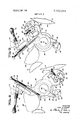
- FIG. 1 is a view in side elevation of the dampening unit illustrating the form roller positioning means and the metering roller positioning means.
- FIGS. 2, 3, 4 and 5 are diagrammatic representations of the dampening unit of FIG. 1 illustrating sequentially the relative positions of the form rollers and the metering roller as the dampening unit is disengaged from the printing cylinder.
- FIGS. 20, 3a, 4a and 5a are diagrammatic representations of the positioning cam for the fonn rollers with the cam rollers positioned on segments of the cam to maintain the position of the form rollers as illustrated in corresponding FIGS. 2-5 inelusive.
- FIGS. 2b, 3b, 4b and 5b are diagrammatic illustrations of the metering roller positioning device in the position to maintain the metering roller in the positions illustrated in corresponding FIGS. 2-5 inclusive.
- FIG. 6 is similar to FIG. 1 and illustrates the form roller positioning means in a position with the form rollers spaced from the plate cylinder and in surface contact with the intermediate cylinder, as shown diagrammatically in FIG. 3.
- FIG. 7 is a view similar to FIG. 6 illustrating the form rollers spaced from the plate cylinder and the intermediate roller similar to the positions diagrammatically illustrated in FIGS. 4
- FIG. 8 is a view in side elevation of the form roller positioning device for the lower form roller.
- FIG. 9 is a view in side elevation of the form roller positioning device for the upper form roller.
- a metering roller 20 is arranged to be in surface contact with the fountain roller 16 and receive dampening fluid from the surface of the fountain roller and transfer this dampening fluid to an intermediate roller 22 which may be a vibrator roller.
- the surface of the intermediate roller 22 is treated to be water receptive in the usual manner and preferably reciprocates axially to provide a transverse spreading action of the dampening fluid.
- the intermediate roller 22 is in surface contact with the form rollers 24 and 26 in a manner that the surfaces of the form rollers 24 and 26 are wetted with the dampening fluid.
- the form rollers 24 and 26 are in turn positioned in surface contact with the surface 12 of plate cylinder 14.
- Suitable drive means such as gearing and the like is provided to rotate the respective rollers and plate cylinders at preselected relative speeds to transfer the dampening fluid from the reservoir 18 to the surface 12 of plate cylinder 14 in the direction indicated in FIGS. 2-5 inclusive.
- the metering roller 20 remains in surface contact with the intermediate roller 22 both during the transfer of dampening fluid to the impression cylinder 14 and when the transfer of metering fluid is interrupted by movement of the other rollers out of surface contact with each other. With this arrangement, during the transfer of dampening fluid from the fountain roller 16, a continuous metered film of dampening fluid is transferred from the metering roller 20 to the intermediate roller 22.
- FIG. 2 illustrates the on" impression position or, stated otherwise, the position of the respective rollers when the dampening fluid is being transferred from the reservoir 18 to the surface of the plate cylinder 14.
- Fountain roller 16 is in surface contact with metering roller 20 and intermediate roller 22 is, in turn, in surface contact with metering roller 20.
- dampening fluid is transferred from the fountain roller 16 to metering roller 20 and then to intermediate roller 22.
- the form rollers 24 and 26 are in surface contact with both the intermediate roller 22 and the surface 12 of plate cylinder 14. Dampening fluid from intermediate roller 22 is thus transferred to the form rollers 24 and 26 and from form rollers 24 and 26 to the surface 12 of plate cylinder 14.
- the first movement of the form rollers 24 and 26 is illustrated in FIG. 3.
- the form rollers 24 and 26 rotate in a circular are about the axis of the intermediate roller 22 away from or out of contact with surface 12 of plate cylinder 14. It should be noted, however, that the form rollers 24 and 26 remain. in surface contact with the intermediate roller 22 so that the surfaces of form rollers 24 and 26 will continue to be wetted with dampening fluid from the intermediate roller 22.
- This arrangement provides for continued wetting of the form rollers 24 and 26 and prevents the transfer of ink to the form rollers 24 and 26 from the plate cylinder 14 and transfer of ink to the intermediate roller 22 should the form rollers 24 and 26 have ink thereon.
- FIG. 4 The next sequential movement of the respective rollers is illustrated in FIG. 4 where the form rollers 24 and 26 are moved in an are other than the circular arc about the axis of the intermediate roller 22 so that the form rollers 24 and 26 are moved out of surface contact with the intermediate roller 22.
- the metering roller 20 remains in surface contact with the fountain roller and with the intermediate roller 22 to continue to transfer dampening fluid thereto.
- the form rollers 24 and 26 while wetted with dampening fluid are moved away from the intermediate roller to prevent the transfer of ink from the form rollers to the intermediate roller 22.
- FIG. 5 The next sequential position of the rollers is illustrated in FIG. 5 where the metering roller 20 is moved out of surface contact with the fountain roller 16 to thus terminate the transfer of dampening fluid from the fountain roller to the intermediate roller 22.
- the metering roller 20 is moved into surface contact with the fountain roller 16 to thereby transfer dampening fluid to the intermediate roller 22.
- the form rollers 24 and 26 are moved into surface contact with the intermediate roller 22.
- the dampening fluid is transferred from the intermediate roller 22 to the form rollers 24 and 26, as illustrated in FIG. 3.
- the form rollers 24 and 26 are wetted with dampening fluid, they are moved into surface contact with the plate cylinder surface 12, as illustrated in FIG. 2, to supply dampening fluid to the surface 12 of plate cylinder 14.
- FIGS. 1, 6 and 7 illustrate the pairs of form roller positioning devices generally designated by the numerals 28 and 30 that are actuated by a form roller actuating cam 32. Although only one pair of roller positioning devices located at one side of the press is illustrated, it should be understood that similar positioning devices are also preferably positioned on the opposite side of the press and are actuated by a similar actuating cam suitably connected to the same actuating shaft.
- the upper form roller positioning device 28 is illustrated in FIG. 9 and the lower form roller positioning device 30 is illustrated in FIG. 8.
- the upper form roller has a shaft 34 positioned in a shaft supporting device 36 suitably secured to the printing frame.
- the supporting device 36 has an arcuate passageway 38 with a first arcuate portion 40 formed on a circular are about the axis 42 of the intermediate roller shaft 44 and a second arcuate portion 46 that extends angularly away from the arcuate portion 40 as later explained.
- the form roller shaft 34 is slidingly moved in the passageway 38 by the form roller positioning device 28, as is illustrated in FIGS. 1, 6 and 7, to move the form roller 24 first away from the surface 12 of plate cylinder 14 while in surface contact with the intermediate cylinder 22, and thereafter out of surface contact with the intermediate cylinder 22.
- the form roller positioning device 28 has a first annular portion 48 rotatably mounted on the intermediate roller shaft 44.
- the fist annular member 48 has a radially extending form roller shaft securing arm 50, with a mounting screw 52 threadedly positioned in a portion of the arm 50 to maintain the form roller shaft 34 secured to and movable with the form roller positioning device 28.
- the first annular portion 48 has a second arm 54 extending therefrom with a longitudinal threaded bore 56 therein.
- An adjusting screw 58 extends through a cylindrical locking member 60 and is threadedly secured in the threaded bore 56.
- a wingnut 62 is operable to lock the adjusting screw in a fixed adjusted position.
- the arm 54 has an extension 64 pivotally connected at its end portion to a biasing rod 66.
- the biasing rod extends through a passageway 68 in afixed mounting member 70 which may be a portion of the frame or is rigidly secured to the frame.
- the biasing rod 66 has a threaded end portion 72 with knobs 74 threadedly positioned thereon.
- a coil spring 76 abuts the fixed mounting member 70 adjacent the bore 68 at one end and the knobs 74 at the other end to urge the adjusting device 28 in a clockwise direction as viewed in FIG. 9.
- the form roller positioning device 28 has an annular cam follower 78 rotatably mounted on the intennediate roller shaft 44 in underlying relation with the first annular portion 48.
- the annular cam follower portion 78 has a cam follower arm 80 extending therefrom.
- a cam roller 82 is rotatably secured to the end of the arm 80 and abuts the positioning cam 32.
- the cam follower portion 78 has a radially extending protuberance 84 which abuts the ends of the adjusting screw 58.
- the compressed spring 76 tends to expand and urges the first annular portion 48 of form roller positioning device 28 in a clockwise direction and this force is transferred through the end of adjusting screw 58 to the protuberance 84 which, in turn, urges the cam follower portion 78 of the form roller positioning device 28 in a clockwise direction and the cam roller 82 against the surface of cam 32.
- the adjusting screw 58 is operable to move the first annular portion 48 relative to the annular cam follower portion 78 to thus adjust the relative position of the form roller 24 relative to the surface 12 of plate cylinder 14.
- the adjusting screw 58 is rotated in the threaded bore 56 to rotate the first annular portion 48 relative to the cam follower portion 78 and thus increase the space between the form roller 24 and the plate cylinder surface 12.
- the cam follower portion 78 remains fixed as the first annular portion 48 is moved about the shaft 44 to adjust the position of the form roller 24.
- the rotation of cam 32 moves both portions 78 and 48 of upper form roller positioning device 28 as a unit to thus move the form roller shaft 34 in the arcuate passageway 38.
- FIG. 8 illustrates in detail the lower form roller adjusting means 30 which is similar in construction to the upper form roller adjusting means 28, and similar parts will be designated with the same numerals with the exception of the cam roller, which will be designated by the numeral 86.
- the lower form roller positioning device 30 functions in a manner similar to the upper form roller positioning device 28and is actuated by the same cam mechanism 32.
- FIGS. 1, 6 and 7 illustrate the relative positions of the form rollers as controlled by the cam member 32.
- FIGS. 2a, 3a and 4a illustrate the relative position of the cam member 32 and the cam rollers 82 and 86 associated with the respective upper and lower form roller positioning devices 28 and 30.
- the cam member 32 is nonrotatably secured to a shaft 88 by a key 90. Thus, rotation of shaft 88 rotates the cam member 32 and positions the cam rollers 82 and 86 on various cam surfaces of the cam 32.
- the cam 32 has cam surfaces 92, 94, 96, 98, 100 and 102.
- cam roller 86 rides on cam surface 92 and cam roller 82 rides on cam surface 98.
- the upper and lower form roller positioning devices 28 and 30 maintain the form rollers 24 and 26 in surface contact with the surface 12 of plate cylinder 14.
- the shaft 88 is rotated to the position illustrated in FIGS. 3a and 6, the cam roller 86 has moved onto the cam surface 94 and the cam roller 82 has moved onto the cam surface 100. Because of the configuration of cam 32 and the degree of rotation between FIGS. 2a and 3a, the cam rollers 82 and 86 have moved away from each other which, in turn, has rotated the form roller positioning devices 28 and 30 about the axis of the intermediate roller shaft 44.
- arcuate movement of the form roller is controlled by movement of the form roller shafts 34 in the first arcuate portion 40 of passageway 38.
- arcuate portion 40 is a circular are about the axis of the intermediate roller shaft 44. This position is illustrated in FIG.
- FIG. 5a the cam 32 has rotated slightly in 'a counterclockwise direction as compared with FIG. 4a. However, the cam rollers 86 and 82 remain on cam surfaces 96 and 102 to maintain the form rollers 24 and 26 in spaced relation to both the plate cylinder 14 and the intermediate roller 22.
- FIG. 1 The apparatus for moving the metering roller 20 relative to the fountain roller 16 is illustrated in FIG. 1 and semidiagrammatically in FIGS. 2b through 5b.
- a crank arm 104 is nonrotatably secured to shaft 88 by key 106. It should be noted that both crank arm 104 and cam 32 are mounted on the same shaft 88 so that both cam 32 and crank arm 104 have the same angular displacement.
- a lever 108 is pivotally connected at one end 110 to the crank arm 104 and has an elongated slot 112 adjacent the other end 114.
- a support arm 116 is pivotally mounted intermediate the end portions by means of a pin 118 to the press frame or suitable fixed mounting device (not shown).
- the support arm 116 has a pin 120 extending into the elongated slot 112 of lever 108 and has a saddle portion 122 that supports the shaft 124 of metering roller 20.
- the crank arm 104 When the crank arm 104 is in the position illustrated in FIG. 2b, the metering roller 20 is in surface contact with the fountain roller 16. Movement of the crank arm in a counterclockwise direction through rotation of shaft 88 to the positions illustrated in FIGS. 3b and 4b moves the pin member 120 in the slot 112 to provide a lost motion type of connection.
- the position of the metering roller 20 and the form rollers 24 and 26 are interconnected through the shaft 88 so that the form rollers 24 and 26 are first moved away from the plate cylinder 14 and intermediate roller 22 before the metering roller 20 is moved away from the fountain roller 16.
- the sequence of repositioning the respective rollers includes first moving the metering roller 20 into surface contact with the fountain roller 16, thereafter moving the form rollers 24 and 26 into surface contact with the intermediate roller 22, and thereafter moving the form rollers 24 and 26 into contact with the surface of plate cylinder 12.
- the sequential movement of the rollers as previously described supplies dampening fluid to the surfaces of the form rollers 24 and 26 before the form rollers are moved into surface contact with the plate cylinder 14, thus eliminating ink pickup on dry form rollers.
- the form rollers 24 and 26 remain wetted with dampening fluid as they are moving away from contact with the plate cylinder Tito prevent ink pickup on dry form rollers. Further, the form rollers while wetted are moved out of contact with the intermediate roller 22 to prevent the transfer of ink to the intermediate roller 22 should any ink be present on the form rollers 24 and 26.
- a dampener for a printing press for supplying dampening fluid to the surface of a plate cylinder comprising,
- a fountain roller serving as a source of dampening fluid
- a metering roller in surface contact with said fountain roller and an intermediate roller, said metering roller operable to transfer dampening fluid from said fountain roller to said intermediate roller,
- a form roller in surface contact with said intermediate roller and said plate cylinder, said form roller operable to transfer dampening fluid from said intermediate roller to the surface of said plate cylinder,
- form roller positioning means to first move said form roller away from the surface of said plate cylinder while said form roller surface is wetted with said dampening fluid to thereby prevent the transfer of ink from said plate cylinder to said form roller and to thereafter move said form roller away from said intermediate roller while said intermediate roller surface is wetted with said dampening fluid to thereby prevent transfer of ink from said form roller to said intermediate roller,
- metering roller positioning means to move said metering roller away from said fountain roller
- a dampener for a printing press for supplying dampening fluid to the surface of a plate cylinder comprising,
- a fountain roller serving as a source of dampening fluid
- a metering roller in surface contact with said fountain roller and an intermediate roller, said metering roller operable to transfer dampening fluid from said fountain roller to said intermediate roller,
- a form roller in surface contact with said intermediate roller and said plate cylinder, said form roller operable to transfer dampening fluid from said intermediate roller to the surface of said plate cylinder,
- form roller positioning means operable to move said form roller away from the surfaces of said plate cylinder and said intermediate roller while said from roller surface is wetted with said dampening fluid to thereby prevent the transfer of ink from said plate cylinder to said rollers
- said form roller positioning means including a form roller shaft support having an arcuate passageway
- said form roller having a shaft positioned in said arcuate passageway
- a form roller position adjusting member rotatably mounted on the intermediate roller shaft, said form roller adjusting member having a connecting portion extending radially relative to said intermediate roller shaft and secured to said form roller shaft, said form roller adjusting member having a cam follower arm extending therefrom radially relative to said intermediate roller shaft,
- cam roller means rotatably mounted on said cam follower arm
- cam member mounted on a camshaft spaced from said intermediate roller shaft, resilient means urging said cam roller against the cam surface of said cam member
- said cam surface having a configuration to move said cam roller means radially relative to said camshaft and rotate said form roller adjusting member about said intermediate roller shaft and move said form roller shaft in said shaft support arcuate passageway to thereby move said from roller toward and away from said plate cylinder surface.
- a dampener for a printing press as set forth in claim 2 in which,
- said arcuate passageway in said form roller shaft supporting member has a first arcuate portion and a second arcuate portion
- said cam member having cam surfaces operable to move said earn follower and said form roller adjusting member to position said form roller shaft successively in said first arcuate portion of said arcuate passageway and thereafter in said second arcuate portion of said arcuate passageway to thereby first move said form roller away from said plate cylinder around said intermediate roller and thereafter move said form roller away from said intermediate roller.
- said form roller position adjusting member includes a cam follower portion rotatably mounted on said intermediate roller shaft and a separate annular portion rotatably mounted on said intermediate roller shaft,
- cam follower portion having a protuberance extending radially relative to said intermediate roller shaft
- annular portion having an adjusting screw threadedly secured therein and abutting said protuberance
- said resilient means urging said adjusting screw against said protuberance, said adjusting screw operable to adjust the position of said form roller relative to said plate cylinder surface.
- a dampener for a printing press for supplying dampening fluid to the surface of a plate cylinder comprising,
- a fountain roller serving as a source of dampening fluid
- a metering roller in surface contact with said fountain roller and an intermediate roller, said metering roller operable to transfer dampening fluid from said fountain roller to I said intermediate roller
- a form roller in surface contact with said intermediate roller and said plate cylinder, said form roller operable to transfer dampening fluid from said intermediate roller to the surface of said plate cylinder,
- form roller positioning means operable to move said form roller away from the surfaces of said plate cylinder and said intermediate roller while said form roller surface is wetted with said dampening fluid to thereby prevent the transfer of ink from said plate cylinder to said rollers
- metering roller positioning means to move said metering roller away from said fountain roller
- said metering roller positioning means including a crank arm secured to an actuator shaft,
- an actuator lever having a first end portion and a second end portion, said actuator lever pivotally mounted intermediate said end portions, said actuator lever having a.
- said metering roller having a shaft positioned in said saddle portion
- crank arm operable upon rotation to first move said pin in said slotted portion and thereafter rotate said pivotally mounted actuating lever to move said metering roller shaft upwardly in said saddle portion and thereby move said metering roller away from said fountain roller.
- a cam member for moving said form roller positioning means is secured to and rotatable with said actuator shaft so that said from roller is moved away from said plate cylinder and said intermediate roller and thereafter said metering roller is moved away from said fountain roller.
- a dampener for a printing press for supplying dampening fluid to the surface of a plate cylinder comprising,
- a fountain roller serving as a source of dampening fluid
- a metering roller in surface contact with said fountain roller and an intermediate roller, said metering roller operable to transfer dampening fluid from said fountain roller to said intermediate roller,
- roller shaft supporting elements having elongated arcuatc passageways therein positioned adjacent to said plate cylinder,
- said form roller adjusting members each having a connecting portion extending radially therefrom relative to said intermediate roller shaft secured to said respective form roller shafts
- each of said form roller adjusting members having a cam follower arm extending therefrom relative to said intermediate roller shaft
- cam roller means rotatably mounted on both of said am follower arms
- a method of positioning the rollers in a printing press dampening unit to eliminate ink pickup by the rollers from the plate cylinder in which the dampening unit includes a fountain roller that serves as a source of dampening fluid, a metering roller operable to transfer dampening fluid from said fountain roller to an intermediate roller and a form roller operable to transfer dampening fluid from the intermediate roller to the surface of the plate cylinder, said rollers being in series contact with one another to transfer dampening fluid from said fountain roller to said plate cylinder,
- said method comprising, moving said form roller away from said plate cylinder while said form roller is wetted by said dampening fluid to thereby eliminate ink pickup by said form roller,
- a method of positioning rollers in a printing press dampening unit to eliminate pickup by the rollers from the plate cylinder in which the dampening unit includes a fountain roller that serves as a source of dampening fluid, a metering roller ositioned in spaced relation to said fountain roller and in sur ace contact with an intermediate roller, a form roller positioned in spaced relation to said intermediate roller and in spaced relation to the surface of said plate cylinder,
- said method comprising, moving said metering roller in surface contact with said fountain roller to thereby transfer dampening fluid from said fountain roller to said intermediate roller, thereafter moving said form roller into contact with said intermediate roller after said intermediate roller is wetted with said dampening fluid and transferring dampening fluid from said intermediate roller to said form roller, and after the surface of said from roller is wetted with dampening fluid moving said form roller into surface contact with said plate cylinder and thereby transfer dampening fluid from said form roller to the surface of said plate cylinder.
Landscapes
- Engineering & Computer Science (AREA)
- Mechanical Engineering (AREA)
- Rotary Presses (AREA)
- Inking, Control Or Cleaning Of Printing Machines (AREA)
- Printing Plates And Materials Therefor (AREA)
Applications Claiming Priority (1)
| Application Number | Priority Date | Filing Date | Title |
|---|---|---|---|
| US73826868A | 1968-06-19 | 1968-06-19 |
Publications (1)
| Publication Number | Publication Date |
|---|---|
| US3603254A true US3603254A (en) | 1971-09-07 |
Family
ID=24967298
Family Applications (1)
| Application Number | Title | Priority Date | Filing Date |
|---|---|---|---|
| US738268A Expired - Lifetime US3603254A (en) | 1968-06-19 | 1968-06-19 | Method and apparatus for sequentially moving dampening rollers |
Country Status (10)
| Country | Link |
|---|---|
| US (1) | US3603254A (fr) |
| JP (1) | JPS4813604B1 (fr) |
| AT (1) | AT330215B (fr) |
| CH (1) | CH495216A (fr) |
| DE (1) | DE1923475C3 (fr) |
| ES (2) | ES368484A1 (fr) |
| FR (1) | FR2011201A1 (fr) |
| GB (1) | GB1276312A (fr) |
| NL (1) | NL6909163A (fr) |
| SE (1) | SE372460B (fr) |
Cited By (17)
| Publication number | Priority date | Publication date | Assignee | Title |
|---|---|---|---|---|
| US4130057A (en) * | 1977-10-25 | 1978-12-19 | Roland Offsetmaschinenfabrik Faber & Schleicher Ag. | Dampening system for printing presses, particularly offset printing presses |
| US4361090A (en) * | 1980-03-08 | 1982-11-30 | M.A.N.-Roland Druckmaschinen Aktiengesellschaft | Selective intermittent lifter and film inking system for printing machines |
| US4365552A (en) * | 1980-05-20 | 1982-12-28 | Harris Corporation | Automatic cylinder skewing apparatus |
| US4385559A (en) * | 1978-12-28 | 1983-05-31 | Roberto Jarach | Dampening device for offset printing machines for alternate and selective utilization of water or of a water-alcohol mixture |
| US4395947A (en) * | 1981-06-19 | 1983-08-02 | M.A.N.- Roland Druckmaschinen Aktiengesellschaft | Adjusting device for inking and damping rollers on printing presses |
| WO1986002319A1 (fr) * | 1984-10-11 | 1986-04-24 | Marcum Charles L | Unite d'amortissement pour presse d'impression |
| US4676156A (en) * | 1985-11-20 | 1987-06-30 | Graphic Specialties, Inc. | Dampening apparatus for printing press |
| US4821641A (en) * | 1988-02-05 | 1989-04-18 | A. B. Dick Company | Dampening and bridging apparatus for a duplicating machine |
| US4841855A (en) * | 1984-10-11 | 1989-06-27 | Marcum Charles L | Dampening unit for printing press |
| US5179898A (en) * | 1991-11-15 | 1993-01-19 | Rockwell International Corporation | Printer with roller mounting assembly |
| US5249524A (en) * | 1992-06-03 | 1993-10-05 | Ball Corporation | Container body inking apparatus |
| US5339736A (en) * | 1991-12-06 | 1994-08-23 | Koenig & Bauer Aktiengesellschaft | Roller bearing support assembly |
| US5503674A (en) * | 1993-04-20 | 1996-04-02 | Heidelberger Druckmaschinen Aktiengesellschaft | Convertible or shiftable varnish supply on finishing units in rotary printing presses |
| US20080173194A1 (en) * | 2007-01-19 | 2008-07-24 | Julius Domotor | Lithographic offset press and method of applying a thin layer of moisture directly to a blanket cylinder |
| US20080184905A1 (en) * | 2007-02-06 | 2008-08-07 | Heidelberger Druckmaschinen Ag | Method of Operating a Dampening Unit in a Printing Press and Printing Press Having a Dampening Unit |
| WO2020097451A1 (fr) * | 2018-11-09 | 2020-05-14 | Ball Corporation | Rouleau doseur pour ensemble de station d'encre d'un dispositif de décoration et procédé de décoration d'un récipient avec la décoration |
| RU2775998C1 (ru) * | 2018-11-09 | 2022-07-12 | Болл Корпорейшн | Мерный валик для узла секции нанесения краски устройства для декорирования и способ декорирования емкости с помощью этого устройства |
Families Citing this family (6)
| Publication number | Priority date | Publication date | Assignee | Title |
|---|---|---|---|---|
| DD125552B1 (de) * | 1976-03-22 | 1989-03-01 | Hans Johne | Vorrichtung zum einstellen der auftragwalzen von farb- und feuchtwerken |
| DE2649003C2 (de) * | 1976-10-28 | 1982-12-23 | M.A.N.- Roland Druckmaschinen AG, 6050 Offenbach | An- und Abstellvorrichtung der Walzen eines Feuchtwerkes für Offsetdruckmaschinen |
| DE3034588C2 (de) * | 1980-09-13 | 1982-11-11 | M.A.N.- Roland Druckmaschinen AG, 6050 Offenbach | Offset-Rotationsdruckmaschine mit einer Einrichtung zur Unterbrechung der Feuchtmittelzufuhr |
| DE4312523C2 (de) * | 1993-04-16 | 1996-01-18 | Heidelberger Druckmasch Ag | Feuchtwerk für Offsetdruckmaschinen |
| US5623873A (en) * | 1995-02-05 | 1997-04-29 | Ryobi Limited | Offset printing press |
| DE19716359C2 (de) * | 1997-04-18 | 1999-04-22 | Roland Man Druckmasch | Lageranordnung für eine Auftragswalze einer Druckmaschine |
Citations (10)
| Publication number | Priority date | Publication date | Assignee | Title |
|---|---|---|---|---|
| US1029239A (en) * | 1910-04-04 | 1912-06-11 | Harris Automatic Press Co | Dampening mechanism for printing-presses. |
| GB219161A (en) * | 1923-07-05 | 1924-07-24 | Linotype Machinery Ltd | Improvements in or relating to tripping mechanism for the inking or damping rollers of rotary printing presses |
| GB355830A (en) * | 1930-05-31 | 1931-08-31 | Linotype Machinery Ltd | Improvements in or relating to sheet-fed rotary printing machines |
| US2821912A (en) * | 1953-05-22 | 1958-02-04 | Color Metal A G | Damping roller for offset printing machines |
| US2915007A (en) * | 1957-10-17 | 1959-12-01 | Cottrell Company | Dampening device for lithographic presses |
| US2915970A (en) * | 1953-09-02 | 1959-12-08 | Inking and dampening means for an offset printing machine | |
| US3163110A (en) * | 1961-09-21 | 1964-12-29 | T C Thompson & Son Ltd | Interrupter for rotary printing machines |
| US3274932A (en) * | 1961-12-05 | 1966-09-27 | Roger M Caza | Ink fountain roller interrupting means |
| US3279371A (en) * | 1964-08-27 | 1966-10-18 | Mestre Luis | Control mechanism for a lithographic printing press |
| US3304863A (en) * | 1964-11-04 | 1967-02-21 | Adamovske Strojirny Np | Ink roller separating means |
-
1968
- 1968-06-19 US US738268A patent/US3603254A/en not_active Expired - Lifetime
-
1969
- 1969-05-08 DE DE1923475A patent/DE1923475C3/de not_active Expired
- 1969-05-20 CH CH771869A patent/CH495216A/fr not_active IP Right Cessation
- 1969-05-27 AT AT500569A patent/AT330215B/de not_active IP Right Cessation
- 1969-06-11 GB GB29556/69A patent/GB1276312A/en not_active Expired
- 1969-06-16 NL NL6909163A patent/NL6909163A/xx unknown
- 1969-06-17 FR FR6920153A patent/FR2011201A1/fr active Granted
- 1969-06-18 SE SE6908641A patent/SE372460B/xx unknown
- 1969-06-18 ES ES368484A patent/ES368484A1/es not_active Expired
- 1969-06-18 ES ES368483A patent/ES368483A1/es not_active Expired
- 1969-06-19 JP JP44048634A patent/JPS4813604B1/ja active Pending
Patent Citations (10)
| Publication number | Priority date | Publication date | Assignee | Title |
|---|---|---|---|---|
| US1029239A (en) * | 1910-04-04 | 1912-06-11 | Harris Automatic Press Co | Dampening mechanism for printing-presses. |
| GB219161A (en) * | 1923-07-05 | 1924-07-24 | Linotype Machinery Ltd | Improvements in or relating to tripping mechanism for the inking or damping rollers of rotary printing presses |
| GB355830A (en) * | 1930-05-31 | 1931-08-31 | Linotype Machinery Ltd | Improvements in or relating to sheet-fed rotary printing machines |
| US2821912A (en) * | 1953-05-22 | 1958-02-04 | Color Metal A G | Damping roller for offset printing machines |
| US2915970A (en) * | 1953-09-02 | 1959-12-08 | Inking and dampening means for an offset printing machine | |
| US2915007A (en) * | 1957-10-17 | 1959-12-01 | Cottrell Company | Dampening device for lithographic presses |
| US3163110A (en) * | 1961-09-21 | 1964-12-29 | T C Thompson & Son Ltd | Interrupter for rotary printing machines |
| US3274932A (en) * | 1961-12-05 | 1966-09-27 | Roger M Caza | Ink fountain roller interrupting means |
| US3279371A (en) * | 1964-08-27 | 1966-10-18 | Mestre Luis | Control mechanism for a lithographic printing press |
| US3304863A (en) * | 1964-11-04 | 1967-02-21 | Adamovske Strojirny Np | Ink roller separating means |
Cited By (20)
| Publication number | Priority date | Publication date | Assignee | Title |
|---|---|---|---|---|
| US4130057A (en) * | 1977-10-25 | 1978-12-19 | Roland Offsetmaschinenfabrik Faber & Schleicher Ag. | Dampening system for printing presses, particularly offset printing presses |
| US4385559A (en) * | 1978-12-28 | 1983-05-31 | Roberto Jarach | Dampening device for offset printing machines for alternate and selective utilization of water or of a water-alcohol mixture |
| US4361090A (en) * | 1980-03-08 | 1982-11-30 | M.A.N.-Roland Druckmaschinen Aktiengesellschaft | Selective intermittent lifter and film inking system for printing machines |
| US4365552A (en) * | 1980-05-20 | 1982-12-28 | Harris Corporation | Automatic cylinder skewing apparatus |
| US4395947A (en) * | 1981-06-19 | 1983-08-02 | M.A.N.- Roland Druckmaschinen Aktiengesellschaft | Adjusting device for inking and damping rollers on printing presses |
| WO1986002319A1 (fr) * | 1984-10-11 | 1986-04-24 | Marcum Charles L | Unite d'amortissement pour presse d'impression |
| US4841855A (en) * | 1984-10-11 | 1989-06-27 | Marcum Charles L | Dampening unit for printing press |
| US4676156A (en) * | 1985-11-20 | 1987-06-30 | Graphic Specialties, Inc. | Dampening apparatus for printing press |
| US4821641A (en) * | 1988-02-05 | 1989-04-18 | A. B. Dick Company | Dampening and bridging apparatus for a duplicating machine |
| US5179898A (en) * | 1991-11-15 | 1993-01-19 | Rockwell International Corporation | Printer with roller mounting assembly |
| US5339736A (en) * | 1991-12-06 | 1994-08-23 | Koenig & Bauer Aktiengesellschaft | Roller bearing support assembly |
| US5249524A (en) * | 1992-06-03 | 1993-10-05 | Ball Corporation | Container body inking apparatus |
| US5503674A (en) * | 1993-04-20 | 1996-04-02 | Heidelberger Druckmaschinen Aktiengesellschaft | Convertible or shiftable varnish supply on finishing units in rotary printing presses |
| US20080173194A1 (en) * | 2007-01-19 | 2008-07-24 | Julius Domotor | Lithographic offset press and method of applying a thin layer of moisture directly to a blanket cylinder |
| US7523704B2 (en) * | 2007-01-19 | 2009-04-28 | Julius Domotor | Lithographic offset press and lithographic offset press printing method |
| US20080184905A1 (en) * | 2007-02-06 | 2008-08-07 | Heidelberger Druckmaschinen Ag | Method of Operating a Dampening Unit in a Printing Press and Printing Press Having a Dampening Unit |
| WO2020097451A1 (fr) * | 2018-11-09 | 2020-05-14 | Ball Corporation | Rouleau doseur pour ensemble de station d'encre d'un dispositif de décoration et procédé de décoration d'un récipient avec la décoration |
| CN113260513A (zh) * | 2018-11-09 | 2021-08-13 | 鲍尔公司 | 用于装饰机的油墨站组件的计量辊和使用装饰机装饰容器的方法 |
| RU2775998C1 (ru) * | 2018-11-09 | 2022-07-12 | Болл Корпорейшн | Мерный валик для узла секции нанесения краски устройства для декорирования и способ декорирования емкости с помощью этого устройства |
| US11383509B2 (en) | 2018-11-09 | 2022-07-12 | Ball Corporation | Metering roller for an ink station assembly of a decorator and a method of decorating a container with the decorator |
Also Published As
| Publication number | Publication date |
|---|---|
| FR2011201B1 (fr) | 1973-12-07 |
| DE1923475A1 (de) | 1970-01-02 |
| DE1923475B2 (de) | 1976-12-16 |
| ES368483A1 (es) | 1971-04-01 |
| ES368484A1 (es) | 1971-05-01 |
| DE1923475C3 (de) | 1980-04-30 |
| ATA500569A (de) | 1975-09-15 |
| JPS4813604B1 (fr) | 1973-04-28 |
| AT330215B (de) | 1976-06-25 |
| SE372460B (fr) | 1974-12-23 |
| NL6909163A (fr) | 1969-12-23 |
| GB1276312A (en) | 1972-06-01 |
| CH495216A (fr) | 1970-08-31 |
| FR2011201A1 (fr) | 1970-02-27 |
Similar Documents
| Publication | Publication Date | Title |
|---|---|---|
| US3603254A (en) | Method and apparatus for sequentially moving dampening rollers | |
| US3673959A (en) | Dampening system for lithographic printing press | |
| US3433155A (en) | Mechanism for applying a coating to a plate | |
| US3842735A (en) | Lithographic printing apparatus and wash-up device | |
| JPS5894465A (ja) | オフセツト印刷機用の湿し・インキ装置 | |
| JPS62187041A (ja) | 輪転印刷機の版胴に司撓性の版面を繁定する装置 | |
| US4922818A (en) | Wetting/inking mechanism for offset printing presses | |
| US5375522A (en) | Method and apparatus for washing a printing press in conjunction with a damping unit | |
| US3366047A (en) | Skewing arrangement for plate cylinder and form rollers in printing press | |
| US3538849A (en) | Oscillator ink roller mounting and control means | |
| EP0141058A2 (fr) | Dispositif d'encrage pour une presse d'impression | |
| US4214527A (en) | Mounting arrangement for a plate cylinder and form rollers | |
| US4841855A (en) | Dampening unit for printing press | |
| DE4312523C2 (de) | Feuchtwerk für Offsetdruckmaschinen | |
| US3096710A (en) | Dampening device for lithographic printing press | |
| US3552311A (en) | Dampening system for a lithographic press | |
| US4986176A (en) | Device for connecting and disconnecting dampening system and inking system in offset printing machine | |
| US5865116A (en) | Ink receptive dampening system for lithographic printing press | |
| US3805700A (en) | Damping device for rotary offset printing machine | |
| US5701817A (en) | Apparatus for adjusting the movement of a roller in a printing press | |
| US3965819A (en) | Ink ductor system | |
| JPS59169862A (ja) | 輪転印刷機 | |
| US5540145A (en) | Ink receptive dampening system for lithographic printing press | |
| DE1906056A1 (de) | Feuchtwerk fuer Druckmaschinen | |
| US5086696A (en) | Wetting/inking mechanism for offset printing presses |
Legal Events
| Date | Code | Title | Description |
|---|---|---|---|
| AS | Assignment |
Owner name: MILLER PRINTING EQUIPMENT CORPORATION, 1101 REEDSD Free format text: ASSIGNMENT OF ASSIGNORS INTEREST.;ASSIGNOR:WESTERN GEAR CORPORATION;REEL/FRAME:003940/0191 Effective date: 19811214 |