US3974663A - Drive unit in circular hosiery machines for a dial with plate shift clutch - Google Patents
Drive unit in circular hosiery machines for a dial with plate shift clutch Download PDFInfo
- Publication number
- US3974663A US3974663A US05/495,148 US49514874A US3974663A US 3974663 A US3974663 A US 3974663A US 49514874 A US49514874 A US 49514874A US 3974663 A US3974663 A US 3974663A
- Authority
- US
- United States
- Prior art keywords
- dial
- cylinder
- latch
- profiles
- clutch
- Prior art date
- Legal status (The legal status is an assumption and is not a legal conclusion. Google has not performed a legal analysis and makes no representation as to the accuracy of the status listed.)
- Expired - Lifetime
Links
Images



Classifications
-
- D—TEXTILES; PAPER
- D04—BRAIDING; LACE-MAKING; KNITTING; TRIMMINGS; NON-WOVEN FABRICS
- D04B—KNITTING
- D04B15/00—Details of, or auxiliary devices incorporated in, weft knitting machines, restricted to machines of this kind
- D04B15/94—Driving-gear not otherwise provided for
-
- Y—GENERAL TAGGING OF NEW TECHNOLOGICAL DEVELOPMENTS; GENERAL TAGGING OF CROSS-SECTIONAL TECHNOLOGIES SPANNING OVER SEVERAL SECTIONS OF THE IPC; TECHNICAL SUBJECTS COVERED BY FORMER USPC CROSS-REFERENCE ART COLLECTIONS [XRACs] AND DIGESTS
- Y10—TECHNICAL SUBJECTS COVERED BY FORMER USPC
- Y10T—TECHNICAL SUBJECTS COVERED BY FORMER US CLASSIFICATION
- Y10T74/00—Machine element or mechanism
- Y10T74/19—Gearing
- Y10T74/19219—Interchangeably locked
- Y10T74/19377—Slidable keys or clutches
- Y10T74/19414—Single clutch shaft
- Y10T74/19419—Progressive
- Y10T74/19442—Single key
- Y10T74/19451—Spur gears
- Y10T74/1946—Sliding clutch carrier
Definitions
- the present invention relates to a rotational motion drive device between the needle cylinder and the dial in circular hosiery machines or the like. These are provided with a program chain advancing at each revolution and with a program drum advancing by intermittently with the action of the chain (or of members equivalent to the chain and drum). According to the invention, there is provided a clutch to couple and disengage two drive members between the cylinder and the dial, upon the control of the program chain to interrupt the dial rotational motion when and until the members thereof are not required, and to assure an engagement in one or more well defined relative angular positions.
- the device may be provided in machines of the aforesaid kind, which are equipped to create closures of a tubular article according to, for example, U.S. Pat. Nos. 3,340,706 and 3,327,500, and Italian Pat. No. 736,075.
- the machines in this case involve a double front clutch having a single clutching position and being phase-shifted in the two coupling conditions, with two opposite and shifted front tooth profiles, and with a unit slidable axially to alternatively attain -- upon the control of the drum -- the two engaging positions with the two opposite profiles.
- the unit above is also combined with means designed to bring the unit into an intermediate axial disengaging position between two coupling positions, under the control of the so-called program chain.
- the interruption of the rotational motion of the dial leads to the advantage of not having to keep the shearing rotating, involving an annular saw member.
- a device as described above may include, on the axially movable unit, a rotary portion and a non-rotary portion actuated for the axial movement.
- a seat with two opposite inclination profiles, like a seat having a substantially triangular development.
- a rod capable of radially projecting within that seat, when operated by the program chain through a resilient member which is charged in such a manner as to let the same rod penetrate into the seat which is located in front thereof.
- the seat's inclined profiles determine the movement of the rod and thus of the axially movable unit to the intermediate disengaging position, whichever the position of the rod on the control.
- a reverse control determines the withdrawal of the rod to allow the control by the program drum. The latter control provides for a drive involving an interposed resilient member.
- a radial seat for the rod on the non-rotary section of the axially slidable unit -- received in said cylindrical shell -- there are provided a radial seat for the rod, and a seat for an oscillatory lever actuating the rod, which is operated via means of a resilient member by a flexible drive operated by the turning of the chain.
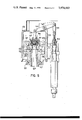
- FIG. 1 is a vertical sectional view of the device inserted in the drive between the cylinder and the dial in a machine equipped to form closed toes in accordance with the present invention
- FIG. 1a is a partial sectional view of a portion of FIG. 1;
- FIG. 2 is a sectional view taken along the line II--II of FIG. 1;
- FIG. 2a is a sectional of FIG. 2 when the arrangement is in the released position
- FIG. 3 is partial sectional view similar to FIG. 1, in the disengaging and stopping array of the plate;
- FIG. 4 is a diagrammatic view of the positioning of the device in the assembly of the machine
- FIG. 5 is a sectional view of an embodiment of the device in conventional machines not provided with the system for the forming of the closure;
- FIG. 6 is a sectional perspective view of a portion of the invention in the assembled state.
- FIG. 7 is an exploded perspective view of elements in FIG. 6.
- FIG. 4 there is diagrammatically indicated by 1, the machine base from which the cylinder 3 is developed.
- the dial 5 is arranged coaxially and overlying the cylinder 3, and is actuated in rotation by a drive which includes a shaft 7, the device 9 to be described, and an additional shaft 11.
- the supporting structures of the several members are not shown, while the device 9 is denoted only by its size.
- the shaft 11 which is the output shaft of the device to actuate the plate -- is driven in rotation by a bevel pinion 13 meshing on a toothed pinion 15 borne by a tubular shaft 17.
- the latter encloses the shaft 7 and is mounted by means of bearings 19, 21 on the frame 23.
- two disc expansions 25 and 27, connected by a spacer 29, define two front tooth profiles 31 and 33 opposite each other.
- the two teeth are appropriately offset in relation to the desired shift or phase displacement for the dial 5 with respect to the cylinder (for example of 180°) and to the drive ratio between the unit 17, 27 and the dial.
- the phase displacement is useful to obtain a closed toe.
- the upper disc expansion 27 extends with a tubular shell 35 always contained in the frame 23.
- the shaft 7 is capable of axially sliding within the rotor formed by the members 17, 25, 29, 27, 35 which essentially represent the clutch driven member.
- the shaft 7 represents the drive shaft, and is provided with a grooved sliding profile for its own actuation.
- the ratio of member 17 through 15, 13, 11 and the conical couple to the dial
- the teeth 31 and 33 should be at 90° between each other, so that the dial can be phase-displaced 180° every time.
- the lower splined end 7X of shaft 7, which matches with a grooved hole, corresponding to it, of a gear M.
- the latter is a drive member in a fixed position and transmits the motion to the shaft 7, when this moves axially according to the double arrow.
- the assembly of members 17, 25, 29, 27 and 35 matches with shaft 7 not with a grooved profile but with the teeth 31 (or 33) on one side and 39 on the other side.
- the shaft 7 integrally carries a glass structure 37 provided with a tooth 39 capable of being engaged in the front teeth 31 and 33 alternatively, with the axial movement of the shaft 7 and of the glass-shaped member 37. Passing from the engagement with one to the engagement with the other of the teeth 31 and 33, a delay is determined in the driven section 27, 29, 25, 17, 11 of the drive towards the plate 5. In the passage from one coupling to the other the entrained part 27, 29, 25 rotates slightly less than the drive part 7, 37 and every time in the particular case, remains behind for 180°.
- the members 7, 37 either from one or from the other of the engaging positions may be moved into an intermediate axial position between said two engaging positions, in which (see FIG. 3) the tooth 39 remains displaced between the two teeth 31 and 33 without meshing either with one or the other thereof.
- the glass-shaped member 37 is engaged by means of a bearing 41 with a slidable but not rotating member denoted by 43.
- the latter may slide within the tubular shell 35 and within the upper section 23A of the frame 23.
- this member 43 there is provided a small lever 45 linked in 47 to the frame 23, 23A and engaging with the inner end into a notch of the member 43.
- the lever 45 is controlled by the program drum.
- a flexible tie rod cable 51 which, by means of a spring 53, acts (against an elastic action) on a member 55 bound to the linkage 49. It also forms a profile 55A capable of operating in a conventionally known manner; levers 57 designed to slightly brake the driven member by acting on the expansion or shoe 55, during the passage from one to the other of the two end engaging positions.
- the two engaging positions are both kept elastically, one through the spring 53 in series with the cable 51, and the other by means of the spring 59 overcome by the traction action of the cable 51.
- the device according to the present invention allows the attainment of an intermediate position from one or from the other of the engaging positions, and the overcoming of the action of one or of the other of the springs.
- cable 51 When, for example, cable 51 is pulled downwardly, it pushes downwardly member 55, 55A -- through the very strong spring 53 -- compressing the slighter spring 59. If for any reason member 55 is not lowered, then spring 53 is compressed instead of causing the breakage of some member.
- spring 59 brings again upwards member 55 previously lowered, and the rising of member 55 causes the return upwardly of cable 51 through the spring 57.
- the tie rod or cable 51 has at the upper end a head 51X, against which spring 57 rests.
- a diametral latch 63 which is capable of assuming an inner position with respect to member 43 (see FIG. 2) or a projecting position wherein it may penetrate into the triangular window seat 61. In the inner position of the latch 63, any axial movement of the unit formed by the non-rotary section 43 and by the rotary sections 7 and 37 is possible, and any rotation of the driven member, of which the shell 35 is a part, is possible.
- the latch 63 in a manner to be described, is resiliently stressed to, it may penetrate into the window 61 of the rotating shell 35, whatever the axial position of the axially movable unit and the engaging position of the tooth 39 with one or the other of the teeth 31 and 33.
- the latch 63 is re-entered, and then the control imposed by the program drum through the drive 51, 55, 49, 45 determines the desired engagement on one side or on the other of the front tooth profiles 31, 33, according to the program requirements.
- the latch control is actuated (see FIG. 2) through a small lever 65 linked in 67 with the member 43 and operated by a tie rod 69 actuated through the small spring 71 by a cable 73.
- This cable is actuated by a track especially provided therefor on the program chain. This track imposes a movement of the cable 73, and thus of the lever 65 to it to project and thereby to lock the dial, during the periods of the fabric forming, when there is no necessity of the dial or of the so-called saw shearing device or other device provided on the plate to shear lengths of the yarns which come out or enter into working.
- saw shearing device or other device provided on the plate to shear lengths of the yarns which come out or enter into working.
- control of the cable 73 determines the loading of the spring 71 to cause the latch 63 to project, and the latter projects as soon as it finds the window 61 which passes in front thereof, during the rotation of the member 35.
- the spring 75 is active for the return.
- FIG. 5 there is shown an embodiment wherein there is provided only a seizing and disengagement clutch between a drive member and a driven member of the drive to the dial.
- a shaft 107 transmits the motion from the machine body and respectively from the cylinder.
- a tubular shaft is indicated coaxial to the shaft 107, which tubular shaft is assembled on bearings one of which is denoted by 121.
- Shaft 117 transmits the motion to the plate through bevel gears couplings or the like.
- the clutch which includes two disc expansions 125 and 127 coupled by means of a spacer 129.
- the expansion 125 has one or more front teeth 131, while the opposite expansion 127 has an inner surface 127A without teeth.
- a member 137 is sliding back and forth and this member is rotationally coupled to the shaft 107.
- the unit 107, 137 is capable of sliding axially there being provided a rotational binding coupling sliding axially between a portion of the drive in a fixed position and the shaft 107.
- the member 137 contains a bearing 141, whose inner ring (race) is borne by a composite core 143, which is not rotating.
- the core 143 through a small crank 144, is connected to a small lever 145 linked via 147 to the member 23.
- This second embodiment allows the possibility of providing merely the engagement and the disengagement with a clutch having only two positions, while in the previous embodiment, the clutch had three positions to obtain the shift besides the disengagement.
- the coupling position is obtained by well defined relative angular positions.
- the seat 61 may be replaced by two opposite inclined profiles, as for instance two helical profiles.
Landscapes
- Engineering & Computer Science (AREA)
- Textile Engineering (AREA)
- Knitting Machines (AREA)
- Treatment Of Fiber Materials (AREA)
Applications Claiming Priority (2)
| Application Number | Priority Date | Filing Date | Title |
|---|---|---|---|
| IT9581/73 | 1973-08-07 | ||
| IT9581/73A IT992223B (it) | 1973-08-07 | 1973-08-07 | Congegno di trasmissione del moto al disco o platorello degli uncini con innesto di sfasamento del plato rello |
Publications (1)
| Publication Number | Publication Date |
|---|---|
| US3974663A true US3974663A (en) | 1976-08-17 |
Family
ID=11132451
Family Applications (1)
| Application Number | Title | Priority Date | Filing Date |
|---|---|---|---|
| US05/495,148 Expired - Lifetime US3974663A (en) | 1973-08-07 | 1974-08-06 | Drive unit in circular hosiery machines for a dial with plate shift clutch |
Country Status (7)
| Country | Link |
|---|---|
| US (1) | US3974663A (it) |
| JP (1) | JPS5070646A (it) |
| DE (1) | DE2435929A1 (it) |
| ES (1) | ES428950A1 (it) |
| FR (1) | FR2240313B3 (it) |
| GB (1) | GB1472584A (it) |
| IT (1) | IT992223B (it) |
Cited By (6)
| Publication number | Priority date | Publication date | Assignee | Title |
|---|---|---|---|---|
| US5203184A (en) * | 1990-11-15 | 1993-04-20 | S.F.I.M. S.R.L. | Single-cylinder circular machine with improved platen actuation, in particular for manufacturing socks, stockings and the like |
| US5285662A (en) * | 1991-12-17 | 1994-02-15 | S.F.I.M. S.R.L. | Single-cylinder circular knitting machine for manufacturing socks and stockings or the like |
| CZ298009B6 (cs) * | 2000-03-01 | 2007-05-23 | UNIPLET TREBÍC, a.s. | Spojka pro pohon odklopného prístrojového talíre |
| CN102978822A (zh) * | 2012-08-24 | 2013-03-20 | 东阳市创亿针织机械有限公司 | 袜机离合器控制机构 |
| CN102995280A (zh) * | 2012-08-24 | 2013-03-27 | 东阳市创亿针织机械有限公司 | 袜机离合器 |
| ITBS20130150A1 (it) * | 2013-10-24 | 2015-04-25 | Santoni & C Spa | Macchina tessile circolare con meccanismo di innesto e sgancio del platorello del gruppo platò |
Citations (15)
| Publication number | Priority date | Publication date | Assignee | Title |
|---|---|---|---|---|
| US2070654A (en) * | 1935-03-04 | 1937-02-16 | Jr Robert A Gibbs | Double sole attachment for knitting machines |
| US2213454A (en) * | 1938-04-23 | 1940-09-03 | Grace Hosiery Mills Inc | Knitting machine |
| US2392719A (en) * | 1944-07-19 | 1946-01-08 | Kinney Mfg Company | Clutch |
| US2812651A (en) * | 1955-03-07 | 1957-11-12 | Midway Hosiery Mills Inc | Knitting machine |
| DE1031079B (de) * | 1954-05-29 | 1958-05-29 | Philips Patentverwaltung | Scheibenkupplung |
| US2841970A (en) * | 1955-06-24 | 1958-07-08 | Wildt & Co Ltd | Control mechanisms for knitting machines |
| US2844014A (en) * | 1954-04-07 | 1958-07-22 | Moretta Giuseppe | Drive transmission in circular hosiery and knitting machines with compensation of the wear in the gear teeth |
| US3021699A (en) * | 1962-02-20 | Clutch operating means for knitting machines | ||
| US3112819A (en) * | 1959-07-02 | 1963-12-03 | Xerox Corp | Clutch mechanism |
| US3139742A (en) * | 1962-08-01 | 1964-07-07 | Acme Mccrary Corp | Apparatus for varying the number of courses in knitted articles |
| US3252307A (en) * | 1963-02-15 | 1966-05-24 | Textile Machine Works | Yarn severing means for knitting machines |
| US3340707A (en) * | 1964-03-26 | 1967-09-12 | Scott & Williams Inc | Methods and machines for stocking production |
| US3399551A (en) * | 1957-04-09 | 1968-09-03 | Billi Giorgio | Circular knitting machine for manufacture of stockings |
| US3791175A (en) * | 1972-05-18 | 1974-02-12 | Rockwell International Corp | Safety device for dial transfer cams |
| US3913357A (en) * | 1972-12-29 | 1975-10-21 | Lonati Cost Mecc | Dial operated stocking toe closer |
-
1973
- 1973-08-07 IT IT9581/73A patent/IT992223B/it active
-
1974
- 1974-07-24 GB GB3262674A patent/GB1472584A/en not_active Expired
- 1974-07-25 DE DE2435929A patent/DE2435929A1/de active Pending
- 1974-08-05 ES ES428950A patent/ES428950A1/es not_active Expired
- 1974-08-05 JP JP49089143A patent/JPS5070646A/ja active Pending
- 1974-08-06 US US05/495,148 patent/US3974663A/en not_active Expired - Lifetime
- 1974-08-06 FR FR7427293A patent/FR2240313B3/fr not_active Expired
Patent Citations (15)
| Publication number | Priority date | Publication date | Assignee | Title |
|---|---|---|---|---|
| US3021699A (en) * | 1962-02-20 | Clutch operating means for knitting machines | ||
| US2070654A (en) * | 1935-03-04 | 1937-02-16 | Jr Robert A Gibbs | Double sole attachment for knitting machines |
| US2213454A (en) * | 1938-04-23 | 1940-09-03 | Grace Hosiery Mills Inc | Knitting machine |
| US2392719A (en) * | 1944-07-19 | 1946-01-08 | Kinney Mfg Company | Clutch |
| US2844014A (en) * | 1954-04-07 | 1958-07-22 | Moretta Giuseppe | Drive transmission in circular hosiery and knitting machines with compensation of the wear in the gear teeth |
| DE1031079B (de) * | 1954-05-29 | 1958-05-29 | Philips Patentverwaltung | Scheibenkupplung |
| US2812651A (en) * | 1955-03-07 | 1957-11-12 | Midway Hosiery Mills Inc | Knitting machine |
| US2841970A (en) * | 1955-06-24 | 1958-07-08 | Wildt & Co Ltd | Control mechanisms for knitting machines |
| US3399551A (en) * | 1957-04-09 | 1968-09-03 | Billi Giorgio | Circular knitting machine for manufacture of stockings |
| US3112819A (en) * | 1959-07-02 | 1963-12-03 | Xerox Corp | Clutch mechanism |
| US3139742A (en) * | 1962-08-01 | 1964-07-07 | Acme Mccrary Corp | Apparatus for varying the number of courses in knitted articles |
| US3252307A (en) * | 1963-02-15 | 1966-05-24 | Textile Machine Works | Yarn severing means for knitting machines |
| US3340707A (en) * | 1964-03-26 | 1967-09-12 | Scott & Williams Inc | Methods and machines for stocking production |
| US3791175A (en) * | 1972-05-18 | 1974-02-12 | Rockwell International Corp | Safety device for dial transfer cams |
| US3913357A (en) * | 1972-12-29 | 1975-10-21 | Lonati Cost Mecc | Dial operated stocking toe closer |
Cited By (9)
| Publication number | Priority date | Publication date | Assignee | Title |
|---|---|---|---|---|
| US5203184A (en) * | 1990-11-15 | 1993-04-20 | S.F.I.M. S.R.L. | Single-cylinder circular machine with improved platen actuation, in particular for manufacturing socks, stockings and the like |
| US5285662A (en) * | 1991-12-17 | 1994-02-15 | S.F.I.M. S.R.L. | Single-cylinder circular knitting machine for manufacturing socks and stockings or the like |
| CZ298009B6 (cs) * | 2000-03-01 | 2007-05-23 | UNIPLET TREBÍC, a.s. | Spojka pro pohon odklopného prístrojového talíre |
| CN102978822A (zh) * | 2012-08-24 | 2013-03-20 | 东阳市创亿针织机械有限公司 | 袜机离合器控制机构 |
| CN102995280A (zh) * | 2012-08-24 | 2013-03-27 | 东阳市创亿针织机械有限公司 | 袜机离合器 |
| CN102995280B (zh) * | 2012-08-24 | 2014-05-14 | 东阳市创亿针织机械有限公司 | 袜机离合器 |
| ITBS20130150A1 (it) * | 2013-10-24 | 2015-04-25 | Santoni & C Spa | Macchina tessile circolare con meccanismo di innesto e sgancio del platorello del gruppo platò |
| WO2015059592A1 (en) * | 2013-10-24 | 2015-04-30 | Santoni S.P.A. | Circular knitting machine with an engaging and disengaging mechanism of the hook plate of the dial group |
| US10240266B2 (en) | 2013-10-24 | 2019-03-26 | Santoni S.P.A. | Circular knitting machine with an engaging and disengaging mechanism of the hook plate of the dial group |
Also Published As
| Publication number | Publication date |
|---|---|
| IT992223B (it) | 1975-09-10 |
| GB1472584A (en) | 1977-05-04 |
| JPS5070646A (it) | 1975-06-12 |
| ES428950A1 (es) | 1976-08-16 |
| FR2240313A1 (it) | 1975-03-07 |
| FR2240313B3 (it) | 1977-06-03 |
| DE2435929A1 (de) | 1975-02-20 |
Similar Documents
| Publication | Publication Date | Title |
|---|---|---|
| AU646360B2 (en) | Automatic washer basket and agitator drive system | |
| US3974663A (en) | Drive unit in circular hosiery machines for a dial with plate shift clutch | |
| US4283928A (en) | Transmission for washing machine | |
| US4319495A (en) | Coupling and uncoupling apparatus | |
| JP3863947B2 (ja) | 糸処理部材を引戻しかつ推進する装置 | |
| US3388681A (en) | Speed change mechanism of a sewing machine | |
| US2404850A (en) | Driving and stopping mechanism for sewing machines | |
| US2529379A (en) | Arrangement for the control of a variable-speed mechanism | |
| US3071090A (en) | Stop motion mechanism for sewing machines | |
| US2222766A (en) | Automatic change speed transmission | |
| US3285378A (en) | Ring rail wind-down unit for spinning machine | |
| US1355159A (en) | Driving and stopping mechanism | |
| JPS6040536B2 (ja) | 回転ドビ−機におけるキ−継手の制御装置 | |
| US1241710A (en) | Sewing-machine. | |
| GB2037909A (en) | Clutches | |
| US2520013A (en) | Clutch mechanism | |
| GB1489460A (en) | Sewing machines | |
| US2081838A (en) | Clutch and control mechanism therefor | |
| US1248811A (en) | Stop-motion mechanism for sewing-machines. | |
| US362344A (en) | Reversing mechanism | |
| GB2053984A (en) | Improvements in or relating to knitting machines | |
| US1175893A (en) | Speed-changing mechanism for power-driven machines. | |
| GB1035725A (en) | Improvements in or relating to motor drive and needle positioning mechanisms of sewing machines | |
| US2208070A (en) | Knitting machine | |
| JPH0160095B2 (it) |