US4000681A - Mine bolt tension indicator - Google Patents
Mine bolt tension indicator Download PDFInfo
- Publication number
- US4000681A US4000681A US05/576,416 US57641675A US4000681A US 4000681 A US4000681 A US 4000681A US 57641675 A US57641675 A US 57641675A US 4000681 A US4000681 A US 4000681A
- Authority
- US
- United States
- Prior art keywords
- washer
- bolt
- tension
- distance
- indicating
- Prior art date
- Legal status (The legal status is an assumption and is not a legal conclusion. Google has not performed a legal analysis and makes no representation as to the accuracy of the status listed.)
- Expired - Lifetime
Links
Images



Classifications
-
- F—MECHANICAL ENGINEERING; LIGHTING; HEATING; WEAPONS; BLASTING
- F16—ENGINEERING ELEMENTS AND UNITS; GENERAL MEASURES FOR PRODUCING AND MAINTAINING EFFECTIVE FUNCTIONING OF MACHINES OR INSTALLATIONS; THERMAL INSULATION IN GENERAL
- F16B—DEVICES FOR FASTENING OR SECURING CONSTRUCTIONAL ELEMENTS OR MACHINE PARTS TOGETHER, e.g. NAILS, BOLTS, CIRCLIPS, CLAMPS, CLIPS OR WEDGES; JOINTS OR JOINTING
- F16B31/00—Screwed connections specially modified in view of tensile load; Break-bolts
- F16B31/02—Screwed connections specially modified in view of tensile load; Break-bolts for indicating the attainment of a particular tensile load or limiting tensile load
- F16B31/028—Screwed connections specially modified in view of tensile load; Break-bolts for indicating the attainment of a particular tensile load or limiting tensile load with a load-indicating washer or washer assembly
-
- E—FIXED CONSTRUCTIONS
- E21—EARTH OR ROCK DRILLING; MINING
- E21D—SHAFTS; TUNNELS; GALLERIES; LARGE UNDERGROUND CHAMBERS
- E21D21/00—Anchoring-bolts for roof, floor in galleries or longwall working, or shaft-lining protection
- E21D21/02—Anchoring-bolts for roof, floor in galleries or longwall working, or shaft-lining protection having means for indicating tension
Definitions
- This invention relates to tension indicating devices and more particularly relates to devices for visually indicating the tension in mine roof bolts which are also known as mine wall bolts, rock bolts and the like.
- the prior art includes several devices for indicating the tension in mine roof bolting. These devices may be seen by reference to U.S. Pat. Nos. 2,464,152; 3,104,645; 3,169,440 and 3,329,058. These devices are not totally satisfactory and have not found univeral or wide use because they were not passive and easily seen from a distance, they indicated over or under tension only, they were complicated and expensive to produce and/or install and/or they required electronic apparatus. More recent prior art devices have utilized chemical substances which change color as the tension in the bolt changed. These devices have also been found to be less than totally satisfactory as they are relatively expensive and/or difficult to see.
- the most common mine bolt tension testing and monitoring system comprises a highly paid employee who manually tests mine bolts with a torque wrench.
- the drawbacks of the prior art have been overcome to the extent that a relatively simple and inexpensive device is provided for visually indicating the tension in a mine roof bolt or the like.
- the device may be permanently installed for passive monitoring of the bolt or may include a removable indicating means to prevent tampering therewith and/or unintentional damage thereto.
- the device of the present invention has an indicating member which may assume a first position corresponding to greater than predetermined maximum tension in the bolt, a second position corresponding to less than predetermined acceptable minimum tension in the bolt or positions intermediate the first and second positions corresponding to a tension in the bolt intermediate the predetermined maximum and predetermined acceptable minimum.
- a spring washer preferably a helical washer, which is inserted inbetween the head of the bolt and the backing plate, or other member, against which the head will bear as the bolt is tightened.
- the spring washer will have an expanded condition, corresponding to no compression thereon and a flattened fully compressed condition corresponding to the compression exerted thereon by the bolt head and the plate when greater than the predetermined maximum tension is in the bolt.
- a pivot member preferably a pivot pin or pivot aperture, is located on an exterior surface of the washer. The pivot member will be axially spaced a first distance from the plate when the washer is fully compressed and will be axially spaced a second distance from the plate when the washer is subjected to a compression equaling the predetermined acceptable minimum tension in the monitored bolt.
- a highly visible elongated indicating member, or flag is pivotally mounted at one end thereof, permanently or removably, to the pivot member.
- the free end of the indicating device under the influence of gravity, will tend to pivot downwardly such that the indicating device would assume a vertical position.
- the indicating member in a substantially horizontal or first position, has a surface which will engage the plate when the washer is fully compressed to maintain the indicating member in the first position.
- the surface has an outer extremity on the one end thereof which is spaced from the point at which the indicating member is pivotally mounted by a distance equal to or less than the axial separation of the pivot member from the plate when the washer is subject to a compression equal to the minimum allowable tension in the bolt.
- the surface of the indicating member will gradually disengage the plate allowing the indicating member to angle away from its first, substantially horizontal position, until the surface totally disengages the plate and the indicating member hangs vertically in its second indicating position.
- Another object of the present invention is to provide a relatively simple and economical mechanical device for visually indicating if a mine roof bolt or the like is subject to greater than a predetermined maximum tension, less than predetermined minimum acceptable tension, or a tension greater than the predetermined minimum acceptable but less than the predetermined maximum.
- FIG. 1 is a perspective view of a portion of a mine tunnel showing representative "mine roof” or “rock” bolts in position to support the roof.
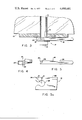
- FIG. 2 is a enlarged cross-section showing one of the mine roof or rock bolts in FIG. 1 and illustrating the tension indicating device of the present invention.
- FIG. 3 is an enlarged view of the tension indication device of the present invention.
- FIG. 4 is a front elevational view of the spring washer utilized in connection with the present invention.
- FIG. 5 is a front elevational view of the indicating device utilized in connection with the present invention.
- FIG. 5A is an enlarged fragmentary view of the indicating member of FIG. 5.
- FIG. 6 is an enlarged view of the tension indicating device of the present invention indicating that the tension in a monitored mine roof bolt is equal to or greater than a predetermined maximum tension.
- FIG. 7 is an enlarged view of the tension indicating device of the present invention indicating that the tension in a monitored mine roof bolt is less than a predetermined acceptable minimum tension.
- FIG. 8 is an enlarged view of the tension indicating device of the present invention indicating that the tension in a monitored mine roof bolt is greater than the predetermined acceptable minimum but less than the predetermined maximum tension.
- FIGS. 9A, 9B and 9C are cross-sectional views of three of the most commonly used mine roof backing plates.
- FIGS. 10A, 10B, 10C, 10D, 10E and 10F are top and side views of conditions commonly encountered in mine roof bolt heads.
- FIG. 11 is a top view of an alternate embodiment of tension indicating member.
- FIG. 12 is a side elevational view of the tension indicating member of FIG. 11.
- FIG. 12A is an enlarged fragmentary view of the indicating member of FIG. 12.
- FIG. 13 is a top view of the helical spring washer of the present invention.
- FIG. 14 is a sectional view of the helical spring washer of the present invention taken along line A-A in FIG. 13.
- FIG. 15 is a top view of an alternate embodiment of the helical spring washer of the present invention.
- FIG. 16 is an alternate embodiment of the tension indication device of the present invention.
- the roof 10 of a mine tunnel 11 may be supported by a plurality of "rock" or “mine roof” bolts generally bearing the reference character 12.
- Such bolts are generally 5/8 inch or 3/4 inch in diameter and are 31/2 feet to 6 feet in length.
- the bolts be tightened to the prescribed tension and that they be maintained at this tension at all times.
- a typical rock bolt 12 is shown installed in a drilling 13 formed in the rock strata and extending upwardly from the surface of the roof 10.
- An expansion shell 14 is provided at that end of the rock or mine roof bolt 12 which lies within the drill-line 13.
- the expansion shell 14 may be of any suitable construction and forms no part of the present invention. In general, expansion shells are constructed so that as tension is applied to the bolt, the shell will expand radially outwardly to grip the walls of the drilling 13 and to hold the bolt firmly within the drilling.
- a mine roof backing plate 16 is typically interposed the head 15 of the bolt 12 and the roof 10 of the mine tunnel.
- the head 15 of the bolt may be replaced by a threaded end and nut construction as is well known in the art and the term “bolt” as used herein is intended to encompass such construction.
- the indication device 17 of the present invention is interposed the head 15 of the bolt 12 and the plate 16. It is understood the terms “backing plate” or “plate” will apply to the surface against which the bolt and/or indication device bears.
- the indication device comprises a resilient, spring washer 18 and an indication member 19 pivotally mounted to the washer 18.
- the bolt 12 will be placed in tension and the rock strata 10a, 10b and 10c constituting the roof 10 will be placed in compression.
- the spring washer 18 is resiliently compressed, or flattened, between the plate 16 and head 15 of the bolt 12.
- the tension indication device, 17, of the present invention may be seen in greater detail by reference to FIGS. 3-5.
- the mine roof bolt 12 is shown as received in a drilling 13 in the rock strata and retained by an anchor or expansion member (not shown) of conventional type.
- a backing plate 16 is utilized to provide a large bearing surface for the bolt against the mine roof 10.
- the tension indication device 17 is interposed the head 15 of the bolt 12 and the backing plate 16.
- the indicating device 17 comprises a spring washer 18 and an indicating member 19 which may be seen by reference to FIGS. 4 and 5 respectively.
- the washer 18 is interposed the head 15 of the bolt 12 and the backing plate 16.
- the tension in bolt 12 will correspond to the compression between the head 15 of the bolt 12 and the backing plate 16.
- the spring washer 18 is thus subject to a compression equal to the tension in bolt 12 and a measurement of the compression in the washer 18 will provide an equally accurate measurement of the tension in bolt 12.
- the spring washer 18 illustrated is a helical washer having a spring constant which allows the washer to become substantially fully compressed and flattened, FIG. 3 and FIG. 6, upon the application of a compressive force equal to at least the predetermined maximum tension in the bolt 12. It is appreciated that any type of spring washer having sufficient resiliency and spring constant may be utilized.
- the spring washer in its fully uncoiled, uncompressed condition is illustrated in FIG. 4.
- the preferred helical spring washer see FIGS. 14 and 15, is specially configured to be thicker at its outer radius 20 than at its inner radius 21 to present a uniform outer bearing surface against the bolt head 15 and the backing plate 16 may bear.
- the spring washer is selected with a spring constant such that the washer will be somewhat compressed when subject to a compression equal to the predetermined minimum acceptable tension in the bolt.
- a pivot member or pin 22 is provided on a radially outer surface 24 of the washer 18.
- the pivot member is preferably a pivot pin and may be a screw, rivet, welded shaft, staked shaft or the like.
- the pivot member 122 may also be a pivot bore for rotatably receiving a pivot pin.
- FIG. 6 when the washer is fully compressed, i.e., subject to a compression equal to or greater than the predetermined maximum tension in bolt 12, the pivot pin 22 will be spaced from the backing plate 16 by a first distance A.
- FIG. 6 when the washer is fully compressed, i.e., subject to a compression equal to or greater than the predetermined maximum tension in bolt 12, the pivot pin 22 will be spaced from the backing plate 16 by a first distance A.
- FIG. 6 when the washer is fully compressed, i.e., subject to a compression equal to or greater than the predetermined maximum tension in bolt 12, the pivot pin 22 will be spaced from the backing plate 16 by a first distance A.
- the indicating member 19 is an elongated body which is provided with a pivot mount 26 at one end thereof.
- the pivot mount 26 is designed to engage the pivot member 22 of washer 18 to pivotally mount the indication member 19 to the washer 18.
- Indication member 19 may be designed for relatively permanent or for relatively easily removable mounting to the washer 18.
- the indication member 19 is preferably large and easily visible from a distance.
- the indication member 19 may be molded or stamped of a luminous plastic or may be a metallic device with a luminous coating thereon.
- the indication member 19 has a surface or face 28 for engagement with the backing plate which is spaced from the pivot mount by a distance D which is generally equal to distance A.
- the extremity 30 of face 28 at the end of the indicating member at which it is pivotally mounted to the washer 18 is separated from the pivot mount by a distance E which is generally equal to distance B. Face 28 may, of course, be continued.
- the operation of the indicating device 17 may be seen by reference to FIGS. 6-8.
- the spring washer 18 is fully compressed, the pivot pin 22 is spaced from the backing plate by distance A and face 28 of indicating member 19 is pressed against the backing plate 16 maintaining the indicator 19 in a generally horizontal or first position indicating that greater than the predetermined tension is in monitored bolt 12.
- the washer 18 is expanded or uncoiled by a degree sufficient to move pivot pin 22 a distance at least as great as distance B from the backing plate 16.
- the indicating device is hanging vertically, or in a second position indicating less than predetermined minimal acceptable tension in bolt 12, as both face 28 and extremity 30 have been disengaged from the backing plate 16.
- the washer 18 has expanded or uncoiled by a degree sufficient to move pivot pin 22 a distance C from the backing plate 16.
- the extremity 30 of the face 28 of the indicating member 19 is engaged by the backing plate 16 and the indicating member 19 hangs at an angle ⁇ , generally between 5° and 70° , with respect to the horizontal indicating that the tension in bolt 12 is greater than the predetermined acceptable minimum but less than the predetermined maximum.
- the indicating device in FIG. 8 is thus visually indicating that the tension in monitored bolt 12 is within an acceptable range.
- the indication device 17 of the present invention may be selected to indicate tension conditions in a bolt 12 over a selectively variable range.
- FIG. 16 an alternate embodiment 217 of the invention is illustrated.
- the bolt 212 is driven into a substantially vertical wall 210 of the mine tunnel 211.
- the spring washer 218 and bolt 212 and plate 216 are identical in function to washer 18, bolt 12 and plate 16 described above.
- the indication member 219 is generally identical to indicator member 19 described above except that an end or vertical face 228 is designed to contact the plate 216 when the indication member is in the first or substantially horizontal position. With the exception of the location of surface 228, the indicator 217 is identical in function to indicator 17 described above and will not be described in greater detail.
- FIG. 9 illustrates three types of commonly used backing plates.
- FIG. 10 illustrates the non standard conditions often found in connection with the heads of mine roof bolts.
- the indication member 319 is substantially identical to indication members 19 and 219 described above except that the free end of elongated body is offset the end at which to indicating member is pivotally mounted by a stepped portion 340.
- the stepped portion 340 allows the body to clear and be uneffected by the various types of backing plates and/or non-standard bolt heads.
Landscapes
- Engineering & Computer Science (AREA)
- General Engineering & Computer Science (AREA)
- Mining & Mineral Resources (AREA)
- Mechanical Engineering (AREA)
- Structural Engineering (AREA)
- Life Sciences & Earth Sciences (AREA)
- General Life Sciences & Earth Sciences (AREA)
- Geochemistry & Mineralogy (AREA)
- Geology (AREA)
- Force Measurement Appropriate To Specific Purposes (AREA)
- Rock Bolts (AREA)
Priority Applications (4)
| Application Number | Priority Date | Filing Date | Title |
|---|---|---|---|
| US05/576,416 US4000681A (en) | 1975-05-12 | 1975-05-12 | Mine bolt tension indicator |
| GB18984/76A GB1537518A (en) | 1975-05-12 | 1976-05-07 | Mine bolt tension indicator |
| CA252,131A CA1044053A (en) | 1975-05-12 | 1976-05-10 | Mine bolt tension indicator |
| JP51053375A JPS593640B2 (ja) | 1975-05-12 | 1976-05-12 | 坑道におけるボルトの引張指示装置 |
Applications Claiming Priority (1)
| Application Number | Priority Date | Filing Date | Title |
|---|---|---|---|
| US05/576,416 US4000681A (en) | 1975-05-12 | 1975-05-12 | Mine bolt tension indicator |
Publications (1)
| Publication Number | Publication Date |
|---|---|
| US4000681A true US4000681A (en) | 1977-01-04 |
Family
ID=24304332
Family Applications (1)
| Application Number | Title | Priority Date | Filing Date |
|---|---|---|---|
| US05/576,416 Expired - Lifetime US4000681A (en) | 1975-05-12 | 1975-05-12 | Mine bolt tension indicator |
Country Status (4)
| Country | Link |
|---|---|
| US (1) | US4000681A (ja) |
| JP (1) | JPS593640B2 (ja) |
| CA (1) | CA1044053A (ja) |
| GB (1) | GB1537518A (ja) |
Cited By (22)
| Publication number | Priority date | Publication date | Assignee | Title |
|---|---|---|---|---|
| US4217849A (en) * | 1978-12-21 | 1980-08-19 | Brown Larry L | Mine roof warning indicator |
| US4293257A (en) * | 1980-03-17 | 1981-10-06 | Illinois Tool Works Inc. | Tension indicating washer |
| US4840521A (en) * | 1985-02-19 | 1989-06-20 | Framatome | Element for filtering stress variations in a bolted assembly |
| US5188494A (en) * | 1992-04-21 | 1993-02-23 | Itt Corporation | Torque indicator device and method for use with a threaded fastener |
| US20010000404A1 (en) * | 1997-04-24 | 2001-04-26 | Alfonso Losada | Power actuated fastener system |
| US20030133768A1 (en) * | 2002-01-11 | 2003-07-17 | Alfonso Losada | Fastener assembly having grooves for use with a power actuated gun |
| US20040188490A1 (en) * | 2002-11-05 | 2004-09-30 | Alfonso Losada | Power actuated gun with fastener feeding track and automatic firing |
| US20040188489A1 (en) * | 2002-10-18 | 2004-09-30 | Alfonso Losada | Power actuated gun with automatic firing |
| US20050034391A1 (en) * | 2000-12-03 | 2005-02-17 | Leek William F. | Automatic take-up device with internal spring |
| US20060201285A1 (en) * | 2005-03-09 | 2006-09-14 | Simpson Strong-Tie Company, Inc. | Limited access building connection |
| US20060263166A1 (en) * | 2005-05-18 | 2006-11-23 | Honeywell International Inc. | Devices and methods for monitoring fastener tension |
| WO2007137466A1 (fr) * | 2006-06-01 | 2007-12-06 | China University Of Mining And Technology | Appareil d'essai aléatoire, non destructif et dynamique, et procédé de vérification de l'état de contrainte d'un boulon d'ancrage |
| US20080245004A1 (en) * | 2007-04-06 | 2008-10-09 | Pryor Steven E | Automatic take-up device and in-line coupler |
| US8881478B2 (en) | 2012-06-22 | 2014-11-11 | Simpson Strong-Tie Company, Inc. | Ratcheting take-up device |
| US9394706B2 (en) | 2013-10-08 | 2016-07-19 | Simpson Strong-Tie Company, Inc. | Concrete anchor |
| US10060809B1 (en) | 2016-10-27 | 2018-08-28 | Larry C. Hoffman | Friction stabilizer pull tester and method |
| WO2020077370A1 (en) * | 2018-10-09 | 2020-04-16 | Epiroc Holdings South Africa (Pty) Ltd | Device for monitoring movement in a rock face |
| EP3748122A1 (en) | 2019-06-04 | 2020-12-09 | Sandvik Mining and Construction Tools AB | A tension indicator for a rock bolt |
| WO2021089353A1 (en) | 2019-11-08 | 2021-05-14 | Sandvik Mining And Construction Tools Ab | Visual indicator for correct torsion of a rock bolt |
| EP3910163A1 (en) | 2020-05-14 | 2021-11-17 | Sandvik Mining and Construction Tools AB | A tension indicator for a rock bolt |
| AU2019283864B2 (en) * | 2014-11-18 | 2021-12-09 | Illinois Tool Works Inc. | Fastening with load indicator |
| USRE48981E1 (en) | 2014-01-14 | 2022-03-22 | Simpson Strong-Tie Company Inc. | Thrust nut |
Families Citing this family (1)
| Publication number | Priority date | Publication date | Assignee | Title |
|---|---|---|---|---|
| GB2179459A (en) * | 1985-08-17 | 1987-03-04 | Rotabolt Ltd | Indicating tightness of fastening device |
Citations (10)
| Publication number | Priority date | Publication date | Assignee | Title |
|---|---|---|---|---|
| US1020748A (en) * | 1911-05-04 | 1912-03-19 | William J M Dobson | Belt-clamp. |
| US2725843A (en) * | 1951-06-01 | 1955-12-06 | Francis A E Koski | Sag indicator |
| US2781687A (en) * | 1954-02-24 | 1957-02-19 | Chrysler Corp | Assembly comprising calibrated bolt and calibrated deformable conical washer |
| DE1121370B (de) * | 1960-04-13 | 1962-01-04 | Eduard Wille Fa | Vorrichtung zum Pruefen bzw. Messen der Anzugskraft von in ein Werkstueck eingeschraubten Schrauben und zur entsprechenden Einstellung von maschinellen Schraubgeraeten |
| US3060731A (en) * | 1958-09-11 | 1962-10-30 | Herbert H Adise | Motion translator |
| US3072093A (en) * | 1960-02-16 | 1963-01-08 | Illinois Tool Works | Visible inspection fastener |
| US3104645A (en) * | 1961-03-22 | 1963-09-24 | Harrison Henry | Bolt stress indicator |
| US3161174A (en) * | 1963-08-06 | 1964-12-15 | Harrison Henry | Mine roof bolt tension indicator |
| US3179082A (en) * | 1961-08-22 | 1965-04-20 | William G B Mcclean | Expansion bolts |
| US3329058A (en) * | 1964-04-14 | 1967-07-04 | Cumming James Deans | Tension indicating washer |
-
1975
- 1975-05-12 US US05/576,416 patent/US4000681A/en not_active Expired - Lifetime
-
1976
- 1976-05-07 GB GB18984/76A patent/GB1537518A/en not_active Expired
- 1976-05-10 CA CA252,131A patent/CA1044053A/en not_active Expired
- 1976-05-12 JP JP51053375A patent/JPS593640B2/ja not_active Expired
Patent Citations (10)
| Publication number | Priority date | Publication date | Assignee | Title |
|---|---|---|---|---|
| US1020748A (en) * | 1911-05-04 | 1912-03-19 | William J M Dobson | Belt-clamp. |
| US2725843A (en) * | 1951-06-01 | 1955-12-06 | Francis A E Koski | Sag indicator |
| US2781687A (en) * | 1954-02-24 | 1957-02-19 | Chrysler Corp | Assembly comprising calibrated bolt and calibrated deformable conical washer |
| US3060731A (en) * | 1958-09-11 | 1962-10-30 | Herbert H Adise | Motion translator |
| US3072093A (en) * | 1960-02-16 | 1963-01-08 | Illinois Tool Works | Visible inspection fastener |
| DE1121370B (de) * | 1960-04-13 | 1962-01-04 | Eduard Wille Fa | Vorrichtung zum Pruefen bzw. Messen der Anzugskraft von in ein Werkstueck eingeschraubten Schrauben und zur entsprechenden Einstellung von maschinellen Schraubgeraeten |
| US3104645A (en) * | 1961-03-22 | 1963-09-24 | Harrison Henry | Bolt stress indicator |
| US3179082A (en) * | 1961-08-22 | 1965-04-20 | William G B Mcclean | Expansion bolts |
| US3161174A (en) * | 1963-08-06 | 1964-12-15 | Harrison Henry | Mine roof bolt tension indicator |
| US3329058A (en) * | 1964-04-14 | 1967-07-04 | Cumming James Deans | Tension indicating washer |
Cited By (36)
| Publication number | Priority date | Publication date | Assignee | Title |
|---|---|---|---|---|
| US4217849A (en) * | 1978-12-21 | 1980-08-19 | Brown Larry L | Mine roof warning indicator |
| US4293257A (en) * | 1980-03-17 | 1981-10-06 | Illinois Tool Works Inc. | Tension indicating washer |
| US4840521A (en) * | 1985-02-19 | 1989-06-20 | Framatome | Element for filtering stress variations in a bolted assembly |
| US5188494A (en) * | 1992-04-21 | 1993-02-23 | Itt Corporation | Torque indicator device and method for use with a threaded fastener |
| US7111767B2 (en) | 1997-04-24 | 2006-09-26 | Simpson Strong-Tie Company, Inc. | Power actuated fastener system |
| US20010000404A1 (en) * | 1997-04-24 | 2001-04-26 | Alfonso Losada | Power actuated fastener system |
| US20070012744A1 (en) * | 1997-04-24 | 2007-01-18 | Simpson Strong-Tie Company, Inc. | Power actuated fastener system |
| US7516582B2 (en) | 2000-12-03 | 2009-04-14 | Simpson Strong-Tie Company Inc. | Automatic take-up device with internal spring |
| US7509778B2 (en) | 2000-12-03 | 2009-03-31 | Simpson Strong-Tie Company, Inc. | Automatic take-up device with internal spring |
| US20050034391A1 (en) * | 2000-12-03 | 2005-02-17 | Leek William F. | Automatic take-up device with internal spring |
| US20030133768A1 (en) * | 2002-01-11 | 2003-07-17 | Alfonso Losada | Fastener assembly having grooves for use with a power actuated gun |
| US20040188489A1 (en) * | 2002-10-18 | 2004-09-30 | Alfonso Losada | Power actuated gun with automatic firing |
| US7249701B2 (en) | 2002-11-05 | 2007-07-31 | Simpson Strong-Tie Co., Inc. | Power actuated gun with fastener feeding track and automatic firing |
| US20040188490A1 (en) * | 2002-11-05 | 2004-09-30 | Alfonso Losada | Power actuated gun with fastener feeding track and automatic firing |
| US20070006691A1 (en) * | 2005-03-09 | 2007-01-11 | Simpson Strong-Tie Company, Inc. | Limited access building connection |
| US20060201285A1 (en) * | 2005-03-09 | 2006-09-14 | Simpson Strong-Tie Company, Inc. | Limited access building connection |
| US7168343B2 (en) | 2005-03-09 | 2007-01-30 | Simpson Strong-Tie Company, Inc. | Limited access building connection |
| US7296501B2 (en) | 2005-03-09 | 2007-11-20 | Simpson Strong-Tie Company, Inc. | Limited access building connection |
| US20060263166A1 (en) * | 2005-05-18 | 2006-11-23 | Honeywell International Inc. | Devices and methods for monitoring fastener tension |
| WO2007137466A1 (fr) * | 2006-06-01 | 2007-12-06 | China University Of Mining And Technology | Appareil d'essai aléatoire, non destructif et dynamique, et procédé de vérification de l'état de contrainte d'un boulon d'ancrage |
| US20080245004A1 (en) * | 2007-04-06 | 2008-10-09 | Pryor Steven E | Automatic take-up device and in-line coupler |
| US7905066B2 (en) | 2007-04-06 | 2011-03-15 | Simpson Strong-Tie Co., Inc. | Automatic take-up device and in-line coupler |
| US8881478B2 (en) | 2012-06-22 | 2014-11-11 | Simpson Strong-Tie Company, Inc. | Ratcheting take-up device |
| US9394706B2 (en) | 2013-10-08 | 2016-07-19 | Simpson Strong-Tie Company, Inc. | Concrete anchor |
| US9945115B2 (en) | 2013-10-08 | 2018-04-17 | Simpson Strong-Tie Company, Inc. | Concrete anchor |
| USRE48981E1 (en) | 2014-01-14 | 2022-03-22 | Simpson Strong-Tie Company Inc. | Thrust nut |
| AU2019283864B2 (en) * | 2014-11-18 | 2021-12-09 | Illinois Tool Works Inc. | Fastening with load indicator |
| US10060809B1 (en) | 2016-10-27 | 2018-08-28 | Larry C. Hoffman | Friction stabilizer pull tester and method |
| WO2020077370A1 (en) * | 2018-10-09 | 2020-04-16 | Epiroc Holdings South Africa (Pty) Ltd | Device for monitoring movement in a rock face |
| EP3748122A1 (en) | 2019-06-04 | 2020-12-09 | Sandvik Mining and Construction Tools AB | A tension indicator for a rock bolt |
| WO2020245081A1 (en) | 2019-06-04 | 2020-12-10 | Sandvik Mining And Construction Tools Ab | A tension indicator for a rock bolt |
| WO2021089353A1 (en) | 2019-11-08 | 2021-05-14 | Sandvik Mining And Construction Tools Ab | Visual indicator for correct torsion of a rock bolt |
| US12203372B2 (en) | 2019-11-08 | 2025-01-21 | Sandvik Mining And Construction Tools Ab | Visual indicator for correct torsion of a rock bolt |
| EP3910163A1 (en) | 2020-05-14 | 2021-11-17 | Sandvik Mining and Construction Tools AB | A tension indicator for a rock bolt |
| WO2021228981A1 (en) | 2020-05-14 | 2021-11-18 | Sandvik Mining And Construction Tools Ab | A tension indicator for a rock bolt |
| US12385396B2 (en) | 2020-05-14 | 2025-08-12 | Sandvik Mining And Construction Tools Ab | Tension indicator for a rock bolt |
Also Published As
| Publication number | Publication date |
|---|---|
| GB1537518A (en) | 1978-12-29 |
| CA1044053A (en) | 1978-12-12 |
| JPS593640B2 (ja) | 1984-01-25 |
| JPS51139109A (en) | 1976-12-01 |
Similar Documents
| Publication | Publication Date | Title |
|---|---|---|
| CA1044053A (en) | Mine bolt tension indicator | |
| US4047463A (en) | Tension indicator | |
| US3161174A (en) | Mine roof bolt tension indicator | |
| US5188494A (en) | Torque indicator device and method for use with a threaded fastener | |
| US3104645A (en) | Bolt stress indicator | |
| US4927305A (en) | Tightening device for threaded connectors | |
| US5185595A (en) | Rockbolt monitor | |
| US11131191B2 (en) | Sensing device for a rock bolt | |
| US12012856B2 (en) | Rock bolt assembly comprising a sensor assembly | |
| US4709654A (en) | Indicator for loose lug nuts | |
| US3329058A (en) | Tension indicating washer | |
| US4136556A (en) | Device to monitor movement of a surface | |
| US4904122A (en) | Anchoring device, such as a rock anchor | |
| US5791844A (en) | Portable winch crank for flatbed trailers | |
| US5207535A (en) | Push-on gripper plate for use with rock bolts | |
| US5064311A (en) | Mine roof support structure and method | |
| US3021927A (en) | Lap-lox fastener | |
| US3851560A (en) | Self-drilling expansion roof bolt | |
| US3960456A (en) | Incipient shear pin failure indicating means | |
| US3021747A (en) | Method and washer means including a calibrated rubber layer for measuring bolt tension | |
| US4740111A (en) | Friction washer for securing a wire mesh screening onto the protruding end of rock bolts | |
| US3908508A (en) | Strain indicator | |
| HU209188B (en) | Clamp signalling loading | |
| US4076291A (en) | Tamper-resistant electric meter sealing ring | |
| US4410296A (en) | Rock bolt overload warning device |