US4044958A - Edge mill - Google Patents
Edge mill Download PDFInfo
- Publication number
- US4044958A US4044958A US05/602,654 US60265475A US4044958A US 4044958 A US4044958 A US 4044958A US 60265475 A US60265475 A US 60265475A US 4044958 A US4044958 A US 4044958A
- Authority
- US
- United States
- Prior art keywords
- mill according
- edge mill
- track
- cross head
- grinding
- Prior art date
- Legal status (The legal status is an assumption and is not a legal conclusion. Google has not performed a legal analysis and makes no representation as to the accuracy of the status listed.)
- Expired - Lifetime
Links
- 239000000463 material Substances 0.000 claims abstract description 5
- 239000000919 ceramic Substances 0.000 claims abstract description 3
- 238000004519 manufacturing process Methods 0.000 claims abstract description 3
- 239000012530 fluid Substances 0.000 claims 1
- 238000005096 rolling process Methods 0.000 abstract 1
- 238000010276 construction Methods 0.000 description 5
- 230000005540 biological transmission Effects 0.000 description 3
- 125000006850 spacer group Chemical group 0.000 description 3
- 229910010293 ceramic material Inorganic materials 0.000 description 1
- 238000012986 modification Methods 0.000 description 1
- 230000004048 modification Effects 0.000 description 1
- 238000010008 shearing Methods 0.000 description 1
Images
Classifications
-
- B—PERFORMING OPERATIONS; TRANSPORTING
- B02—CRUSHING, PULVERISING, OR DISINTEGRATING; PREPARATORY TREATMENT OF GRAIN FOR MILLING
- B02C—CRUSHING, PULVERISING, OR DISINTEGRATING IN GENERAL; MILLING GRAIN
- B02C15/00—Disintegrating by milling members in the form of rollers or balls co-operating with rings or discs
- B02C15/14—Edge runners, e.g. Chile mills
Definitions
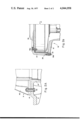
- FIGS. 2a and 2A show further enlarged fragmentary views of structure of FIGS. 1 and 2 of the drawings.
- the present invention relates to an edge mill, for the crushing of materials for the manufacture of ceramic articles or the like, having a grinding track extending approximately horizontally, a cross head located above the track and rotatably mounted on a stationary track axle which extends approximately at a right angle to the grinding track.
- Driver cranks are mounted on the cross head, and grinding rollers are provided running on the grinding track and rotatably mounted on the cranks.
- the grinding rollers are drivingly connected to the driven member of a drive having a driving motor, in particular a hydraulic motor.
- an object of the present invention to provide an edge mill having a substantially more simple construction and being subjected to less mechanical stress, thereby insuring a high degree of working reliability as well as easy mounting, while nevertheless having the technological advantages of the conventional construction.
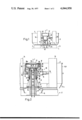
- FIG. 1 shows part of one form of an edge mill according to the invention in elevation with the casing therefor cut away.
- FIG. 2 shows part of the arrangement of FIG. 1 partly in axial section and in an enlarged illustration.
- the edge mill according to the invention in which only one driving motor is necessary which is disposed between the grinding runners on the axis of the track, and the driven member of which is connected directly to the cross head. In this way the driving motor is protected and is easily accessible between the grinding runners.
- the driving transmission from the driving motor to the cross head may be achieved via comparatively short transmission members which may thus be of small dimensions.
- FIGS. 1 and 2 show an edge mill which has an annular disc-like grinding track 2 disposed horizontally around a vertical central axis 1 which is surrounded by a casing 3.
- Casing 3 has a conical section 3a and a cylindrical section 3b connected to the conical section extending as far as the horizontal upper edge 4 of casing 3.
- the grinding track 2 is arranged on a bed or foundation 5, for example, standing on a foundation not shown in detail.
- the bed 5 has a middle or central part 6 coaxial with the central axis 1 for supporting the inner edge of the grinding track 2 as well as an outer annular part 7 (FIG. 1) on which the grinding track 2 rests along the region of its outer periphery.
- a track column 8 Coaxially arranged with the axis 1 there is a track column 8 which has a support section 9 at its lower end by means of which said column 8 is securely fixed by screws 9a to the central part 6 of the bed 5 approximately at the level of the grinding track 2.
- a cross head 10 On the upper end of the track column 8 there is mounted a cross head 10 for rotation about the central axis 1.
- This cross head 10 has two horizontal driver cranks 11, 12 which are connected to the cross head 10.
- the grinding runners 13, 14 are cylindrical with the same diameters, while their axes 15, 16 extend parallelly to the grinding track 2 and are horizontal.
- the grinding runners 13, 14 have different radial distances from the central axis 1 so that one grinding runner 13 reaches as far as the outer periphery and the other grinding runner 14 reaches as far as the inner periphery of the grinding track 2.
- the grinding runners 13, 14 are driven by a drive 17 which is arranged between the grinding runners 13, 14 and is coaxial with the central axis 1.
- the drive 17 has a driving motor 18 in the form of a hydraulic motor so that for the drive connection of the driving motor 18 to the cross head 10 a gear is not necessary, in contrast to heretofore designs of the type involved, and the driven member of the driving motor 18 can be directly rotationally connected and locked to the cross head 10.
- the cross head 10 in its lower part is a cylindrical bearing sleeve 19 which extends approximately over half the height of the track column 8.
- the bearing sleeve 19 is reduced in diameter and surrounds the outer periphery of the column 8 so that in a simple manner a very secure bearing is possible.
- two radial bearings 21, 22 located in axially spaced relationship to each other. These bearings are respectively located in the upper and lower regions of the bearing sleeve 19 while therebetween there are arranged two spacer sleeves 23, 24.
- One of these sleeves engages the inner periphery of the bearing sleeve 19, and the other sleeve engages the outer periphery of the upper end 20 of the track column 8 so that the outer and inner ring of the radial bearings 21, 22 are held spaced apart from one another.
- the flange rings 25, 26 are provided with centering projections or centering collars for engaging the bore of the bearing sleeve having a constant diameter over the entire axial extent of the bearing sleeve 19.
- a clamping ring 27 Connected to the upper end of the track column 8 is a clamping ring 27 by means of which the inner rings of the radial bearings 21, 22 are braced against one another and against the inner spacer sleeve 24.
- the inner ring of the lower radial bearing 22 is supported by an annular shoulder of the track column 8.
- the upper end faces of the annular flange 25 and of the clamping ring 27 are located in a common plane as well as in the plane of the upper end face 28 of the track column 8.
- an axial bearing 29 for the axial supporting of the cross head 10.
- the upper race ring of bearing 29 rests against this flange ring 26.
- the lower race ring by way of a further flange ring 30 rests against the annular shoulder of the track column 8.
- the flange ring 30 has the same diameter as the support section 9 respectively being reduced with outer diameter in respect to the bearing sleeve 19 or having approximately the same outer diameter as an annular collar of the flange ring 26.
- the flange ring 26 surrounds the axial bearing 29 almost as far as the flange ring 30 so that the axial bearing 29 is protected.
- the bearing sleeve 19 On the upper end, the bearing sleeve 19 has a flange disc 31 formed in one piece therewith. In the region of outer periphery of the flange disc there is an annular collar 32.
- the drive 17 is connected to the cross head 10 by way of flange disc 31 or bearing sleeve 19 annular collar 32 of the flange disc 31 supporting a cap member 37 secured by screws 32a, 38a.
- the driving motor 18 has on its bottom side a cylindrical element 33 securely fixed thereto and can thus be fixed in a simple manner and securely onto the upper end of the track column 8.
- the outer cross section of the element 33 corresponds to the cross section of the bore of the track column 8 which is formed as a hollow column so that the drive 17 is accurately aligned in respect of the track column 8.
- an annular collar 34 having a lower annular shoulder by means of which the drive 17 rests against the upper end face 28 of the track column 8.
- the element 33 and the annular collar 34 may be designed in one piece with a lower housing part 35 of the driving motor 18. This housing part 35 forms the stationary part of the drive.
- the driven member 36 of the drive 17 is provided on the upper side of driving motor 18 and is likewise formed by a housing part which upon operation of the mill, rotates relative to the housing part 35.
- the driven member 36 is drivingly connected to the cross head 10 by way of a cap member 37.
- This cap member 37 is separable from the driven member 36 and/or from the cross head 10 and from the flange disc 31 so that simple possibilities of mounting result.
- the cap member 37 formed as a hood has on its upper end an annular disc-shaped section 38 by means of which it surrounds the driven member 36 and is fixed thereto.
- the section 38 merges with a covering section 39 directly downwardly which has its lower end face connected to the upper end of the annular collar 32 by fastening screws 32a.
- the cap member 37 surrounds the drive and fastening screws 38a hold the section 38 of the cap member 37 relative to the driving motor 18 approximately over the entire height in the form of a housing.
- the flange disc 31 forms the lower housing wall so that the drive is safely protected.
- the support section 9 of the track column 8 has vertical supporting ribs 40 distributed uniformly around the periphery with a centering flange 41 on the upper side of the middle part 6 and is centered in the bore of a central sleeve 42 of the middle part 6 so that with simple mounting an accurate alignment is insured.
- connection pipes 43, 44 for the drive motor 18 are guided by the bore of the track column 8 which has a constant diameter over the entire height of column 8.
- the upper ends 45 of the connecting pipes 43, 44 which are parallel to one another, are fixed in a simple manner inside the track column 8 on the underside of the element 33.
- the connecting pipes 43, 44 are guided downwardly by the central sleeve 42 from the bed 5 and in a manner, not shown, are connected to a hydraulic unit which, for example, includes a hydraulic pump driven by means of an electric motor.
- the track column 8 may be screwed onto the bed 5. Furthermore the cap member 37 may be fixed by a screw connection onto the hydraulic motor and onto the cross head.
Landscapes
- Engineering & Computer Science (AREA)
- Food Science & Technology (AREA)
- Crushing And Grinding (AREA)
- Crushing And Pulverization Processes (AREA)
Applications Claiming Priority (2)
| Application Number | Priority Date | Filing Date | Title |
|---|---|---|---|
| DE2438346A DE2438346C3 (de) | 1974-08-09 | 1974-08-09 | Kollergang |
| DT2438346 | 1974-08-09 |
Publications (1)
| Publication Number | Publication Date |
|---|---|
| US4044958A true US4044958A (en) | 1977-08-30 |
Family
ID=5922829
Family Applications (1)
| Application Number | Title | Priority Date | Filing Date |
|---|---|---|---|
| US05/602,654 Expired - Lifetime US4044958A (en) | 1974-08-09 | 1975-08-07 | Edge mill |
Country Status (6)
| Country | Link |
|---|---|
| US (1) | US4044958A (it) |
| DE (1) | DE2438346C3 (it) |
| DK (1) | DK324875A (it) |
| ES (1) | ES440036A1 (it) |
| GB (1) | GB1467567A (it) |
| IT (1) | IT1040498B (it) |
Cited By (2)
| Publication number | Priority date | Publication date | Assignee | Title |
|---|---|---|---|---|
| US6092749A (en) * | 1998-12-03 | 2000-07-25 | Stegmeier; Bill | Dual motor drive system |
| US20140048968A1 (en) * | 2011-04-28 | 2014-02-20 | Ishihara Sangyo Kaisha, Ltd | Method for producing lithium titanate precursor, method for producing lithium titanate, lithium titanate, electrode active material, and electricity storage device |
Citations (3)
| Publication number | Priority date | Publication date | Assignee | Title |
|---|---|---|---|---|
| US792161A (en) * | 1904-08-19 | 1905-06-13 | Wellman Seaver Morgan Co | Chilian mill. |
| US958305A (en) * | 1910-03-11 | 1910-05-17 | Thomas G Plant | Work-holder for heeling-machines. |
| US2461176A (en) * | 1945-06-30 | 1949-02-08 | Pettibone Mulliken Corp | Mulling apparatus |
Family Cites Families (1)
| Publication number | Priority date | Publication date | Assignee | Title |
|---|---|---|---|---|
| DE7242404U (de) * | 1972-11-17 | 1973-03-22 | Rieter Werke | Kollergang |
-
1974
- 1974-08-09 DE DE2438346A patent/DE2438346C3/de not_active Expired
-
1975
- 1975-07-17 DK DK324875A patent/DK324875A/da not_active Application Discontinuation
- 1975-07-31 GB GB3197575A patent/GB1467567A/en not_active Expired
- 1975-08-05 ES ES440036A patent/ES440036A1/es not_active Expired
- 1975-08-05 IT IT26126/75A patent/IT1040498B/it active
- 1975-08-07 US US05/602,654 patent/US4044958A/en not_active Expired - Lifetime
Patent Citations (3)
| Publication number | Priority date | Publication date | Assignee | Title |
|---|---|---|---|---|
| US792161A (en) * | 1904-08-19 | 1905-06-13 | Wellman Seaver Morgan Co | Chilian mill. |
| US958305A (en) * | 1910-03-11 | 1910-05-17 | Thomas G Plant | Work-holder for heeling-machines. |
| US2461176A (en) * | 1945-06-30 | 1949-02-08 | Pettibone Mulliken Corp | Mulling apparatus |
Cited By (3)
| Publication number | Priority date | Publication date | Assignee | Title |
|---|---|---|---|---|
| US6092749A (en) * | 1998-12-03 | 2000-07-25 | Stegmeier; Bill | Dual motor drive system |
| US20140048968A1 (en) * | 2011-04-28 | 2014-02-20 | Ishihara Sangyo Kaisha, Ltd | Method for producing lithium titanate precursor, method for producing lithium titanate, lithium titanate, electrode active material, and electricity storage device |
| US9428396B2 (en) * | 2011-04-28 | 2016-08-30 | Ishihara Sangyo Kaisha, Ltd | Method for producing lithium titanate precursor, method for producing lithium titanate, lithium titanate, electrode active material, and electricity storage device |
Also Published As
| Publication number | Publication date |
|---|---|
| DK324875A (da) | 1976-02-10 |
| ES440036A1 (es) | 1977-02-16 |
| DE2438346A1 (de) | 1976-02-19 |
| IT1040498B (it) | 1979-12-20 |
| DE2438346B2 (de) | 1981-09-03 |
| DE2438346C3 (de) | 1982-05-06 |
| GB1467567A (en) | 1977-03-16 |
Similar Documents
| Publication | Publication Date | Title |
|---|---|---|
| US3518798A (en) | Polishing machine | |
| GB1560388A (en) | Plant having a tube turbine or tube pump | |
| US2359987A (en) | Pedestal type crusher | |
| US3579916A (en) | Polishing machine | |
| US4044958A (en) | Edge mill | |
| KR840001928A (ko) | 데리크 크레인 | |
| US4177610A (en) | Apparatus for machining large heavy workpieces in situs | |
| US2998935A (en) | Grinding-mixing mill for foundry sand | |
| US3515115A (en) | Lapping machine | |
| JPS5879554A (ja) | 改良された駆動手段を有する回転装置 | |
| US4382561A (en) | Vertical roller mill | |
| US5616068A (en) | Method and apparatus for grinding peripheral grooves in rolling mill guide rollers | |
| US5190229A (en) | Rolling bearing arrangement for a conical crusher | |
| US3158333A (en) | Grinding apparatus for fibrous materials | |
| US4270704A (en) | Crusher | |
| FI82392B (fi) | Skivkvarn. | |
| CA1084886A (en) | Gyratory crusher having an eccentric shaft supported by pairs of spaced bearing assesmblies | |
| US4048076A (en) | Center column drive arrangement for circular clarifiers | |
| US3109600A (en) | Gyratory crusher assembly | |
| CN100525918C (zh) | 辊磨机 | |
| US3339852A (en) | Gyroscopic crusher of shallow height | |
| US4026074A (en) | Grinding wheel tubular support for radial expansion thereof | |
| US1957228A (en) | Crusher | |
| USRE19538E (en) | Intercone mill | |
| KR100579078B1 (ko) | 상부 지지형 로터리 테이블 장치 |