US4045088A - Oscillating disk thin seam mining machine with steering - Google Patents
Oscillating disk thin seam mining machine with steering Download PDFInfo
- Publication number
- US4045088A US4045088A US05/676,420 US67642076A US4045088A US 4045088 A US4045088 A US 4045088A US 67642076 A US67642076 A US 67642076A US 4045088 A US4045088 A US 4045088A
- Authority
- US
- United States
- Prior art keywords
- machine
- props
- mining machine
- cylinders
- portions
- Prior art date
- Legal status (The legal status is an assumption and is not a legal conclusion. Google has not performed a legal analysis and makes no representation as to the accuracy of the status listed.)
- Expired - Lifetime
Links
Images
Classifications
-
- E—FIXED CONSTRUCTIONS
- E21—EARTH OR ROCK DRILLING; MINING
- E21C—MINING OR QUARRYING
- E21C31/00—Driving means incorporated in machines for slitting or completely freeing the mineral from the seam
- E21C31/02—Driving means incorporated in machines for slitting or completely freeing the mineral from the seam for cutting or breaking-down devices
- E21C31/04—Driving means incorporated in machines for slitting or completely freeing the mineral from the seam for cutting or breaking-down devices imparting both a rotary and reciprocating motion
-
- E—FIXED CONSTRUCTIONS
- E21—EARTH OR ROCK DRILLING; MINING
- E21C—MINING OR QUARRYING
- E21C25/00—Cutting machines, i.e. for making slits approximately parallel or perpendicular to the seam
- E21C25/20—Machines slitting solely by one or more reciprocating sawing implements or reciprocating cutter chains; Shaker conveyors with cutting means
-
- E—FIXED CONSTRUCTIONS
- E21—EARTH OR ROCK DRILLING; MINING
- E21D—SHAFTS; TUNNELS; GALLERIES; LARGE UNDERGROUND CHAMBERS
- E21D9/00—Tunnels or galleries, with or without linings; Methods or apparatus for making thereof; Layout of tunnels or galleries
- E21D9/10—Making by using boring or cutting machines
- E21D9/1006—Making by using boring or cutting machines with rotary cutting tools
- E21D9/1013—Making by using boring or cutting machines with rotary cutting tools on a tool-carrier supported by a movable boom
Definitions
- the invention relates to a mining machine and a method for mining of minerals, in particular of ores of non-ferrous metals, of thin bands of reef layers in hard rock.
- the working cavity support generally is a wooden structure, in exceptional cases a steel construction, and in any case in the known manner this is extremely expensive regarding material, time and labour.
- the invention intends to provide a relief.
- Tunnel drilling machines also are known with at least one drilling head pivotable about a horizontal pivoting axis for arcuate drilling out of a tunnel space and with a carriage with front part and rear part joined by thrust cylinders and being supportable against the slot space walls by means of hydraulic props.
- Such tunnel drilling machines are not practical for use as mining machines, if the mining of minerals has to take place from thin layers.
- the known tunnel drilling machines are relatively high and wide and are almost unsuitable for excavating only narrow bands of reef layers of minerals in hard rock. In any case, the application for such purposes is uneconomic.
- Another method of excavating thin layers of ore known under the name of ⁇ slot drilling ⁇ is carried out by drilling a row of parallel, cylindrical holes into the reef, leaving a narrow bridge of ore untouched between two adjacent holes as support for the overlaying rock. In this way it is not possible to excavate the ore layer completely.
- the invention has as object to provide a mining machine, in particular a slot drilling machine, which simplifies the mining of minerals, in particular of ores of non-ferrous metals, from bands of reef layers and for this purpose is provided as a particularly compact, flat and adaptable construction with great manoeuvrability and relatively low weight.
- a mining machine in particular a slot drilling machine is proposed with at least one drilling head pivotable about a vertical pivoting axis for arcuate drilling of a slot cavity and with a carriage comprising a front part and a rear part joined by thrust cylinders and hydraulic props supportable against the slot cavity wall, the bore head has at least one oscillation disc segment armed with one or more drilling tools with at least one operation cylinder engaging eccentrically to it and this oscillation disc segment is supported oscillatingly in horizontal position about the vertical pivoting axis.
- a mechanically relatively simple design of a drilling head is achieved, which is characterized by extreme freedom of movement and which can cut into the full reef as well as work continuously along a stoping face.
- the drilling head can be extremely flat, because the drilling tools are carried by a single oscillating disc segment in such a way, that they cut a slot, which is slightly higher than the machine-body.
- several oscillation disc segments are arranged side by side, and/or one above the other, and/or displaced to each other in travelling direction.
- the oscillation disc segment is fitted with conventional or vibrating roller bits as drilling tools.
- Roller bits are particularly suitable for drilling out or breaking out hard rock.
- respectively at least two roller bits are arranged displaced in height to each other and with their roller axes inclined to each other in vertical orientation with the formation of a V-shaped or circular or other shaped drilling line in vertical projection plane as well as exceeding the height of the machine-body. Consequently the total mining machine in accordance with the invention is flatter than the height of the roller bits and therefore is characterized in particular by its compact construction. It therefore is suitable for application as slot drilling machine in places where reef mineral layers of lesser thickness are to be mined from hard rock.
- Adaptability and extreme manoeuvrability of the slot drilling machine according to this invention is obtained by the fact that the front part and the rear part of the carriage are formed as rockers, suspended pivotable or linked on both sides to the hydraulic props which are supported against the foot wall and hanging wall.
- a slide with the oscillation disc segment mounted thereto, while in the rear part at least one thrust cylinder acts against the slide.
- two thrust cylinders are provided in the rear part axial-symmetrically next to each other, which are connected to the carriage in rigid manner or by way of a link-connection.
- the thrust cylinders can be mounted in guide bushes joined to the slide.
- two operating cylinders are mounted on the slide axial-symmetrically next to each other and being pivotable about a vertical pivoting axis and engage diametrally to the oscillation disc segment.
- the oscillation disc segment is mounted to oscillate to and fro on a slide, which can move in a traverse.
- This traverse is supported on both sides by hydraulic props, which can be joined to a third hydraulic prop by means of thrust cylinders with formation of a three-point support.
- the third hydraulic prop can be joined by means of a thrust cylinder to the centre of the slide.
- the invention further suggests that two operating cylinders, which are joined to the slide, engage symmetrically to the oscillation disc segment.
- Two or more oscillation disc segments can be arranged on the slide either side by side, and/or above another and/or displaced in travelling direction.
- the invention also relates to a method for mining of minerals, in particular of ores of non-ferrous metals, from narrow reef layers in hard rock by means of a mining machine in accordance with the invention, which is characterized thereby that initially the mineral containing layer is drilled out or cut out from its exposed face side on a wide front in layer height and in given depth from the rock, and thereafter the slot cavity so formed can be widened to a full working height by a similar machine and this working cavity is supported by means of support props provided between foot and hanging walls, using rock received from the working cavity in comparatively small pieces to form with the addition of a cement/water mixture concrete-support props.
- the mineral containing layer to be mined is not opened first and is then broken out from between the upper and lower slots by hand, but the layer is taken out directly so that the created slot cavity can be mined mechanically and can then be widened into a working cavity without taking care of the mineral containing layer, which has been removed before.
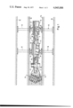
- FIG. 1 in schematic representation a mining machine, in particular a slot drilling machine, in accordance with the invention and shown during use (in side view);
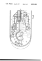
- FIG. 2 the machine of FIG. 1 seen from above;
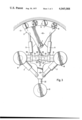
- FIG. 3 a further variation of the machine according to FIG. 1 in plan view from above.
- a mining machine in particular a slot drilling machine, is illustrated, which in its basic construction consists of a drilling head 2, which is pivotable about a vertical pivoting axis 1 and which is used for arcuate drilling out of a slot cavity 3, further a carrier 4 comprising a front part 5 and a rear part 6 both joined by thrust cylinders 7 and hydraulic props 8 supportable against upper and lower slot cavity wall.
- the drilling head 2 has at least one oscillating disc segment 10 armed with at least two or preferably more drilling tools 9 and provided with at least one eccentrically engaging operation cylinder 11.
- the oscillating disc segment 10 is suspended at the front part 5 of the carrier 4 to oscillate in a horizontal plan about the vertical pivoting axis 1. If the oscillation disc segment 10 is operated with only one single engaging operation cylinder 11, then this cylinder is provided as double acting cylinder. If it is ncessary to excavate over a relatively wide front, then several oscillating disc segments 10 can be arranged next to each other and staggered in travelling direction. In the shown and preferred embodiment each oscillation disc segment 10 is armed with roller bits as drilling tools 9. According to FIG. 1 two roller bits are staggered in vertical direction relatively to each other and in vertical orientation to each other at inclined roller axes 12 with the consequent formation of a V-shaped, circular or other drilling line in vertical projection plane.
- the roller bits arranged in this manner thereby exceed the height of the machine-body, so that it can follow the excavation development even when mining minerals from reef layers of particularly thin thickness.
- the front part 5 and the rear part 6 of the carrier 4 are formed as rockers, which are suspended pivotably about a horizontal pivoting axis 13 or which are link-connected on both sides to the hydraulic props 8, which are supported against the lower or foot wall 14 and the upper or hanging wall 15.
- Preferably three or four hydraulic props 8 are provided in axial-symmetrical arrangement on both sides of the carrier 4, so that the slot drilling machine can move and drill not only forwardly and rearwardly, but also in an extremely arcuate manner to the right or the left.
- two operation cylinders 11 are mounted axial-symmetrically side by side so as to be pivotable about vertical pivoting axes 19 and engage diametrally with the oscillation disc segment 10.
- the operation cylinders 11 can be provided as single acting cylinders.
- the oscillation disc segment 10 is mounted on a slide 23 to oscillate to and fro.
- the traverse 20 is supported on both sides by the hydraulic props 8, which are connected to a third hydraulic prop 21 by means of the thrust cylinder 7 with the formation of a three-point support.
- the third hydraulic prop 21 is to be connected additionally to the rear end of the slide 23 by means of a thrust cylinder 22.
- a continuous operation of the machine is possible, that means, interruptions are only required for switching the hydraulics.
- the thrust and operation cylinders 7, 11, 22 are mounted so as to be link-connected.
- the connection of the drilling tools 9 to the oscillating disc segment or segments 10 as well as the hydraulic installation are not shown. In the construction of FIG. 3 impact tools 9 are used.
- Machines according to the invention can be used to widen the slot by lengthening the hydraulic props on the lower or upper side. But this is also possible by moving the machine-body upwards or downwards within the maximum stroke of the prop-cylinders.
- the mining machine in accordance with the invention is characterized by the fact, that it can excavate by alternating cooperation with the thrust cylinders 7 or 22 and the hydraulic props 8 or 21 in each desired working direction and by turning on the spot about a vertical rotational axis through more than 180°, and also by working without resulting bridge or step formations.
- the drilling tools 9, in accordance with the invention are roller, impact or cutting drilling tools, in particular formed as conventional or impact roller bits, impact hammers, beams or jet cutters, or any other suitable cutters. By means of these drilling tools 9 the mining machine can be fitted individually or in combination with different cutter types.
- the three hydraulic props 8, 8 and 21 are supported against the lower or foot wall and the upper or hanging wall.
- the disc segment head 10 with the tools 9 mounted thereto can be oscillated to one side and to the other, respectively by means of correspondingly engaging operating cylinders 11.
- those tools 9 are impact tools because roller bits as drilling tools would demand a slightly differing construction permitting the disc segment 10 to be moved in a similar way as disclosed in connection with FIG. 2.
- the slide 23 is continuously pressed ahead by the operating cylinder 22 which is supporting against the hydraulic prop 21 wherein the thrust cylinders 7 alternatively can be set pressureless or can assist such an advancing movement by corresponding pressure admission. Slide 23 then moves against the traverse 20 guided by a pin or stud 26 which in turn slides in a slot 27 of slide 23.
- traverse 20 further comprises a block-like sliding element 28 slidably mounted for sliding movement within traverse 20 by means of alternatively engaging operating cylinders 24 and 25.
- slide 23 is engaged and taken along so that slide 23 can be pivoted around the axis of the hydraulic prop 21 which in turn is pivotally mounted for pivotal movement around her axis as well as are the hydraulic props 8.
- this embodiment is giving permission to traverse 20 to be guided by socket formed or bushing like adjoint pieces 30 and 31 mounted to the hydraulic props 8 whereby the corresponding hydraulic props can be moved aside when one of the hydraulic props 8 has been released and when the corresponding thrust cylinder 7 has been set pressureless.
- the machine according to this invention can be installed completely or partly in a shield, a box or the like, in which case the thrust for the drilling tools can be excerted from behind over the shield, the box or the like.
- the shield, the box or the like covers the drilling head to an appreciable extent and serves simultaneously as a guide, so that additional clamping devices can be omitted.
- the widening of the slot can be carried out not only in the manner described above, but also by the addition of special widening tools, which can be swung out, pushed out or the like and, for emergency cases, may be arranged to drill in rearward direction.
Landscapes
- Engineering & Computer Science (AREA)
- Mining & Mineral Resources (AREA)
- Life Sciences & Earth Sciences (AREA)
- General Life Sciences & Earth Sciences (AREA)
- Geochemistry & Mineralogy (AREA)
- Geology (AREA)
- Mechanical Engineering (AREA)
- Environmental & Geological Engineering (AREA)
- Earth Drilling (AREA)
- Drilling And Exploitation, And Mining Machines And Methods (AREA)
Applications Claiming Priority (6)
| Application Number | Priority Date | Filing Date | Title |
|---|---|---|---|
| ZA752446 | 1975-04-17 | ||
| ZA75/2446 | 1975-04-17 | ||
| ZA756189 | 1975-09-29 | ||
| ZA75/6187 | 1975-09-29 | ||
| ZA75/6189 | 1975-09-29 | ||
| ZA756187A ZA756187B (en) | 1975-09-30 | 1975-09-30 | Drilling method and apparatus |
Publications (1)
| Publication Number | Publication Date |
|---|---|
| US4045088A true US4045088A (en) | 1977-08-30 |
Family
ID=27420872
Family Applications (1)
| Application Number | Title | Priority Date | Filing Date |
|---|---|---|---|
| US05/676,420 Expired - Lifetime US4045088A (en) | 1975-04-17 | 1976-04-13 | Oscillating disk thin seam mining machine with steering |
Country Status (8)
| Country | Link |
|---|---|
| US (1) | US4045088A (de) |
| AT (1) | ATA284976A (de) |
| AU (1) | AU1310076A (de) |
| CA (1) | CA1033373A (de) |
| DE (1) | DE2616904A1 (de) |
| FR (1) | FR2307950A1 (de) |
| GB (1) | GB1520984A (de) |
| SE (1) | SE7604450L (de) |
Cited By (25)
| Publication number | Priority date | Publication date | Assignee | Title |
|---|---|---|---|---|
| WO1980001188A1 (en) * | 1978-12-11 | 1980-06-12 | R Livesay | Mechanically actuated impact mechanism |
| US4247149A (en) * | 1978-12-11 | 1981-01-27 | Caterpillar Tractor Co. | Mechanically actuated impact mechanism |
| US4265565A (en) * | 1977-09-24 | 1981-05-05 | Gewerkschaft Eisenhutte Westfalia | Tunnel drive shield |
| EP0066156A1 (de) * | 1981-05-20 | 1982-12-08 | Oy Tampella Ab | Verfahren zum Auffahren eines Tunnels im Gestein mit Hilfe einer Gesteinsbohrmaschine |
| US4371211A (en) * | 1980-12-11 | 1983-02-01 | Jarva, Inc. | Tunnel boring machine and method of operating same |
| WO1985002653A1 (en) * | 1983-12-06 | 1985-06-20 | The Robbins Company | Mobile mining machine and method |
| US5190407A (en) * | 1991-01-14 | 1993-03-02 | Kabushiki Kaisha Iseki Kaihatsu Koki | Rectangular shield excavating machine |
| US5192116A (en) * | 1991-05-28 | 1993-03-09 | The Robbins Company | Gantry-type mobile mining machine |
| US5192115A (en) * | 1991-05-28 | 1993-03-09 | The Robbins Company | Tramming mobile mining machine |
| US5234257A (en) * | 1991-10-11 | 1993-08-10 | The Robbins Company | Mobile mining machine having tilted swing axis and method |
| US5538362A (en) * | 1992-10-08 | 1996-07-23 | Kabushiki Kaisha Iseki Kaihatsu Koki | Shield excavator |
| WO2002001045A1 (de) * | 2000-06-28 | 2002-01-03 | Voest-Alpine Bergtechnik Gesellschaft M.B.H. | Vortriebs- oder gewinnungsmaschine für den abbau von gestein |
| US20030173819A1 (en) * | 2001-12-10 | 2003-09-18 | Hames Marilyn Patricia Ann | Mining method for steeply dipping ore bodies |
| US20040207247A1 (en) * | 2002-10-15 | 2004-10-21 | Eric Jackson | Automated excavation machine |
| WO2005049965A1 (en) * | 2003-11-21 | 2005-06-02 | Atlas Copco Rock Drills Ab | Boring rig |
| US20060000121A1 (en) * | 2004-04-23 | 2006-01-05 | Placer Dome Technical Services Limited | Excavation apparatus and method |
| US20060225308A1 (en) * | 2005-03-18 | 2006-10-12 | Maximilian Arzberger | Foundation construction device for making trenches in soil |
| WO2008089509A1 (en) * | 2007-01-25 | 2008-07-31 | Cmte Development Limited | Rock sampling apparatus |
| WO2011093777A1 (en) * | 2010-01-26 | 2011-08-04 | Atlas Copco Craelius Ab | Method and device for working rock |
| WO2013020068A1 (en) * | 2011-08-03 | 2013-02-07 | Joy Mm Delaware, Inc. | Stabilization system for a mining machine |
| CN103485776A (zh) * | 2013-10-16 | 2014-01-01 | 太仓市高泰机械有限公司 | 一种多功能的采煤机的振动机构 |
| US20150152728A1 (en) * | 2011-09-27 | 2015-06-04 | Sverker Hartwig | Device And Method For Driving Tunnels, Galleries Or The Like |
| CN110735647A (zh) * | 2019-11-05 | 2020-01-31 | 中国矿业大学 | 不影响支护作业且可按预定路径破岩的偏心滚刀式掘进机 |
| CN114263472A (zh) * | 2021-11-13 | 2022-04-01 | 中国煤炭科工集团太原研究院有限公司 | 一种煤矿拱形断面连续截割方法 |
| RU2777772C1 (ru) * | 2019-11-05 | 2022-08-09 | Чайна Юниверсити Оф Майнинг Энд Текнолоджи | Проходческий комбайн с эксцентриковой фрезой, способный разрушать горную породу по заданной траектории, не влияя при этом на операцию поддержки |
Families Citing this family (4)
| Publication number | Priority date | Publication date | Assignee | Title |
|---|---|---|---|---|
| DE3343120C1 (de) * | 1983-11-29 | 1985-03-28 | Mannesmann AG, 4000 Düsseldorf | Tunnelvortriebsmaschine mit einem mit Schneidwerkzeugen bestückten, durch einen Antrieb bewegten Werkzeugträger |
| HUT51731A (en) * | 1988-11-10 | 1990-05-28 | Veszpremi Szenbanyak Vallalat | Cutting disc for breaking coal |
| AU654487B2 (en) * | 1990-05-17 | 1994-11-10 | Z C Mines Pty. Ltd. | Mobile continuous mining machine |
| US5205612A (en) * | 1990-05-17 | 1993-04-27 | Z C Mines Pty. Ltd. | Transport apparatus and method of forming same |
Citations (6)
| Publication number | Priority date | Publication date | Assignee | Title |
|---|---|---|---|---|
| US2840271A (en) * | 1956-09-07 | 1958-06-24 | Modern Tool & Die Company | Seed and fertilizer spreader |
| DE2034210A1 (de) * | 1970-07-10 | 1972-02-03 | Schönfeld, Georg, 2200 Elmshorn | Verfahren und Maschine zum mechanischen Auffahren von Tunnel und Strecken im Bergbau |
| US3647263A (en) * | 1970-03-19 | 1972-03-07 | Atlas Copco Ab | Tunnelling machines and the like |
| US3647264A (en) * | 1970-04-14 | 1972-03-07 | Atlas Copco Ab | Machine for driving tunnels, drifts, raises, and the like |
| US3663054A (en) * | 1969-03-25 | 1972-05-16 | Michel A Dubois | Machine for digging underground galleries |
| DE2064617A1 (de) * | 1970-12-30 | 1972-07-20 | Ruhrkohle Ag, 4300 Essen | Verfahren und Anordnung zum Erstellen von Abschlußdämmen für abgeworfene Grubenbaue |
Family Cites Families (3)
| Publication number | Priority date | Publication date | Assignee | Title |
|---|---|---|---|---|
| DE445207C (de) * | 1924-10-16 | 1927-06-04 | Carl Brozeit Sen | Schraemwerkzeug mit schwingbar gelagerter Saege |
| DE2127186A1 (de) * | 1971-06-01 | 1972-12-14 | Schönfeld, Georg, 2200 Elmshorn | Verfahren und Vorrichtung zum mechanischen Auffahren von Tunnel und Strecken im Bergbau |
| LU68283A1 (de) * | 1973-08-22 | 1975-05-21 |
-
1976
- 1976-04-12 CA CA250,020A patent/CA1033373A/en not_active Expired
- 1976-04-12 GB GB14786/76A patent/GB1520984A/en not_active Expired
- 1976-04-13 US US05/676,420 patent/US4045088A/en not_active Expired - Lifetime
- 1976-04-14 SE SE7604450A patent/SE7604450L/xx unknown
- 1976-04-15 DE DE19762616904 patent/DE2616904A1/de not_active Ceased
- 1976-04-15 AU AU13100/76A patent/AU1310076A/en not_active Expired
- 1976-04-16 FR FR7611368A patent/FR2307950A1/fr not_active Withdrawn
- 1976-04-16 AT AT284976A patent/ATA284976A/de not_active Application Discontinuation
Patent Citations (6)
| Publication number | Priority date | Publication date | Assignee | Title |
|---|---|---|---|---|
| US2840271A (en) * | 1956-09-07 | 1958-06-24 | Modern Tool & Die Company | Seed and fertilizer spreader |
| US3663054A (en) * | 1969-03-25 | 1972-05-16 | Michel A Dubois | Machine for digging underground galleries |
| US3647263A (en) * | 1970-03-19 | 1972-03-07 | Atlas Copco Ab | Tunnelling machines and the like |
| US3647264A (en) * | 1970-04-14 | 1972-03-07 | Atlas Copco Ab | Machine for driving tunnels, drifts, raises, and the like |
| DE2034210A1 (de) * | 1970-07-10 | 1972-02-03 | Schönfeld, Georg, 2200 Elmshorn | Verfahren und Maschine zum mechanischen Auffahren von Tunnel und Strecken im Bergbau |
| DE2064617A1 (de) * | 1970-12-30 | 1972-07-20 | Ruhrkohle Ag, 4300 Essen | Verfahren und Anordnung zum Erstellen von Abschlußdämmen für abgeworfene Grubenbaue |
Cited By (54)
| Publication number | Priority date | Publication date | Assignee | Title |
|---|---|---|---|---|
| US4265565A (en) * | 1977-09-24 | 1981-05-05 | Gewerkschaft Eisenhutte Westfalia | Tunnel drive shield |
| WO1980001188A1 (en) * | 1978-12-11 | 1980-06-12 | R Livesay | Mechanically actuated impact mechanism |
| US4247149A (en) * | 1978-12-11 | 1981-01-27 | Caterpillar Tractor Co. | Mechanically actuated impact mechanism |
| US4371211A (en) * | 1980-12-11 | 1983-02-01 | Jarva, Inc. | Tunnel boring machine and method of operating same |
| EP0066156A1 (de) * | 1981-05-20 | 1982-12-08 | Oy Tampella Ab | Verfahren zum Auffahren eines Tunnels im Gestein mit Hilfe einer Gesteinsbohrmaschine |
| US4548442A (en) * | 1983-12-06 | 1985-10-22 | The Robbins Company | Mobile mining machine and method |
| WO1985002653A1 (en) * | 1983-12-06 | 1985-06-20 | The Robbins Company | Mobile mining machine and method |
| US5190407A (en) * | 1991-01-14 | 1993-03-02 | Kabushiki Kaisha Iseki Kaihatsu Koki | Rectangular shield excavating machine |
| US5192116A (en) * | 1991-05-28 | 1993-03-09 | The Robbins Company | Gantry-type mobile mining machine |
| US5192115A (en) * | 1991-05-28 | 1993-03-09 | The Robbins Company | Tramming mobile mining machine |
| US5234257A (en) * | 1991-10-11 | 1993-08-10 | The Robbins Company | Mobile mining machine having tilted swing axis and method |
| US5538362A (en) * | 1992-10-08 | 1996-07-23 | Kabushiki Kaisha Iseki Kaihatsu Koki | Shield excavator |
| WO2002001045A1 (de) * | 2000-06-28 | 2002-01-03 | Voest-Alpine Bergtechnik Gesellschaft M.B.H. | Vortriebs- oder gewinnungsmaschine für den abbau von gestein |
| US6857706B2 (en) | 2001-12-10 | 2005-02-22 | Placer Dome Technical Services Limited | Mining method for steeply dipping ore bodies |
| US20030173819A1 (en) * | 2001-12-10 | 2003-09-18 | Hames Marilyn Patricia Ann | Mining method for steeply dipping ore bodies |
| US20100109417A1 (en) * | 2002-10-15 | 2010-05-06 | Minister Of Natural Resources Canada | Automated Excavation Machine |
| US20040207247A1 (en) * | 2002-10-15 | 2004-10-21 | Eric Jackson | Automated excavation machine |
| US8016363B2 (en) | 2002-10-15 | 2011-09-13 | Eric Jackson | Automated excavation machine |
| US7695071B2 (en) | 2002-10-15 | 2010-04-13 | Minister Of Natural Resources | Automated excavation machine |
| US20070035172A1 (en) * | 2003-11-21 | 2007-02-15 | Sverker Hartwig | Boring rig |
| US7357458B2 (en) | 2003-11-21 | 2008-04-15 | Atlas Copco Rock Drills Ab | Boring rig |
| WO2005049965A1 (en) * | 2003-11-21 | 2005-06-02 | Atlas Copco Rock Drills Ab | Boring rig |
| AU2004291822B2 (en) * | 2003-11-21 | 2009-10-29 | Atlas Copco Rock Drills Ab | Boring rig |
| US20060000121A1 (en) * | 2004-04-23 | 2006-01-05 | Placer Dome Technical Services Limited | Excavation apparatus and method |
| US7192093B2 (en) | 2004-04-23 | 2007-03-20 | Placer Dome Technical Services Limited | Excavation apparatus and method |
| US20060225308A1 (en) * | 2005-03-18 | 2006-10-12 | Maximilian Arzberger | Foundation construction device for making trenches in soil |
| US7637038B2 (en) * | 2005-03-18 | 2009-12-29 | Bauer Maschinen Gmbh | Foundation construction device for making trenches in soil |
| US8672417B2 (en) | 2007-01-25 | 2014-03-18 | Cmte Development Limited | Rock sampling apparatus |
| US20090322142A1 (en) * | 2007-01-25 | 2009-12-31 | Cmte Development Limited | Rock sampling apparatus |
| CN101663461B (zh) * | 2007-01-25 | 2012-12-05 | Cmte开发有限公司 | 岩石取样设备 |
| WO2008089509A1 (en) * | 2007-01-25 | 2008-07-31 | Cmte Development Limited | Rock sampling apparatus |
| US8950823B2 (en) | 2010-01-26 | 2015-02-10 | Atlas Copco Craelius Ab | Method and device for working rock |
| CN102725480A (zh) * | 2010-01-26 | 2012-10-10 | 阿特拉斯科普柯克雷柳斯有限公司 | 用于对岩石进行作业的方法及设备 |
| WO2011093777A1 (en) * | 2010-01-26 | 2011-08-04 | Atlas Copco Craelius Ab | Method and device for working rock |
| CN102725480B (zh) * | 2010-01-26 | 2015-05-13 | 阿特拉斯科普柯克雷柳斯有限公司 | 用于对岩石进行作业的方法及设备 |
| AU2017203063B2 (en) * | 2011-08-03 | 2018-09-13 | Joy Global Underground Mining Llc | Stabilization system for a mining machine |
| WO2013020068A1 (en) * | 2011-08-03 | 2013-02-07 | Joy Mm Delaware, Inc. | Stabilization system for a mining machine |
| US8979209B2 (en) | 2011-08-03 | 2015-03-17 | Joy Mm Delaware, Inc. | Stabilization system for a mining machine |
| AU2021200006B2 (en) * | 2011-08-03 | 2022-11-17 | Joy Global Underground Mining Llc | Stabilization system for a mining machine |
| US10316659B2 (en) | 2011-08-03 | 2019-06-11 | Joy Global Underground Mining Llc | Stabilization system for a mining machine |
| CN103827443A (zh) * | 2011-08-03 | 2014-05-28 | 乔伊·姆·特拉华公司 | 采掘机的稳定系统 |
| AU2012289920B2 (en) * | 2011-08-03 | 2017-02-09 | Joy Global Underground Mining Llc | Stabilization system for a mining machine |
| RU2618005C2 (ru) * | 2011-08-03 | 2017-05-02 | ДЖОЙ ЭмЭм ДЕЛАВЭР, ИНК. | Система стабилизации для горной машины |
| US9670776B2 (en) | 2011-08-03 | 2017-06-06 | Joy Mm Delaware, Inc. | Stabilization system for a mining machine |
| CN103827443B (zh) * | 2011-08-03 | 2017-08-11 | 乔伊·姆·特拉华公司 | 采掘机的稳定系统 |
| US9951615B2 (en) | 2011-08-03 | 2018-04-24 | Joy Mm Delaware, Inc. | Stabilization system for a mining machine |
| US9212552B2 (en) * | 2011-09-27 | 2015-12-15 | Atlas Copco Rock Drills Ab | Device and method for driving tunnels, galleries or the like |
| US20150152728A1 (en) * | 2011-09-27 | 2015-06-04 | Sverker Hartwig | Device And Method For Driving Tunnels, Galleries Or The Like |
| CN103485776A (zh) * | 2013-10-16 | 2014-01-01 | 太仓市高泰机械有限公司 | 一种多功能的采煤机的振动机构 |
| CN110735647A (zh) * | 2019-11-05 | 2020-01-31 | 中国矿业大学 | 不影响支护作业且可按预定路径破岩的偏心滚刀式掘进机 |
| CN110735647B (zh) * | 2019-11-05 | 2020-09-01 | 中国矿业大学 | 不影响支护作业且可按预定路径破岩的偏心滚刀式掘进机 |
| RU2777772C1 (ru) * | 2019-11-05 | 2022-08-09 | Чайна Юниверсити Оф Майнинг Энд Текнолоджи | Проходческий комбайн с эксцентриковой фрезой, способный разрушать горную породу по заданной траектории, не влияя при этом на операцию поддержки |
| CN114263472A (zh) * | 2021-11-13 | 2022-04-01 | 中国煤炭科工集团太原研究院有限公司 | 一种煤矿拱形断面连续截割方法 |
| CN114263472B (zh) * | 2021-11-13 | 2024-02-06 | 中国煤炭科工集团太原研究院有限公司 | 一种煤矿拱形断面连续截割方法 |
Also Published As
| Publication number | Publication date |
|---|---|
| SE7604450L (sv) | 1976-10-18 |
| AU1310076A (en) | 1977-10-20 |
| ATA284976A (de) | 1978-05-15 |
| CA1033373A (en) | 1978-06-20 |
| GB1520984A (en) | 1978-08-09 |
| FR2307950A1 (fr) | 1976-11-12 |
| DE2616904A1 (de) | 1977-10-06 |
Similar Documents
| Publication | Publication Date | Title |
|---|---|---|
| US3357742A (en) | Mining arrangement including angularly displaceable guide means for a mining machine | |
| CN1053256C (zh) | 地下开采用的开采设备 | |
| US3647263A (en) | Tunnelling machines and the like | |
| CA2561803C (en) | Mining apparatus with precision navigation system | |
| US3963080A (en) | Tunneling machine for boring a side drift | |
| US4838615A (en) | Apparatus for excavating a recess | |
| US3966258A (en) | Mining boom linkage for separate sump and swing cutting | |
| US4080000A (en) | Tunnelling machine | |
| US4149604A (en) | Mining equipment | |
| CN116677400A (zh) | 一种硬岩掘进机 | |
| US4101173A (en) | Roof prop and platform movably mounted on boom of tunnelling machine | |
| US4095436A (en) | Method of, and apparatus for, controlling the advance of a tunnel drive shield | |
| US4749194A (en) | Sectional cutting machine used to cut curved gallery cross-sections true to profile | |
| RU2130121C1 (ru) | Крепь агрегатная (варианты) | |
| CN110552391A (zh) | 开槽装置 | |
| US3979151A (en) | Rock excavating arched tunnel forming machine | |
| EP1685309B1 (de) | Bohrgestell | |
| CN210917529U (zh) | 开槽装置 | |
| US3776595A (en) | Tunneling machine having access passageway and invert cleaner | |
| RU2011753C1 (ru) | Рабочий орган бульдозера | |
| US4220371A (en) | Method of mineral mining plough operation in two directions of varying depth cut | |
| US2980409A (en) | Coal cutting, drilling, and loading machine | |
| SU901540A1 (ru) | Щит дл проходки тоннелей | |
| SU1208142A1 (ru) | Длиннобазовый планировщик-профилировщик | |
| SU1243634A3 (ru) | Щит дл проходки выемочных штреков подземных добычных забоев |