EP1685309B1 - Bohrgestell - Google Patents
Bohrgestell Download PDFInfo
- Publication number
- EP1685309B1 EP1685309B1 EP04800344A EP04800344A EP1685309B1 EP 1685309 B1 EP1685309 B1 EP 1685309B1 EP 04800344 A EP04800344 A EP 04800344A EP 04800344 A EP04800344 A EP 04800344A EP 1685309 B1 EP1685309 B1 EP 1685309B1
- Authority
- EP
- European Patent Office
- Prior art keywords
- boring
- substructure
- unit
- rig according
- stabilizing means
- Prior art date
- Legal status (The legal status is an assumption and is not a legal conclusion. Google has not performed a legal analysis and makes no representation as to the accuracy of the status listed.)
- Expired - Lifetime
Links
- 230000000087 stabilizing effect Effects 0.000 claims abstract description 41
- 239000011435 rock Substances 0.000 claims abstract description 16
- 238000005304 joining Methods 0.000 claims description 2
- 239000002184 metal Substances 0.000 claims 1
- 230000015572 biosynthetic process Effects 0.000 description 7
- 238000005755 formation reaction Methods 0.000 description 7
- 238000005553 drilling Methods 0.000 description 5
- 238000000034 method Methods 0.000 description 3
- 230000005540 biological transmission Effects 0.000 description 2
- 238000004519 manufacturing process Methods 0.000 description 2
- 238000005065 mining Methods 0.000 description 2
- 230000006641 stabilisation Effects 0.000 description 2
- 238000011105 stabilization Methods 0.000 description 2
- 238000010276 construction Methods 0.000 description 1
- 238000005520 cutting process Methods 0.000 description 1
- 239000000463 material Substances 0.000 description 1
- 238000003825 pressing Methods 0.000 description 1
- 230000001141 propulsive effect Effects 0.000 description 1
- 238000000926 separation method Methods 0.000 description 1
- 238000005728 strengthening Methods 0.000 description 1
Images


Classifications
-
- E—FIXED CONSTRUCTIONS
- E21—EARTH OR ROCK DRILLING; MINING
- E21C—MINING OR QUARRYING
- E21C25/00—Cutting machines, i.e. for making slits approximately parallel or perpendicular to the seam
- E21C25/58—Machines slitting by drilling hole on hole
-
- E—FIXED CONSTRUCTIONS
- E21—EARTH OR ROCK DRILLING; MINING
- E21C—MINING OR QUARRYING
- E21C35/00—Details of, or accessories for, machines for slitting or completely freeing the mineral from the seam, not provided for in groups E21C25/00 - E21C33/00, E21C37/00 or E21C39/00
- E21C35/06—Equipment for positioning the whole machine in relation to its sub-structure
Definitions
- the present invention concerns a boring rig according to the preamble of the independent claim.
- boring rigs for underground boring wherein a carrier vehicle at an end position carries a launching device which is pivotal in a plane parallel to a general travel direction of the boring rig with respect to the substructure of the boring rig.
- a boring unit is extendable from a position inside the launching device axially by means of cutter head rotation and forcing means in order to provide the boring operation.
- a boring rig according to the background art is intended and functions well for underground operation, but is time-consuming to set up and its usefulness for production boring is limited in specific applications.
- US-2 726 064 describes a drilling and conveying apparatus having levelling floor jacks and rearward abutment jacks.
- GB 800 864 describes a mining machine comprising a propulsion unit which travels along a mine gate.
- US-3 167 344 representing the closest prior art as described in the preamble of claim 1, relates to mining very thin on bodies.
- Such ore is often present in very large shallow cup-shaped formations whereby excavating the ore is carried out in directions relatively close to the horizontal. For that reason the boring unit is pivotal for operation in directions sideways from the travel direction of the boring rig and pivotal in a plane perpendicular to that direction.
- the boring unit is pivotal over an angle of about 10° below the horizontal to an angle of about 30° above the horizontal.
- each rotation joint there is a force transmitting means provided between each rotation joint and an adjacent holder for a horizontal jack.
- forces occurring during boring are transmitted and resisted in an effective way.
- each holder for a horizontal jack is integral with a stationary part of a respective pivot means.
- the boring unit including a front and a rear frame portion which are separated by linear guide means for guiding bore string rotation and forcing means, an effective, stable and cost effective boring unit is provided.
- the boring unit is pivotally attached to the substructure over its rear frame portion because of stability and the possibility of having a compact solution.
- the boring unit By providing the boring unit with sideways stabilizing means at an upper, rear portion for action against a rock phase in directions opposite to the boring direction, the boring rig is further advantageously stabilized during operation.
- a boring rig includes a control unit for controlling setting of the stabilizing means and for controlling boring unit positioning and elevation.
- control unit is capable of setting the stabilizing means so as to raise or lower and/or tilt the boring rig at predetermined angles with respect to a supporting ground.
- a boring rig 14 as shown in figs. 1-3 includes various machinery, such as propulsion means, stabilizing means, a boring unit having cutter head rotation and forcing means, a bore string component supply and bore string joining means.
- the boring rig has a first direction of general travel, (to the right in fig 1 ) and a substructure comprising support body of the boring rig. The operation of the boring rig is controlled by a computerized control unit.
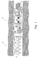
- a rock having a relatively thin ore-bearing formation 11 extending therethrough.
- the extension and approximate thickness of the ore-bearing formation has been determined by drilling from the surface of the ground above the formation.
- a drift 12 has been made through the rock so as to have the ore-bearing formation 11 extending therealong.
- the extension (in one direction) and approximate thickness t of the ore-bearing formation determined is indicated in Figs. 1 and 3 by two spaced dashed lines extending along the drift.
- a drill 13 having a diameter d substantially corresponding to the approximate thickness t of the ore-bearing layer 11 determined is used to drill a first hole H 1 along an axis A 1 extending along an approximate mid-plane M of the layer 11 ( Fig. 1 ) .
- a second hole H 2 is drilled along a second axis A 2 also extending along the approximate mid-plane of the ore-bearing layer 11.
- the axes A 1 and A 2 are parallel if the layer is a 'plane' layer, but they may as well be non-parallel if the layer is curved.
- the spacing S between the axes A 1 and A 2 is chosen such that the holes H 1 and H 2 intersect or overlap one another as shown in Fig. 1 . In other words, the spacing s is less than the drill diameter d.
- more or less material is left unbroken in areas where two holes do not intersect.
- the drill cuttings yielded are continuously collected.
- a section of a boring rig similar to the one shown in figs. 1-3 is shown in detail.
- a boring unit 20 which is supported on a substructure of a boring rig, whereof there are shown two longitudinal side members of said rig substructure which are indicated at 21 and 22.
- the boring unit 20 is comprised of a front frame portion 23 and a rear frame portion 24 which are separated by separation and strengthening elements formed as linear guide means 25 for a bore string rotation and forcing means which is indicated as an integral unit with numeral 26.
- front and rear concerns front part and rear part respectively of the boring unit 20 and does not concern the front or rear part of the boring rig carrying the boring unit.
- a bore string rotation and forcing means 26 is active so as to rotate and press forward a bore string 27, carrying at its distal end a cutter head 29, which is used for obtaining the rock disintegrating/excavating operation.
- the bore string 27 consists of a number of axially aligned, connected bore string components 28, which are added to the bore string in a manner which is not part of the invention and therefore not further discussed here.
- the boring unit 20 is pivotally connected to the substructure over pivot means 30 in the form of rotation joints between the rear frame portion 24 and a force transmitting means 34 positioned on a side member 22 of the rig substructure.
- the rotation joint 30 is positioned at the bottom part of the boring unit and in more in particular at the bottom part of the rear frame portion 24.
- each actuator 41 includes a rotator, which may be a hydraulic, pneumatic or electric rotator, which is pivotally attached to a side member 21 and is arranged to rotate a threaded bar, which in turn is engaged with a nut which is pivotally attached to the front frame portion 23. Rotation of the actuators 41 results in altered elevation of the boring unit with respect to the horizontal. It should be noted that the actuators 41 can be comprised of other kinds of linear motors such as for example hydraulic cylinders.
- Attached to the rig substructure are a number of stabilizing means which are formed by on the one hand horizontal stabilizing means and on the other hand by vertical stabilizing means.
- the horizontal stabilizing means 31 and 32 are comprised of horizontally acting horizontal jacks having engagement ends for engagement with the rock face of the drift, inside which the rig is intended to be positioned in operation.
- Each horizontal jack 31 is attached to the rig substructure over a holder 33 which in the shown embodiment is integral with the force transmitting means 34, whereby advantageous force transmission is obtained between the cutter head, the boring unit, the substructure and the horizontal stabilizing means.
- each corresponding holder for a horizontal jack 32 is attached to a side member 21 of the rig substructure and may for stability reasons be directly or indirectly connected to a holder for the actuator 41 for pivoting the boring unit 20.
- the vertical stabilizing means include in the shown embodiment four vertical support jacks 35, 36, 37 (the fourth is not shown) which are active against the drift floor, and which may be set so as to lift the boring rig and in particular its propulsive wheels from the drift floor in order to allow accurate positioning in respect of said floor as is mentioned above.
- each vertical roof jack 38, 39 is preferably connected to or may even be integral with the holder for a vertical support jack. In any case there is preferably provided for force transmission over a force transmitting means 40 between a vertical roof jack 38 and adjacent vertical support jack.
- a pair of sideways stabilizing means in the form of hydraulic jacks 42 which are positioned at the top of the boring unit. They are in particular constructed as having their cylinder tubes forming stabilizing tubes separating the front frame portion and the rear frame portion of the boring unit 20.
- the sideways stabilizing means are intended to be engaged against a drift wall so as to resist axial forces in the bore string 27 which would otherwise tend to tilt the boring rig during operation.
- a computerized control unit controls the different stabilizing means and the actuators for pivoting the boring unit so as to position both the boring rig and the boring unit prior to operation so as to obtain a side elevation angle for boring purposes.
- the means for positioning and controlling the boring unit therefore can be said to include the means for positioning and stabilizing the boring rig as well as the means acting between a boring rig substructure and the boring unit 20. Also the boring rig propulsion and steering means contribute in positioning and directing the bore string.
- the filled simple arrows in fig. 4 indicate setting directions for the different stabilizing means upon positioning and stabilization.
- the double arrows indicate movement up and down of the front frame portion upon actuation on the actuators 41 for pivoting the boring unit.
- Fig. 5 basically shows the same elements as fig. 4 , but here is also briefly illustrated (by the filled simple arrows) the forces acting on this part of the boring rig. To this end there is indicated that on the cutter head there is acting a torque as well as an axial force because of the rotational and pressing power supplied to the bore string.
- the substructure could be made up from different elements, such as from plate-shaped elements.
- the boring unit may be constructed having for example box-like structure instead of the relatively open structure shown in order to separated frames.
- the jacks may be operated differently, for example as screw jacks instead of hydraulic jacks.
- the boring unit may be attached differently to the substructure, for example over a centrally positioned rotation joint instead of a sideways positioned rotation joint as is shown.
- the boring unit can have the rotation joints attached at its front region so as to allow it to be pivoted around the front portion. This gives greater possibilities of having the elevation angle negative and to excavate in directions obliquely downwards.
Landscapes
- Engineering & Computer Science (AREA)
- Mining & Mineral Resources (AREA)
- Mechanical Engineering (AREA)
- Life Sciences & Earth Sciences (AREA)
- General Life Sciences & Earth Sciences (AREA)
- Geochemistry & Mineralogy (AREA)
- Geology (AREA)
- Earth Drilling (AREA)
- Road Repair (AREA)
- Steroid Compounds (AREA)
Claims (20)
- Bohrgestell (14) für unterirdisches Abbaubohren, umfassend einen Unterbau (21, 22), Vortriebsmittel für eine Gestellbewegung entlang eines Tunnels und eine Vielzahl von Stabilisierungsmitteln (31, 32, 35, 36, 37, 38, 39, 42), die an dem Unterbau angebracht sind, wobei die Stabilisierungsmittel jeweils dazu vorgesehen sind, in aktiven Stellungen gegen eine benachbarte Felsfläche gepresst zu werden und die Vielzahl von Stabilisierungsmitteln vertikal wirkende Stabilisierungsmittel (35, 36, 37, 38, 39) einschließt, und das Bohrgestell weiterhin eine Bohreinheit (20) umfasst, die Rotations- und Anpressmittel (26) aufweist, die auf einen Schneidkopf (29) wirken, wobei das Gestell eine erste Richtung allgemeiner Bewegung entlang des Tunnels und zwei Richtungen seitwärts von der ersten Richtung besitzt und die Bohreinheit (20) auf dem Unterbau für eine Schwenkbewegung der Bohreinheit in eine Betriebsstellung schwenkbar angeordnet ist, dadurch gekennzeichnet, dass die Vielzahl von Stabilisierungsmitteln auch horizontal wirkende Stabilisierungsmittel (31, 32) aufweist und die Vielzahl von Stabilisierungsmitteln weiterhin wenigstens zwei Stabilisierungsmittel aufweist, die dazu vorgesehen sind, zwischen dem Unterbau und zwei Felsflächen zu wirken, die sich einander gegenüber liegen, wobei alle Stabilisierungsmittel in aktiver Stellung dazu geeignet sind, derart gegen eine benachbarte Felsfläche gepresst zu werden, dass sie Kräfte von der Bohreinheit (20), die während des Bohrens auftreten, auf die Felsfläche übertragen.
- Bohrgestell nach Anspruch 1, dadurch gekennzeichnet, dass die horizontalen Stabilisierungsmittel (31, 32) Mittel aufweisen, die dazu vorgesehen sind, zwischen dem Unterbau und zwei Felsflächen zu wirken, die sich einander gegenüber liegen.
- Bohrgestell nach Anspruch 1 oder 2, dadurch gekennzeichnet, dass die vertikalen Stabilisierungsmittel (35, 36, 37, 38, 39) erste Mittel, die dazu vorgesehen sind, zwischen dem Unterbau und dem Tunnelboden zu wirken, und zweite Mittel aufweisen, die dazu vorgesehen sind, zwischen dem Unterbau und der Tunneldecke zu wirken.
- Bohrgestell nach einem der vorhergehenden Ansprüche, dadurch gekennzeichnet, dass die Bohreinheit (20) zum Betrieb der Bohreinheit in der Schwenkebene und im wesentlichen senkrecht zu der ersten Richtung allgemeiner Bewegung des Gestells schwenkbar ist.
- Bohrgestell nach einem der vorhergehenden Ansprüche, dadurch gekennzeichnet, dass die Bohreinheit (20) über Schwenkmittel (30) schwenkbar ist, die aus Drehgelenken bestehen, die an dem Unterbau (22) an verschiedenen Stätten entlang der ersten Richtung angebracht sind.
- Bohrgestell nach einem der vorhergehenden Ansprüche, dadurch gekennzeichnet, dass wenigstens ein Aktuator (41) zwischen dem Unterbau (21) und der Bohreinheit (20) angeordnet ist, um die Bohreinheit in Schwenkrichtung zu bewegen.
- Bohrgestell nach einem der vorhergehenden Ansprüche, dadurch gekennzeichnet, dass die horizontalen Stabilisierungsmittel seitwärts gerichtete horizontale Stempel (31, 32) sind, die auf jeder Seite des Unterbaus angeordnet sind.
- Bohrgestell nach Anspruch 7, dadurch gekennzeichnet, dass zwischen jedem Drehgelenk (30) und einem benachbarten Halter (33) für einen Horizontalstempel kraftübertragende Mittel (34) vorgesehen sind.
- Bohrgestell nach Anspruch 7 oder 8, dadurch gekennzeichnet, dass jeder Halter (30) für einen Horizontalstempel an einem jeweiligen Seitenelement des Unterbaus angebracht ist.
- Bohrgestell nach Anspruch 7, 8 oder 9, dadurch gekennzeichnet, dass jeder Halter (30) für einen Horizontalstempel integral mit einem stationären Teil jeweiliger Gelenkmittel ausgebildet ist.
- Bohrgestell nach einem der vorhergehenden Ansprüche, dadurch gekennzeichnet, dass die vertikalen Stabilisierungsmittel (35, 36, 37, 38, 39) vertikal ausgerichtete Vertikalstempel sind, die an dem Unterbau angeordnet sind.
- Bohrgestell nach einem der vorhergehenden Ansprüche, dadurch gekennzeichnet, dass die Bohreinheit (20) schwenkbar an einem Bodenbereich des Unterbaus angebracht ist.
- Bohrgestell nach einem der vorhergehenden Ansprüche, dadurch gekennzeichnet, dass die Bohreinheit (30) schwenkbar an einem rückwärtigen Teil des Unterbaus angebracht ist.
- Bohrgestell nach einem der vorhergehenden Ansprüche, dadurch gekennzeichnet, dass die Bohreinheit einen vorderen (23) und einen hinteren (24) Rahmenbereich aufweist, die durch lineare Führungsmittel (25) zum Führen der den Bohrstrang drehenden und anpressenden Mittel (26) getrennt sind.
- Bohrgestell nach Anspruch 14, dadurch gekennzeichnet, dass die Schwenkmittel (30) an dem rückwärtigen Rahmenbereich (24) angebracht sind.
- Bohrgestell nach Anspruch 14 oder 15, dadurch gekennzeichnet, dass jeder Rahmenbereich aus einem Stück Metallplatte besteht.
- Bohrgestell nach einem der vorhergehenden Ansprüche, dadurch gekennzeichnet, dass die Bohreinheit (20) an einem oberen, rückwärtigen Bereich mit seitwärts gerichteten Stabilisierungsmitteln (42) versehen ist, um gegen eine Felsfläche in Richtungen zu wirken, die im wesentlichen der Betriebsrichtung der Bohreinheit (20) gegenüberliegen.
- Bohrgestell nach einem der vorhergehenden Ansprüche, dadurch gekennzeichnet, dass es eine Steuereinheit zum Steuern der Einstellung der Stabilisierungsmittel (31, 32, 35, 36, 37, 38, 39, 42) und zum Steuern der Positionierung und Neigung der Bohreinheit (20) aufweist.
- Bohrgestell nach Anspruch 18, dadurch gekennzeichnet, dass die Steuereinheit in der Lage ist, die Stabilisierungsmittel (31, 32, 35, 36, 37, 38, 39, 42) derart einzustellen, dass sie das Bohrgestell (14) in vorbestimmen Winkeln mit Bezug auf einen Traggrund neigen.
- Bohrgestell nach einem der vorhergehenden Ansprüche, dadurch gekennzeichnet, dass es eine Versorgung für Komponenten für den Bohrstrang und Mittel zum Verbinden des Rohrstrangs umfasst.
Priority Applications (1)
| Application Number | Priority Date | Filing Date | Title |
|---|---|---|---|
| PL04800344T PL1685309T3 (pl) | 2003-11-21 | 2004-11-17 | Urządzenie wiertnicze |
Applications Claiming Priority (5)
| Application Number | Priority Date | Filing Date | Title |
|---|---|---|---|
| SE0303100A SE0303100D0 (sv) | 2003-11-21 | 2003-11-21 | A rock drilling method |
| SE0400057A SE528664C2 (sv) | 2004-01-14 | 2004-01-14 | Hållarnyckel för bergborrningsmaskin och bergborrningsmaskin inkluderande en sådan hållarnyckel |
| SE0400401A SE0400401D0 (sv) | 2004-02-20 | 2004-02-20 | Drill string component |
| SE0400986A SE526134C2 (sv) | 2003-11-21 | 2004-04-16 | Borrigg för produktionsborrning i begränsande utrymmen |
| PCT/SE2004/001682 WO2005049965A1 (en) | 2003-11-21 | 2004-11-17 | Boring rig |
Publications (2)
| Publication Number | Publication Date |
|---|---|
| EP1685309A1 EP1685309A1 (de) | 2006-08-02 |
| EP1685309B1 true EP1685309B1 (de) | 2009-12-23 |
Family
ID=32303643
Family Applications (1)
| Application Number | Title | Priority Date | Filing Date |
|---|---|---|---|
| EP04800344A Expired - Lifetime EP1685309B1 (de) | 2003-11-21 | 2004-11-17 | Bohrgestell |
Country Status (9)
| Country | Link |
|---|---|
| US (1) | US7357458B2 (de) |
| EP (1) | EP1685309B1 (de) |
| AT (1) | ATE453039T1 (de) |
| AU (1) | AU2004291822B2 (de) |
| CA (1) | CA2541718C (de) |
| DE (1) | DE602004024818D1 (de) |
| PL (1) | PL1685309T3 (de) |
| SE (1) | SE526134C2 (de) |
| WO (1) | WO2005049965A1 (de) |
Families Citing this family (6)
| Publication number | Priority date | Publication date | Assignee | Title |
|---|---|---|---|---|
| AT502469B1 (de) * | 2005-08-03 | 2008-03-15 | Voest Alpine Bergtechnik | Startwagen für eine bohrvorrichtung |
| GB0712895D0 (en) * | 2007-07-03 | 2007-08-15 | Thomas Gareth J | Excavator vehicle |
| CN107255031B (zh) * | 2011-08-03 | 2019-10-25 | 久益环球地下采矿有限责任公司 | 采掘机的稳定系统 |
| SE536713C2 (sv) * | 2012-10-30 | 2014-06-10 | Atlas Copco Rock Drills Ab | Borrigg jämte förfarande för manövrering av en borrigg |
| SE538353C2 (sv) * | 2014-03-12 | 2016-05-24 | Atlas Copco Rock Drills Ab | Borrigg och förfarande |
| CN104975855A (zh) * | 2015-06-19 | 2015-10-14 | 黄斌 | 一种矿石开采用钻孔机 |
Family Cites Families (13)
| Publication number | Priority date | Publication date | Assignee | Title |
|---|---|---|---|---|
| US2176885A (en) * | 1937-07-14 | 1939-10-24 | Mineral Cutting Machine Compan | Mining apparatus |
| US2726064A (en) * | 1949-05-24 | 1955-12-06 | Joy Mfg Co | Drilling and conveying apparatus |
| GB800864A (en) | 1955-08-02 | 1958-09-03 | Coal Industry Patents Ltd | Improvements in or relating to mining machines |
| US2979320A (en) * | 1958-03-12 | 1961-04-11 | Salem Tool Co | Tiltable deep mining auger machine |
| US3167354A (en) * | 1962-08-24 | 1965-01-26 | Ingersoll Rand Co | Drilling method for mining thin ore bodies |
| GB1311094A (en) * | 1969-03-25 | 1973-03-21 | Dubois M | Machine and process for digging undergrojnd galleries |
| US3647263A (en) * | 1970-03-19 | 1972-03-07 | Atlas Copco Ab | Tunnelling machines and the like |
| US3963080A (en) * | 1975-01-29 | 1976-06-15 | Dresser Industries, Inc. | Tunneling machine for boring a side drift |
| CA1033373A (en) * | 1975-04-17 | 1978-06-20 | Karl-Gunther Bechem | Mining machine and a method for mining of minerals |
| DE2843055A1 (de) * | 1977-10-07 | 1979-04-19 | Beukenberg Maschf | Einrichtung zum hereingewinnen von mineralien im insbesondere untertaegigen bergbau |
| FR2461806A1 (fr) * | 1979-07-20 | 1981-02-06 | Stephanois Constr Meca | Machine de creusement comportant un bras muni d'un outil d'abattage et orientable |
| SE466065B (sv) * | 1990-12-13 | 1991-12-09 | Atlas Copco Constr & Mining | Tunnelborrningsmaskin |
| US6857706B2 (en) * | 2001-12-10 | 2005-02-22 | Placer Dome Technical Services Limited | Mining method for steeply dipping ore bodies |
-
2004
- 2004-04-16 SE SE0400986A patent/SE526134C2/sv unknown
- 2004-11-17 PL PL04800344T patent/PL1685309T3/pl unknown
- 2004-11-17 AT AT04800344T patent/ATE453039T1/de not_active IP Right Cessation
- 2004-11-17 AU AU2004291822A patent/AU2004291822B2/en not_active Ceased
- 2004-11-17 WO PCT/SE2004/001682 patent/WO2005049965A1/en not_active Ceased
- 2004-11-17 CA CA2541718A patent/CA2541718C/en not_active Expired - Fee Related
- 2004-11-17 US US10/573,100 patent/US7357458B2/en not_active Expired - Fee Related
- 2004-11-17 EP EP04800344A patent/EP1685309B1/de not_active Expired - Lifetime
- 2004-11-17 DE DE602004024818T patent/DE602004024818D1/de not_active Expired - Lifetime
Also Published As
| Publication number | Publication date |
|---|---|
| AU2004291822B2 (en) | 2009-10-29 |
| SE526134C2 (sv) | 2005-07-12 |
| WO2005049965A1 (en) | 2005-06-02 |
| ATE453039T1 (de) | 2010-01-15 |
| CA2541718C (en) | 2012-08-07 |
| PL1685309T3 (pl) | 2010-06-30 |
| SE0400986D0 (sv) | 2004-04-16 |
| AU2004291822A1 (en) | 2005-06-02 |
| US20070035172A1 (en) | 2007-02-15 |
| SE0400986L (sv) | 2005-05-22 |
| CA2541718A1 (en) | 2005-06-02 |
| US7357458B2 (en) | 2008-04-15 |
| DE602004024818D1 (de) | 2010-02-04 |
| EP1685309A1 (de) | 2006-08-02 |
Similar Documents
| Publication | Publication Date | Title |
|---|---|---|
| US8317430B2 (en) | Crawler-type and height adjustment drilling machine for setting roof and side wall anchor bolts and anchor cables | |
| CA2561803C (en) | Mining apparatus with precision navigation system | |
| US4160566A (en) | Mining apparatus | |
| CN110374590A (zh) | 石膏石用多功能开采设备 | |
| US7357458B2 (en) | Boring rig | |
| JPS5985091A (ja) | 鉱山用掘削機械 | |
| ZA200602589B (en) | Boring Rig | |
| CN111684143B (zh) | 带有尖角切削器的掘进联合机 | |
| EP3735514B1 (de) | Vorrichtung an tunnelbohrmaschinen für bohrarbeiten ohne bedienungspersonal im bohrloch | |
| US7192093B2 (en) | Excavation apparatus and method | |
| CA3083110C (en) | Autonomous drilling machine for the construction of service shafts and open shafts | |
| EP2914797B1 (de) | Bohrgestell und verfahren zur bedienung eines bohrgestells | |
| EP3119989B1 (de) | Bohrgestell und verfahren | |
| JPH0119040B2 (de) | ||
| JP2000213266A (ja) | 削孔ドリルジャンボ | |
| RU2169840C1 (ru) | Буровая машина для проведения восстающих скважин | |
| US5641207A (en) | Mining machine | |
| RU2126888C1 (ru) | Проходческий комбайн | |
| MXPA06005582A (es) | Torre de perforacion | |
| SU1666696A1 (ru) | Проходческий комбайн | |
| ZA200608801B (en) | Mining apparatus with precision navigation system | |
| JPH02209521A (ja) | 地中壁掘削機用の偏位修正装置 | |
| JPS62133297A (ja) | トンネル掘進機 |
Legal Events
| Date | Code | Title | Description |
|---|---|---|---|
| PUAI | Public reference made under article 153(3) epc to a published international application that has entered the european phase |
Free format text: ORIGINAL CODE: 0009012 |
|
| 17P | Request for examination filed |
Effective date: 20060317 |
|
| AK | Designated contracting states |
Kind code of ref document: A1 Designated state(s): AT BE BG CH CY CZ DE DK EE ES FI FR GB GR HU IE IS IT LI LU MC NL PL PT RO SE SI SK TR |
|
| DAX | Request for extension of the european patent (deleted) | ||
| 17Q | First examination report despatched |
Effective date: 20070326 |
|
| GRAP | Despatch of communication of intention to grant a patent |
Free format text: ORIGINAL CODE: EPIDOSNIGR1 |
|
| GRAS | Grant fee paid |
Free format text: ORIGINAL CODE: EPIDOSNIGR3 |
|
| GRAA | (expected) grant |
Free format text: ORIGINAL CODE: 0009210 |
|
| AK | Designated contracting states |
Kind code of ref document: B1 Designated state(s): AT BE BG CH CY CZ DE DK EE ES FI FR GB GR HU IE IS IT LI LU MC NL PL PT RO SE SI SK TR |
|
| REG | Reference to a national code |
Ref country code: GB Ref legal event code: FG4D |
|
| REG | Reference to a national code |
Ref country code: CH Ref legal event code: EP |
|
| REG | Reference to a national code |
Ref country code: IE Ref legal event code: FG4D |
|
| REF | Corresponds to: |
Ref document number: 602004024818 Country of ref document: DE Date of ref document: 20100204 Kind code of ref document: P |
|
| REG | Reference to a national code |
Ref country code: NL Ref legal event code: VDEP Effective date: 20091223 |
|
| PG25 | Lapsed in a contracting state [announced via postgrant information from national office to epo] |
Ref country code: SE Free format text: LAPSE BECAUSE OF FAILURE TO SUBMIT A TRANSLATION OF THE DESCRIPTION OR TO PAY THE FEE WITHIN THE PRESCRIBED TIME-LIMIT Effective date: 20091223 |
|
| PG25 | Lapsed in a contracting state [announced via postgrant information from national office to epo] |
Ref country code: SI Free format text: LAPSE BECAUSE OF FAILURE TO SUBMIT A TRANSLATION OF THE DESCRIPTION OR TO PAY THE FEE WITHIN THE PRESCRIBED TIME-LIMIT Effective date: 20091223 |
|
| PG25 | Lapsed in a contracting state [announced via postgrant information from national office to epo] |
Ref country code: AT Free format text: LAPSE BECAUSE OF FAILURE TO SUBMIT A TRANSLATION OF THE DESCRIPTION OR TO PAY THE FEE WITHIN THE PRESCRIBED TIME-LIMIT Effective date: 20091223 |
|
| PG25 | Lapsed in a contracting state [announced via postgrant information from national office to epo] |
Ref country code: NL Free format text: LAPSE BECAUSE OF FAILURE TO SUBMIT A TRANSLATION OF THE DESCRIPTION OR TO PAY THE FEE WITHIN THE PRESCRIBED TIME-LIMIT Effective date: 20091223 Ref country code: BG Free format text: LAPSE BECAUSE OF FAILURE TO SUBMIT A TRANSLATION OF THE DESCRIPTION OR TO PAY THE FEE WITHIN THE PRESCRIBED TIME-LIMIT Effective date: 20100323 Ref country code: EE Free format text: LAPSE BECAUSE OF FAILURE TO SUBMIT A TRANSLATION OF THE DESCRIPTION OR TO PAY THE FEE WITHIN THE PRESCRIBED TIME-LIMIT Effective date: 20091223 Ref country code: IS Free format text: LAPSE BECAUSE OF FAILURE TO SUBMIT A TRANSLATION OF THE DESCRIPTION OR TO PAY THE FEE WITHIN THE PRESCRIBED TIME-LIMIT Effective date: 20100423 Ref country code: ES Free format text: LAPSE BECAUSE OF FAILURE TO SUBMIT A TRANSLATION OF THE DESCRIPTION OR TO PAY THE FEE WITHIN THE PRESCRIBED TIME-LIMIT Effective date: 20100403 Ref country code: PT Free format text: LAPSE BECAUSE OF FAILURE TO SUBMIT A TRANSLATION OF THE DESCRIPTION OR TO PAY THE FEE WITHIN THE PRESCRIBED TIME-LIMIT Effective date: 20100423 Ref country code: RO Free format text: LAPSE BECAUSE OF FAILURE TO SUBMIT A TRANSLATION OF THE DESCRIPTION OR TO PAY THE FEE WITHIN THE PRESCRIBED TIME-LIMIT Effective date: 20091223 |
|
| PG25 | Lapsed in a contracting state [announced via postgrant information from national office to epo] |
Ref country code: CZ Free format text: LAPSE BECAUSE OF FAILURE TO SUBMIT A TRANSLATION OF THE DESCRIPTION OR TO PAY THE FEE WITHIN THE PRESCRIBED TIME-LIMIT Effective date: 20091223 Ref country code: SK Free format text: LAPSE BECAUSE OF FAILURE TO SUBMIT A TRANSLATION OF THE DESCRIPTION OR TO PAY THE FEE WITHIN THE PRESCRIBED TIME-LIMIT Effective date: 20091223 Ref country code: BE Free format text: LAPSE BECAUSE OF FAILURE TO SUBMIT A TRANSLATION OF THE DESCRIPTION OR TO PAY THE FEE WITHIN THE PRESCRIBED TIME-LIMIT Effective date: 20091223 |
|
| PG25 | Lapsed in a contracting state [announced via postgrant information from national office to epo] |
Ref country code: GR Free format text: LAPSE BECAUSE OF FAILURE TO SUBMIT A TRANSLATION OF THE DESCRIPTION OR TO PAY THE FEE WITHIN THE PRESCRIBED TIME-LIMIT Effective date: 20100324 Ref country code: CY Free format text: LAPSE BECAUSE OF FAILURE TO SUBMIT A TRANSLATION OF THE DESCRIPTION OR TO PAY THE FEE WITHIN THE PRESCRIBED TIME-LIMIT Effective date: 20091223 |
|
| PLBE | No opposition filed within time limit |
Free format text: ORIGINAL CODE: 0009261 |
|
| STAA | Information on the status of an ep patent application or granted ep patent |
Free format text: STATUS: NO OPPOSITION FILED WITHIN TIME LIMIT |
|
| 26N | No opposition filed |
Effective date: 20100924 |
|
| PG25 | Lapsed in a contracting state [announced via postgrant information from national office to epo] |
Ref country code: DK Free format text: LAPSE BECAUSE OF FAILURE TO SUBMIT A TRANSLATION OF THE DESCRIPTION OR TO PAY THE FEE WITHIN THE PRESCRIBED TIME-LIMIT Effective date: 20091223 |
|
| PG25 | Lapsed in a contracting state [announced via postgrant information from national office to epo] |
Ref country code: IT Free format text: LAPSE BECAUSE OF FAILURE TO SUBMIT A TRANSLATION OF THE DESCRIPTION OR TO PAY THE FEE WITHIN THE PRESCRIBED TIME-LIMIT Effective date: 20091223 |
|
| PG25 | Lapsed in a contracting state [announced via postgrant information from national office to epo] |
Ref country code: MC Free format text: LAPSE BECAUSE OF NON-PAYMENT OF DUE FEES Effective date: 20101130 |
|
| GBPC | Gb: european patent ceased through non-payment of renewal fee |
Effective date: 20101117 |
|
| REG | Reference to a national code |
Ref country code: FR Ref legal event code: ST Effective date: 20110801 |
|
| PG25 | Lapsed in a contracting state [announced via postgrant information from national office to epo] |
Ref country code: FR Free format text: LAPSE BECAUSE OF NON-PAYMENT OF DUE FEES Effective date: 20101130 Ref country code: IE Free format text: LAPSE BECAUSE OF NON-PAYMENT OF DUE FEES Effective date: 20101117 |
|
| PG25 | Lapsed in a contracting state [announced via postgrant information from national office to epo] |
Ref country code: GB Free format text: LAPSE BECAUSE OF NON-PAYMENT OF DUE FEES Effective date: 20101117 |
|
| PG25 | Lapsed in a contracting state [announced via postgrant information from national office to epo] |
Ref country code: LU Free format text: LAPSE BECAUSE OF NON-PAYMENT OF DUE FEES Effective date: 20101117 Ref country code: HU Free format text: LAPSE BECAUSE OF FAILURE TO SUBMIT A TRANSLATION OF THE DESCRIPTION OR TO PAY THE FEE WITHIN THE PRESCRIBED TIME-LIMIT Effective date: 20100624 |
|
| PG25 | Lapsed in a contracting state [announced via postgrant information from national office to epo] |
Ref country code: TR Free format text: LAPSE BECAUSE OF FAILURE TO SUBMIT A TRANSLATION OF THE DESCRIPTION OR TO PAY THE FEE WITHIN THE PRESCRIBED TIME-LIMIT Effective date: 20091223 |
|
| PGFP | Annual fee paid to national office [announced via postgrant information from national office to epo] |
Ref country code: CH Payment date: 20151127 Year of fee payment: 12 |
|
| REG | Reference to a national code |
Ref country code: CH Ref legal event code: PL |
|
| PG25 | Lapsed in a contracting state [announced via postgrant information from national office to epo] |
Ref country code: LI Free format text: LAPSE BECAUSE OF NON-PAYMENT OF DUE FEES Effective date: 20161130 Ref country code: CH Free format text: LAPSE BECAUSE OF NON-PAYMENT OF DUE FEES Effective date: 20161130 |
|
| PGFP | Annual fee paid to national office [announced via postgrant information from national office to epo] |
Ref country code: DE Payment date: 20171129 Year of fee payment: 14 |
|
| REG | Reference to a national code |
Ref country code: DE Ref legal event code: R119 Ref document number: 602004024818 Country of ref document: DE |
|
| PG25 | Lapsed in a contracting state [announced via postgrant information from national office to epo] |
Ref country code: DE Free format text: LAPSE BECAUSE OF NON-PAYMENT OF DUE FEES Effective date: 20190601 |
|
| PGFP | Annual fee paid to national office [announced via postgrant information from national office to epo] |
Ref country code: FI Payment date: 20191127 Year of fee payment: 16 |
|
| PGFP | Annual fee paid to national office [announced via postgrant information from national office to epo] |
Ref country code: PL Payment date: 20191031 Year of fee payment: 16 |
|
| REG | Reference to a national code |
Ref country code: FI Ref legal event code: MAE |
|
| PG25 | Lapsed in a contracting state [announced via postgrant information from national office to epo] |
Ref country code: FI Free format text: LAPSE BECAUSE OF NON-PAYMENT OF DUE FEES Effective date: 20201117 |
|
| PG25 | Lapsed in a contracting state [announced via postgrant information from national office to epo] |
Ref country code: PL Free format text: LAPSE BECAUSE OF NON-PAYMENT OF DUE FEES Effective date: 20201117 |