US4057068A - Enclosure for and method of enclosing a body implantable pulse generator - Google Patents
Enclosure for and method of enclosing a body implantable pulse generator Download PDFInfo
- Publication number
- US4057068A US4057068A US05/659,650 US65965076A US4057068A US 4057068 A US4057068 A US 4057068A US 65965076 A US65965076 A US 65965076A US 4057068 A US4057068 A US 4057068A
- Authority
- US
- United States
- Prior art keywords
- circular
- enclosure
- platform
- termini
- web
- Prior art date
- Legal status (The legal status is an assumption and is not a legal conclusion. Google has not performed a legal analysis and makes no representation as to the accuracy of the status listed.)
- Expired - Lifetime
Links
Images
Classifications
-
- A—HUMAN NECESSITIES
- A61—MEDICAL OR VETERINARY SCIENCE; HYGIENE
- A61N—ELECTROTHERAPY; MAGNETOTHERAPY; RADIATION THERAPY; ULTRASOUND THERAPY
- A61N1/00—Electrotherapy; Circuits therefor
- A61N1/18—Applying electric currents by contact electrodes
- A61N1/32—Applying electric currents by contact electrodes alternating or intermittent currents
- A61N1/36—Applying electric currents by contact electrodes alternating or intermittent currents for stimulation
- A61N1/372—Arrangements in connection with the implantation of stimulators
- A61N1/375—Constructional arrangements, e.g. casings
-
- H—ELECTRICITY
- H05—ELECTRIC TECHNIQUES NOT OTHERWISE PROVIDED FOR
- H05K—PRINTED CIRCUITS; CASINGS OR CONSTRUCTIONAL DETAILS OF ELECTRIC APPARATUS; MANUFACTURE OF ASSEMBLAGES OF ELECTRICAL COMPONENTS
- H05K5/00—Casings, cabinets or drawers for electric apparatus
- H05K5/06—Hermetically-sealed casings
Definitions
- Body implantable pulse generators are known to the prior art, their present principal form being the well-known cardiac pacemaker.
- cardiac pacemaker In the body implanted environment, it is generally recognized that an enclosed and hermetically sealed pulse generator is more reliable as a result of the known and controlled environment provided by the hermetic seal which alleviates various design and performance uncertainties.
- Typical prior art pulse generator hermetically sealed enclosures are formed of a plurality of weldable members with the hermetic seal being accomplished by welding the members to each other around the assembled pulse generator.
- All enclosure configurations known to the inventor present a complex weld geometry, usually at least one weld joint which is generally rectangular having rounded corners, which results in high fabrication costs.
- the present invention provides an enclosure for a body implantable pulse generator which may be hermetically sealed with a single continuous circular weld.
- the enclosure is formed of two members each having a continuous side wall with each side wall having a generally circular terminus of substantially equal diameter. With the side wall termini in abutment, the enclosure may be rotated about the axes of the circular termini to present the entirety of the abutment to a single weldment location. In this manner, the enclosure of the present invention may be welded, and hermetically sealed in known manner, without the complex weld geometry of the prior art enclosures.
- the present invention provides at least one platform through which feedthrough terminals may extend to provide electrical communication with the enclosed pulse generator.
- the platform is configured such that the terminals do not extend beyond the general overall dimensions of the enclosure while being easily accessable within the interior of the enclosure.
- the platform is formed entirely along a chord of the circular terminus of one side wall with a web extending between the platform and side wall terminus to complete the enclosure.
- the platform has a first portion lying along the chord of the circular terminus of one side wall and a second portion extending between the first portion and the side wall terminus, a web again extending between both platform portions and the side wall terminus to complete the enclosure.
- the second platform portion may be formed at an oblique angle to both the first portion and web to facilitate securement of a feedthrough terminal therein and access thereto within and without the enclosure.
- one or both of the members forming the enclosure may be provided with one or more platforms within the sense of the present invention.
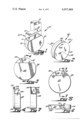
- FIG. 1 illustrates one of the several prior art pulse generator enclosures.
- FIG. 2 illustrates the overall configuration of the enclosure of the present invention and the manner in which a hermetic seal is accomplished with a single continuous circular weld.
- FIG. 3 illustrates a side view of a preferred embodiment of the invention illustrated generally in FIG. 2.
- FIG. 4 illustrates a cross-section taken through the line 4--4 in FIG. 3.
- FIG. 5 illustrates a side view of another preferred embodiment of the invention illustrated generally in FIG. 2.
- FIG. 6 shows a top view of the embodiment of FIG. 5.
- FIG. 7 shows a cross-section taken along the line 7--7 in FIG. 5.
- FIG. 1 illustrates one of the several known pulse generator enclosures having the generally rectangular weld joint discussed above.
- the main body 10 of the enclosure of FIG. 1 is formed of first and second members 11 and 12 respectively.
- the members 11 and 12 are truncated cup-shaped members having the ends of their side wall in abutment with each other to form a first weld joint 13.
- a generally rectangular plate 14 is placed over the open end 15 of the member 10 and welded in position, the weld joint being generally rectangular having rounded corners.
- Two feedthrough terminals 16 pass through the plate 14 to provide an electrical communication with the enclosed pulse generator.
- That portion of the terminal 16 on the outside of the enclosure may be connected to a lead harness or other known device by which an external lead may be placed into electrical communication with the enclosed pulse generator through the feedthrough terminal 16.
- a shroud 17 may be employed to protect the external lead connection and for other known purposes.
- Enclosure 20 is formed of first and second members or segments 21 and 22 each having a main wall 23 (one shown) and continuous side walls 24.
- the side walls 24 are generally cylindrical and have generally circular termini of substantially the same diameter.
- the axes of the side walls 24 and their circular termini coincide and are illustrated by the line 25 through the main walls 23.
- the entirety of the abutment of the sidewalls 24 can be welded with only a simple rotational motion being required.
- the welding may be effected through electron beam or any other welding technique.
- Members 21 and 22 may be of any weldable material capable of withstanding the environment and providing the desired sealing, titanium, for example.
- FIG. 2 illustrates the general overall configuration of the enclosure 20 of the present invention.
- FIG. 3 illustrates a preferred embodiment of one or both of the members 21 and 22 which makes special provision for an electrical communication with the enclosed pulse generator without effect on the circular abutment of the side walls 24.
- at least the terminus of the side wall 24 is continuous and circular while the main wall 23 is truncated.
- a platform 28 subtends a portion of the arc of the sidewall 24 terminus and, in the illustrated embodiment, extends from one end of the arc to the other along a chord of the circle formed by the side wall 24 terminus.
- a web 29 extends between the platform 28 and the terminus of the sidewall 24 to complete the enclosure.
- the platform 28 is provided to allow a feedthrough terminal 16 to pass through the sidewall 24 while the terminal remains within the general overall configuration of the enclosure 20. That is, the feedthrough terminal 16 lies within a volume which would be included within the enclosure if the sidewall 24 were cylindrical in its entirety and the platform 28 and web 29 were omitted. In this manner, electrical communication with the enclosed pulse generator may be provided without significant projection of a terminal, or other connecting member, beyond the general enclosure configuration. Of course, in some circumstances it may be desirable to have the terminal project beyond the general enclosure configuration in which case the terminal 16 may be elongated without departure from the scope of the present invention.
- FIGS. 3 and 4 may be identical to those known to the prior art and discussed with reference to FIG. 1, as may be all of the feedthrough terminals of like reference number discussed herein. Also, FIGS. 3-7 show only a single feedthrough terminal for the purpose of illustrating the cooperation between the terminal 16, the sidewall 24 and the various platforms and webs to be described herein. Any number of feedthrough terminals 16 may be employed within the embodiments of the present invention consistent with available space and the number necessary for the application in question.
- FIGS. 5-7 there is illustrated another preferred embodiment of one or both of the members 21 and 22 with special provision being made for electrical communication with the enclosed pulse generator without effect of the generally circular weld joint provided by the sidewall 24 termini.
- the terminus of the side wall 24 is continuous and circular.
- the platform of the embodiment of FIGS. 5-7 is formed of a first portion 30 lying along a chord of the circle formed by the terminus of the side wall 24 and a second portion 31 angularly disposed relative to the first portion and extending from the first portion toward the terminus of the side wall 24 within the arc of the circle formed by the terminus of the side wall 24 subtended by the chord along which the portion 30 lies.
- a web 32 extends between the platform portions 30 and 31 and the terminus of the side wall 24 to complete the enclosure. As illustrated, the platform portion 30 and web 32 are generally perpendicular to each other and the platform portion 31 forms an oblique angle with both the platform portion 30 and web 32 for reasons to be described more fully below.
- a feedthrough terminal 16 extends through the platform portion 31 to provide an electrical communication with the enclosed pulse generator with the external portion of the feedthrough terminal 16 lying within the general overall configuration of the enclosure. In some instances it may be desirable to have the feedthrough terminal 16 in the embodiment of FIGS. 5-7 project beyond the overall configuration of the enclosure. In such instances, the feedthrough terminal 16 may be elongated to provide the desired projection without departure from the scope of the present invention.
- the platform portion 31 forms an oblique angle with both the platform portion 30 and the web portion 32.
- the platform portion 31 may form an oblique angle with the platform portion 30 but be perpendicular to the web 32. It has been found, however, that securement of the terminal 16 within the platform portion 31 is more readily accomplished when the platform portion 31 is obliquely disposed relative to the web 32, as illustrated.
- the oblique arrangement of the platform portion 31 angles that portion of the feedthrough terminals 16 within the enclosure away from the main wall 23 thereby facilitating electrical connection between the pulse generator to be enclosed and the feedthrough terminal 16. While only one feedthrough terminal 16 is illustrated in the embodiment of FIGS. 5-7, and that terminal passes through the platform portion 31, it is to be understood that any number of terminal 16 may be employed within either of the platform portions 30 and 31 consistent with the space available and the number of terminals necessary for the desired application.
- any of the members illustrated in FIGS. 3-4 and 5-7 may be employed interchangeably with themselves or each other they or may be combined with a member having a side wall which is cylindrical in its entirety (having no platform or web).
- at least the termini of the side walls 24 be circular and of approximately the same diameter such that the termini will abut with each other.
- any of the illustrated or described embodiments may be interchangeably combined while still presenting the entirety of the abutment to the same weldment location with a simple rotational movement.
- the welding action will be directed at the outer surface of the sidewalls 24.
- a retaining ring 33 may be used with any of the embodiments illustrated or described in a manner known to the prior art.
- a shroud such as that illustrated at 17 and FIG. 1 may be configured to overlie the recessed areas described herein for reasons well known to the prior art.
- the terminals 16 may be secured within either of the webs 29 or 32, if desired.
- the web 32 and platform portion 30 may be combined into a single arcurate web surface with the terminals 16 extending through the platform portion 31. It is therefore to be understood that, within the scope of the appended claims, the invention may be practiced otherwise than as specifically described.
Landscapes
- Health & Medical Sciences (AREA)
- Engineering & Computer Science (AREA)
- Biomedical Technology (AREA)
- Nuclear Medicine, Radiotherapy & Molecular Imaging (AREA)
- Radiology & Medical Imaging (AREA)
- Life Sciences & Earth Sciences (AREA)
- Animal Behavior & Ethology (AREA)
- General Health & Medical Sciences (AREA)
- Public Health (AREA)
- Veterinary Medicine (AREA)
- Microelectronics & Electronic Packaging (AREA)
- Electrotherapy Devices (AREA)
- Generation Of Surge Voltage And Current (AREA)
Priority Applications (10)
| Application Number | Priority Date | Filing Date | Title |
|---|---|---|---|
| US05/659,650 US4057068A (en) | 1976-02-20 | 1976-02-20 | Enclosure for and method of enclosing a body implantable pulse generator |
| CA270,910A CA1073089A (fr) | 1976-02-20 | 1977-02-02 | Etuit pour stimulateur implantable |
| AU21991/77A AU498807B2 (en) | 1976-02-20 | 1977-02-07 | Enclosure for body implantable pulse generator |
| DE19772705028 DE2705028A1 (de) | 1976-02-20 | 1977-02-07 | Ummantelung fuer einen implantablen impulsgenerator |
| DE7703530U DE7703530U1 (de) | 1976-02-20 | 1977-02-07 | Ummantelung für einen implantablen Impulsgenerator |
| JP52015462A JPS6034397B2 (ja) | 1976-02-20 | 1977-02-15 | 身体に埋込み可能なパルス発生器用封入体 |
| FR7704531A FR2342003A1 (fr) | 1976-02-20 | 1977-02-17 | Boitier de generateur d'impulsions implantable dans un corps |
| BE175018A BE851532A (fr) | 1976-02-20 | 1977-02-17 | Enceinte pour un generateur d'impulsions implantable dans le corps |
| GB6975/77A GB1578448A (en) | 1976-02-20 | 1977-02-18 | Implantable electromedical devices |
| SE7701820A SE7701820L (sv) | 1976-02-20 | 1977-02-18 | Holje for en implanterbar pulsgenerator samt sett att tillverka detsamma |
Applications Claiming Priority (1)
| Application Number | Priority Date | Filing Date | Title |
|---|---|---|---|
| US05/659,650 US4057068A (en) | 1976-02-20 | 1976-02-20 | Enclosure for and method of enclosing a body implantable pulse generator |
Publications (1)
| Publication Number | Publication Date |
|---|---|
| US4057068A true US4057068A (en) | 1977-11-08 |
Family
ID=24646227
Family Applications (1)
| Application Number | Title | Priority Date | Filing Date |
|---|---|---|---|
| US05/659,650 Expired - Lifetime US4057068A (en) | 1976-02-20 | 1976-02-20 | Enclosure for and method of enclosing a body implantable pulse generator |
Country Status (9)
| Country | Link |
|---|---|
| US (1) | US4057068A (fr) |
| JP (1) | JPS6034397B2 (fr) |
| AU (1) | AU498807B2 (fr) |
| BE (1) | BE851532A (fr) |
| CA (1) | CA1073089A (fr) |
| DE (2) | DE2705028A1 (fr) |
| FR (1) | FR2342003A1 (fr) |
| GB (1) | GB1578448A (fr) |
| SE (1) | SE7701820L (fr) |
Cited By (16)
| Publication number | Priority date | Publication date | Assignee | Title |
|---|---|---|---|---|
| US4934368A (en) * | 1988-01-21 | 1990-06-19 | Myo/Kinetics Systems, Inc. | Multi-electrode neurological stimulation apparatus |
| USD316145S (en) | 1987-06-23 | 1991-04-09 | Mieczyslaw Mirowski | Combined automatic implantable cardioverter and defibrillator |
| US5038781A (en) * | 1988-01-21 | 1991-08-13 | Hassan Hamedi | Multi-electrode neurological stimulation apparatus |
| US5220929A (en) * | 1991-10-02 | 1993-06-22 | Ventritex, Inc. | Bio-compatible boot for implantable medical device |
| US5456698A (en) * | 1991-09-26 | 1995-10-10 | Medtronic, Inc. | Pacemaker |
| US6192277B1 (en) | 1999-07-06 | 2001-02-20 | Pacesetter, Inc. | Implantable device with bevel gear actuation for lead retention and actuation |
| US20020042634A1 (en) * | 2000-09-18 | 2002-04-11 | Cameron Health, Inc. | Ceramics and/or other material insulated shell for active and non-active S-ICD can |
| US20020107554A1 (en) * | 2001-02-08 | 2002-08-08 | Biggs James C. | One piece header assembly for an implantable medical device |
| US20030017372A1 (en) * | 2001-07-19 | 2003-01-23 | Probst Joseph M. | Contoured housing for an implantable medical device |
| US20040093038A1 (en) * | 2002-11-05 | 2004-05-13 | Biggs James C. | One piece header assembly for an implantable medical device |
| US20080186691A1 (en) * | 2006-04-28 | 2008-08-07 | Mertz John C | Implantable medical device housing reinforcement |
| US20090118778A1 (en) * | 2007-10-29 | 2009-05-07 | Biggs Jr James C | Set screw-less pacemaker header with lead lock system |
| US8706217B2 (en) | 2000-09-18 | 2014-04-22 | Cameron Health | Cardioverter-defibrillator having a focused shocking area and orientation thereof |
| US8831720B2 (en) | 2000-09-18 | 2014-09-09 | Cameron Health, Inc. | Method of implanting and using a subcutaneous defibrillator |
| US9138589B2 (en) | 2001-11-21 | 2015-09-22 | Cameron Health, Inc. | Apparatus and method for identifying atrial arrhythmia by far-field sensing |
| US9144683B2 (en) | 2000-09-18 | 2015-09-29 | Cameron Health, Inc. | Post-shock treatment in a subcutaneous device |
Families Citing this family (1)
| Publication number | Priority date | Publication date | Assignee | Title |
|---|---|---|---|---|
| EP0732124A3 (fr) * | 1995-03-16 | 1997-01-08 | Telectronics Nv | Dispositif électronique implantable avec une taille réduite et son procédé de fabrication |
Citations (4)
| Publication number | Priority date | Publication date | Assignee | Title |
|---|---|---|---|---|
| US117770A (en) * | 1871-08-08 | Improvement in soldering apparatus | ||
| US3658232A (en) * | 1970-07-30 | 1972-04-25 | New York Blower Co The | Automatic welding machine |
| US3866616A (en) * | 1973-07-12 | 1975-02-18 | Coratomic | Heart pacer |
| US3957056A (en) * | 1974-11-25 | 1976-05-18 | Medtronic, Inc. | Power-source canister |
-
1976
- 1976-02-20 US US05/659,650 patent/US4057068A/en not_active Expired - Lifetime
-
1977
- 1977-02-02 CA CA270,910A patent/CA1073089A/fr not_active Expired
- 1977-02-07 DE DE19772705028 patent/DE2705028A1/de not_active Withdrawn
- 1977-02-07 AU AU21991/77A patent/AU498807B2/en not_active Expired
- 1977-02-07 DE DE7703530U patent/DE7703530U1/de not_active Expired
- 1977-02-15 JP JP52015462A patent/JPS6034397B2/ja not_active Expired
- 1977-02-17 BE BE175018A patent/BE851532A/fr unknown
- 1977-02-17 FR FR7704531A patent/FR2342003A1/fr active Granted
- 1977-02-18 SE SE7701820A patent/SE7701820L/xx unknown
- 1977-02-18 GB GB6975/77A patent/GB1578448A/en not_active Expired
Patent Citations (4)
| Publication number | Priority date | Publication date | Assignee | Title |
|---|---|---|---|---|
| US117770A (en) * | 1871-08-08 | Improvement in soldering apparatus | ||
| US3658232A (en) * | 1970-07-30 | 1972-04-25 | New York Blower Co The | Automatic welding machine |
| US3866616A (en) * | 1973-07-12 | 1975-02-18 | Coratomic | Heart pacer |
| US3957056A (en) * | 1974-11-25 | 1976-05-18 | Medtronic, Inc. | Power-source canister |
Cited By (29)
| Publication number | Priority date | Publication date | Assignee | Title |
|---|---|---|---|---|
| USD316145S (en) | 1987-06-23 | 1991-04-09 | Mieczyslaw Mirowski | Combined automatic implantable cardioverter and defibrillator |
| US5038781A (en) * | 1988-01-21 | 1991-08-13 | Hassan Hamedi | Multi-electrode neurological stimulation apparatus |
| US4934368A (en) * | 1988-01-21 | 1990-06-19 | Myo/Kinetics Systems, Inc. | Multi-electrode neurological stimulation apparatus |
| US5456698A (en) * | 1991-09-26 | 1995-10-10 | Medtronic, Inc. | Pacemaker |
| US5220929A (en) * | 1991-10-02 | 1993-06-22 | Ventritex, Inc. | Bio-compatible boot for implantable medical device |
| US6192277B1 (en) | 1999-07-06 | 2001-02-20 | Pacesetter, Inc. | Implantable device with bevel gear actuation for lead retention and actuation |
| US7039465B2 (en) * | 2000-09-18 | 2006-05-02 | Cameron Health, Inc. | Ceramics and/or other material insulated shell for active and non-active S-ICD can |
| US20020042634A1 (en) * | 2000-09-18 | 2002-04-11 | Cameron Health, Inc. | Ceramics and/or other material insulated shell for active and non-active S-ICD can |
| US9144683B2 (en) | 2000-09-18 | 2015-09-29 | Cameron Health, Inc. | Post-shock treatment in a subcutaneous device |
| US8831720B2 (en) | 2000-09-18 | 2014-09-09 | Cameron Health, Inc. | Method of implanting and using a subcutaneous defibrillator |
| US8706217B2 (en) | 2000-09-18 | 2014-04-22 | Cameron Health | Cardioverter-defibrillator having a focused shocking area and orientation thereof |
| US20020107554A1 (en) * | 2001-02-08 | 2002-08-08 | Biggs James C. | One piece header assembly for an implantable medical device |
| US7751893B2 (en) | 2001-02-08 | 2010-07-06 | Greatbatch Ltd. | One piece header assembly for an implantable medical device |
| US20060047321A1 (en) * | 2001-02-08 | 2006-03-02 | Wilson Greatbatch Ltd. | One piece header assembly for an implantable medical device |
| US6975906B2 (en) | 2001-02-08 | 2005-12-13 | Wilson Greatbatch Ltd. | One piece header assembly over molded to an implantable medical device |
| US7069081B2 (en) | 2001-02-08 | 2006-06-27 | Wilson Greatbatch Ltd. | One piece header assembly for an implantable medical device |
| US20060015150A1 (en) * | 2001-02-08 | 2006-01-19 | Greatbatch, Inc. | Method For Providing A One Piece Header Assembly Over Molded To An Implantable Medical Device |
| US20020107555A1 (en) * | 2001-02-08 | 2002-08-08 | Robert Rusin | One piece header assembly over molded to an implantable medical device |
| US7103415B2 (en) * | 2001-07-19 | 2006-09-05 | Wilson Greatbatch Technologies, Inc. | Contoured housing for an implantable medical device |
| US20030017372A1 (en) * | 2001-07-19 | 2003-01-23 | Probst Joseph M. | Contoured housing for an implantable medical device |
| US9138589B2 (en) | 2001-11-21 | 2015-09-22 | Cameron Health, Inc. | Apparatus and method for identifying atrial arrhythmia by far-field sensing |
| US9522283B2 (en) | 2001-11-21 | 2016-12-20 | Cameron Health Inc. | Apparatus and method for identifying atrial arrhythmia by far-field sensing |
| US9993653B2 (en) | 2001-11-21 | 2018-06-12 | Cameron Health, Inc. | Apparatus and method for identifying atrial arrhythmia by far-field sensing |
| US20040093038A1 (en) * | 2002-11-05 | 2004-05-13 | Biggs James C. | One piece header assembly for an implantable medical device |
| US7167749B2 (en) | 2002-11-05 | 2007-01-23 | Wilson Greatbatch Technologies, Inc. | One piece header assembly for an implantable medical device |
| US20080186691A1 (en) * | 2006-04-28 | 2008-08-07 | Mertz John C | Implantable medical device housing reinforcement |
| US20090118778A1 (en) * | 2007-10-29 | 2009-05-07 | Biggs Jr James C | Set screw-less pacemaker header with lead lock system |
| US8108045B2 (en) | 2007-10-29 | 2012-01-31 | Cretex Orthopaedics, Inc. | Set screw-less pacemaker header with lead lock system |
| US9149644B2 (en) | 2007-10-29 | 2015-10-06 | Cretex Orthopaedics, Inc. | Method of manufacturing a set screw-less pacemaker header with lead lock system |
Also Published As
| Publication number | Publication date |
|---|---|
| AU498807B2 (en) | 1979-03-22 |
| AU2199177A (en) | 1978-08-17 |
| DE2705028A1 (de) | 1977-08-25 |
| CA1073089A (fr) | 1980-03-04 |
| JPS6034397B2 (ja) | 1985-08-08 |
| BE851532A (fr) | 1977-06-16 |
| SE7701820L (sv) | 1977-08-21 |
| GB1578448A (en) | 1980-11-05 |
| JPS52101890A (en) | 1977-08-26 |
| DE7703530U1 (de) | 1979-02-08 |
| FR2342003B3 (fr) | 1980-10-10 |
| FR2342003A1 (fr) | 1977-09-16 |
Similar Documents
| Publication | Publication Date | Title |
|---|---|---|
| US4057068A (en) | Enclosure for and method of enclosing a body implantable pulse generator | |
| EP0448651B1 (fr) | Connecteur de traversee pour appareil medical implantable | |
| JP3947578B2 (ja) | 植込可能な医療装置 | |
| US20200212503A1 (en) | Wound battery | |
| JP2000149901A (ja) | 電池及びこの電池を用いた組電池 | |
| US4392151A (en) | Semiconductor device | |
| US20100297495A1 (en) | Immobilization System For An Electrochemical Cell | |
| US3957056A (en) | Power-source canister | |
| US9220902B2 (en) | Implantable medical device construction | |
| JPH0799045A (ja) | 角形密閉式蓄電池 | |
| KR920004294B1 (ko) | 외장깡통 및 그것을 사용한 건전지 | |
| US11114686B2 (en) | Secondary battery including electrode lead exposed within the sealing part and method for manufacturing the same | |
| JPH0411030Y2 (fr) | ||
| EP0682346B1 (fr) | Boítier en tôle comportant des isolateurs de traversée fixés étanches et méthode de fabrication | |
| SU1262751A1 (ru) | Контейнер дл радиоэлектронной аппаратуры | |
| JPH05144423A (ja) | 電池パツク | |
| JPH0224187Y2 (fr) | ||
| US3692923A (en) | Flexible sealed housing for isolated phase bus | |
| JPH0514500Y2 (fr) | ||
| SU924779A1 (ru) | Волноводное поворотное устройство | |
| JPS6099805U (ja) | ガス絶縁閉鎖形配電盤 | |
| JPH1125950A (ja) | 密閉型電池のシールド構造 | |
| JPH062423Y2 (ja) | ガス絶縁母線 | |
| JPS60205960A (ja) | 密閉形電池 | |
| JPS60240052A (ja) | 密閉型電池の密閉方法 |