US4199630A - Continuous paper strip or the like to form invoices and the like transformable into closed covers - Google Patents
Continuous paper strip or the like to form invoices and the like transformable into closed covers Download PDFInfo
- Publication number
- US4199630A US4199630A US05/822,924 US82292477A US4199630A US 4199630 A US4199630 A US 4199630A US 82292477 A US82292477 A US 82292477A US 4199630 A US4199630 A US 4199630A
- Authority
- US
- United States
- Prior art keywords
- adhesive
- longitudinal
- strip
- invoice
- cover
- Prior art date
- Legal status (The legal status is an assumption and is not a legal conclusion. Google has not performed a legal analysis and makes no representation as to the accuracy of the status listed.)
- Expired - Lifetime
Links
Images
Classifications
-
- B—PERFORMING OPERATIONS; TRANSPORTING
- B42—BOOKBINDING; ALBUMS; FILES; SPECIAL PRINTED MATTER
- B42D—BOOKS; BOOK COVERS; LOOSE LEAVES; PRINTED MATTER CHARACTERISED BY IDENTIFICATION OR SECURITY FEATURES; PRINTED MATTER OF SPECIAL FORMAT OR STYLE NOT OTHERWISE PROVIDED FOR; DEVICES FOR USE THEREWITH AND NOT OTHERWISE PROVIDED FOR; MOVABLE-STRIP WRITING OR READING APPARATUS
- B42D5/00—Sheets united without binding to form pads or blocks
- B42D5/02—Form sets
- B42D5/023—Continuous form sets
- B42D5/025—Mailer assemblies
-
- B—PERFORMING OPERATIONS; TRANSPORTING
- B42—BOOKBINDING; ALBUMS; FILES; SPECIAL PRINTED MATTER
- B42D—BOOKS; BOOK COVERS; LOOSE LEAVES; PRINTED MATTER CHARACTERISED BY IDENTIFICATION OR SECURITY FEATURES; PRINTED MATTER OF SPECIAL FORMAT OR STYLE NOT OTHERWISE PROVIDED FOR; DEVICES FOR USE THEREWITH AND NOT OTHERWISE PROVIDED FOR; MOVABLE-STRIP WRITING OR READING APPARATUS
- B42D15/00—Printed matter of special format or style not otherwise provided for
- B42D15/02—Postcards; Greeting, menu, business or like cards; Letter cards or letter-sheets
- B42D15/04—Foldable or multi-part cards or sheets
- B42D15/08—Letter-cards or letter-sheets, i.e. cards or sheets each of which is to be folded with the message inside and to serve as its own envelope for mailing
-
- Y—GENERAL TAGGING OF NEW TECHNOLOGICAL DEVELOPMENTS; GENERAL TAGGING OF CROSS-SECTIONAL TECHNOLOGIES SPANNING OVER SEVERAL SECTIONS OF THE IPC; TECHNICAL SUBJECTS COVERED BY FORMER USPC CROSS-REFERENCE ART COLLECTIONS [XRACs] AND DIGESTS
- Y10—TECHNICAL SUBJECTS COVERED BY FORMER USPC
- Y10T—TECHNICAL SUBJECTS COVERED BY FORMER US CLASSIFICATION
- Y10T156/00—Adhesive bonding and miscellaneous chemical manufacture
- Y10T156/10—Methods of surface bonding and/or assembly therefor
- Y10T156/1002—Methods of surface bonding and/or assembly therefor with permanent bending or reshaping or surface deformation of self sustaining lamina
- Y10T156/1036—Bending of one piece blank and joining edges to form article
-
- Y—GENERAL TAGGING OF NEW TECHNOLOGICAL DEVELOPMENTS; GENERAL TAGGING OF CROSS-SECTIONAL TECHNOLOGIES SPANNING OVER SEVERAL SECTIONS OF THE IPC; TECHNICAL SUBJECTS COVERED BY FORMER USPC CROSS-REFERENCE ART COLLECTIONS [XRACs] AND DIGESTS
- Y10—TECHNICAL SUBJECTS COVERED BY FORMER USPC
- Y10T—TECHNICAL SUBJECTS COVERED BY FORMER US CLASSIFICATION
- Y10T156/00—Adhesive bonding and miscellaneous chemical manufacture
- Y10T156/10—Methods of surface bonding and/or assembly therefor
- Y10T156/1002—Methods of surface bonding and/or assembly therefor with permanent bending or reshaping or surface deformation of self sustaining lamina
- Y10T156/1051—Methods of surface bonding and/or assembly therefor with permanent bending or reshaping or surface deformation of self sustaining lamina by folding
-
- Y—GENERAL TAGGING OF NEW TECHNOLOGICAL DEVELOPMENTS; GENERAL TAGGING OF CROSS-SECTIONAL TECHNOLOGIES SPANNING OVER SEVERAL SECTIONS OF THE IPC; TECHNICAL SUBJECTS COVERED BY FORMER USPC CROSS-REFERENCE ART COLLECTIONS [XRACs] AND DIGESTS
- Y10—TECHNICAL SUBJECTS COVERED BY FORMER USPC
- Y10T—TECHNICAL SUBJECTS COVERED BY FORMER US CLASSIFICATION
- Y10T156/00—Adhesive bonding and miscellaneous chemical manufacture
- Y10T156/10—Methods of surface bonding and/or assembly therefor
- Y10T156/1052—Methods of surface bonding and/or assembly therefor with cutting, punching, tearing or severing
- Y10T156/1056—Perforating lamina
-
- Y—GENERAL TAGGING OF NEW TECHNOLOGICAL DEVELOPMENTS; GENERAL TAGGING OF CROSS-SECTIONAL TECHNOLOGIES SPANNING OVER SEVERAL SECTIONS OF THE IPC; TECHNICAL SUBJECTS COVERED BY FORMER USPC CROSS-REFERENCE ART COLLECTIONS [XRACs] AND DIGESTS
- Y10—TECHNICAL SUBJECTS COVERED BY FORMER USPC
- Y10T—TECHNICAL SUBJECTS COVERED BY FORMER US CLASSIFICATION
- Y10T428/00—Stock material or miscellaneous articles
- Y10T428/15—Sheet, web, or layer weakened to permit separation through thickness
-
- Y—GENERAL TAGGING OF NEW TECHNOLOGICAL DEVELOPMENTS; GENERAL TAGGING OF CROSS-SECTIONAL TECHNOLOGIES SPANNING OVER SEVERAL SECTIONS OF THE IPC; TECHNICAL SUBJECTS COVERED BY FORMER USPC CROSS-REFERENCE ART COLLECTIONS [XRACs] AND DIGESTS
- Y10—TECHNICAL SUBJECTS COVERED BY FORMER USPC
- Y10T—TECHNICAL SUBJECTS COVERED BY FORMER US CLASSIFICATION
- Y10T428/00—Stock material or miscellaneous articles
- Y10T428/16—Two dimensionally sectional layer
-
- Y—GENERAL TAGGING OF NEW TECHNOLOGICAL DEVELOPMENTS; GENERAL TAGGING OF CROSS-SECTIONAL TECHNOLOGIES SPANNING OVER SEVERAL SECTIONS OF THE IPC; TECHNICAL SUBJECTS COVERED BY FORMER USPC CROSS-REFERENCE ART COLLECTIONS [XRACs] AND DIGESTS
- Y10—TECHNICAL SUBJECTS COVERED BY FORMER USPC
- Y10T—TECHNICAL SUBJECTS COVERED BY FORMER US CLASSIFICATION
- Y10T428/00—Stock material or miscellaneous articles
- Y10T428/24—Structurally defined web or sheet [e.g., overall dimension, etc.]
- Y10T428/24273—Structurally defined web or sheet [e.g., overall dimension, etc.] including aperture
- Y10T428/24298—Noncircular aperture [e.g., slit, diamond, rectangular, etc.]
- Y10T428/24314—Slit or elongated
-
- Y—GENERAL TAGGING OF NEW TECHNOLOGICAL DEVELOPMENTS; GENERAL TAGGING OF CROSS-SECTIONAL TECHNOLOGIES SPANNING OVER SEVERAL SECTIONS OF THE IPC; TECHNICAL SUBJECTS COVERED BY FORMER USPC CROSS-REFERENCE ART COLLECTIONS [XRACs] AND DIGESTS
- Y10—TECHNICAL SUBJECTS COVERED BY FORMER USPC
- Y10T—TECHNICAL SUBJECTS COVERED BY FORMER US CLASSIFICATION
- Y10T428/00—Stock material or miscellaneous articles
- Y10T428/24—Structurally defined web or sheet [e.g., overall dimension, etc.]
- Y10T428/24802—Discontinuous or differential coating, impregnation or bond [e.g., artwork, printing, retouched photograph, etc.]
Definitions
- the present invention relates to a continuous strip made of a sheet material, such as paper, thin board and the like.
- the strip is designed to be used in data-processing apparatus, computers, data memories for the drawing up of invoices, bills, certificates, reports and the like which have to be sent separately to the parties concerned.
- a series of conventional holes or perforations is arranged which are engaged by the dragging and guiding means of a machine which is used in the drawing up apparatus so that the strip can advance below the data writing means in a predetermined relationship and at predetermined time intervals.
- the strip is shaped and constructed in a particular manner so that it can be successively separated into strip elements or lengths to be transformed into closed covers.
- the strip is provided with a plurality of transverse tear lines spaced apart from each other by a predetermined distance and adapted to allow the strip to be separated into strip elements to form cover sheets of a desired length.
- Each of these strip elements consists of two parts having different heights.
- the strip also comprising two series of longitudinal slots, substantially spaced apart by the same distance from the adjacent longitudinal edges of the strip and positioned at the sides of that part of each strip element which has the smaller height. These slots have a length equal to the height of the shorter part of the strip element.
- An adhesive agent is applied on the front surface of the strip of the self-adhesive and non-permanent type.
- This adhesive is applied in transverse bands of a width slightly less than that of the aforementioned slots.
- the adhesive bands being adjacent the respective transverse folding lines of each strip element and on the part thereof which has the smaller height.
- transverse adhesive bands are provided, each adjacent one of the transverse tear lines and on that part of each strip element which has the higher height, while other adhesive bands of the same type and width, and of a length equal to the height of the part of the strip element having the smaller height are respectively applied in longitudinal alignment with the two series of longitudinal slots.
- the strip may also previously receive the printing of all the framings, outlines or the like adapted to receive particular references, informations and data, relative to the users and which are printed on the front surface of the first part of each strip element designed to form the invoice or the like, while various information and/or instructions can be printed on the opposite surface of the strip elements. Accordingly, on the front surface of the second, higher part of each strip element, which is subdivided into two equal portions by a longitudinal folding line, a space may be provided on onehalf for the data and address of the sender and for that of the addresse, which are printed thereon. The other half of the second part can be used for other communications from the sender to all the users of the service utilizing this invention.
- the envelope is generally of the type having a transparent window which is so positioned that the address written on the invoice or bill can be viewed through this transparent window. At present this operation is performed partly automatically and partly manually. However, even if this invoice has been carefully drawn up, in order to make its insertion into the envelope easier the envelope, must be of a size slightly greater than that of the folded invoice. What often occurs then, is that the address will not be exactly positioned underneath the transparent window. The address therefore remains partly invisible and/or it is not parallel to the lower edge of the envelope, which is necessary for its easy reading.
- the paper in the reading area must be preferably white or, in any case, suited to permit the address to be seen well;
- the address must be written in correct horizontal alignment, i.e. parallel to the lower edge of the cover (a maximum inclination of ⁇ 5° being admitted).
- the cover is constituted of three superposed paper sheets, the outer first and third sheets being connected to one another along three of their edges by a bonding means, while along the fourth edge they are connected also to the second or central sheet.
- the second or central paper sheet is designed to form the invoice or bill.
- a connection band along the inner side of this band is provided a tearing line to allow for the separation of the side paper band from the cover so to allow for the removal of the central sheet.
- a coating of a transfer agent (as for instance, a carbon coating or other transfer means obtained by a chemical treatment) adapted for reproducing information which is typewritten on the outer surface of the first sheet that is acting as an envelope, onto the front surface of the second or central sheet of the cover.
- a transfer agent as for instance, a carbon coating or other transfer means obtained by a chemical treatment
- size of the inner sheet has an area too small and therefore incompatible with the requirements of the size of a form to be used for an A/C payment and for an invoice and in order to fulfil the U.P.U. Rules;
- a second solution is similar to the preceding one. It provides a cover constituted by only two superposed sheets. These sheets are connected to one another along a peripheral band by an adhesive agent. Along the inner edge of said peripheral band a perforated tearing line was arranged permitting the tearing away of the peripheral band of said cover so as to allow for the separation of the two remaining portions of the sheets.
- the first of these is designed and constructed as the first sheet of the known cover of the aforementioned first solution, and the second sheet constitutes the invoice.
- This solution which is slightly less expensive than the preceding one, has all the disadvantages of the first solution.
- Still another solution is known which is substantially identical to the second solution, but which provides the use of three superposed sheets instead of only two.
- a last solution is substantially identical to the first solution with the exception that the first sheet is provided with an open window so positioned to be placed upon the space on which the information is to be written, necessary to the issuing Body to perform the automatic checking operation so that said information is obtained by typewriting the data directly, and not by a transfer process, through the open window, thus avoiding any risk of rulings or spots on this area, as aformentioned.
- the cut of the open window can cause a mutual entrapping of the covers during the sorting of the correspondence, and, for this reason, these covers do not fulfil the U.P.U. Rules.
- the strip according to this invention solves the aforementioned problems, since it permits the application of data onto the invoices and the application of a user's address on each of the plurality of strip elements of the strip which can then be readily mechanically separated from each other along tear lines.
- Each strip element can then be mechanically folded along a transverse folding line so that the back portions of the two parts forming the strip element overlap one another and in such a way that, after this step is performed, a rectangular cover element is obtained in which the first shorter part of this element overlaps with its back surface the second longer part of the strip element. In this position of the two parts of the strip element, all the adhesive bands are brought into view on one surface, i.e.
- the present invention further provides means enabling an easier and quicker mechanical folding of the strip elements, increasing the speed of the folding and of the bonding step of the adhesive bands on which the adhesive has been applied. This also provides air, which could be entrapped in the folded parts of the cover, to freely escape.
- the present invention provides that the adhesive is not applied on those short portions of the adhesive longitudinal bands, there they encounter the transverse bands.
- adhesive applied near the ends of the longitudinal slots which are used for the purpose of defining gripping paper limbs near the corners of the cover to make the opening of this cover easier.
- This also creates air passages. No area along the longitudinal line of the strip is present, which will be the centre folding line of each strip element. This is important so that detectors which serve to a superposition of more than two paper layers remain accurate in their readings. An increased thickness reading could be due to the overlapping of more than one strip element which, for any reason, could remain attached to each other. These detectors have the role of stopping the paper bending machine operation in abnormal operative conditions.
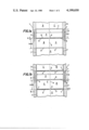
- FIG. 1a is a top plan view of a portion of a continuous web or paper strip made in accordance with the invention
- FIG. 1b is a bottom plan view of the embodiment shown in FIG. 1a;
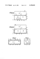
- FIG. 2a is a top plan view of a single strip element comprising a top or first invoice portion and a bottom or second cover portion as separated from the web or continuous strip of FIGS. 1a and 1b;
- FIG. 2b is a bottom plan view of the strip element shown in FIG. 2a;
- FIG. 3 is a bottom plan view of the inside of the strip element shown in FIGS. 2a and 2b after it has been folded in accordance with the invention.
- FIG. 4 is a top plan view of the completely folded cover with invoice included formed by the strip element shown in FIG. 3.
- a continuous strip generally designated 1 comprises a front face 1a seen in FIG. 1a, and a back face 1b seen in FIG. 1b.
- strip 1 is designed to form a plurality of covers, each including a first part which serves as an invoice for the payment of a public service, as, for instance, telephone, water, gas, etc.
- a series of aligned holes 2 is provided designed to engage means known per se for guiding and dragging the strip 1 into the apparatus provided to supply the data to be reproduced on said strip 1.
- the strip 1 is provided with a first plurality of transverse tear lines 3, which are spaced away from each other at a predetermined distance "2h+3d", where "h” is the height of the first part A of each strip element designed to form that part of a cover which will serve as invoice or the like, and “d” is the width of the closure edges of the cover to be obtained from each strip element.
- a longitudinal or center line 4 is provided along which will be performed the second bending step of each strip element, while transverse lines 5 are provided along which in each strip element the first bending is performed, each line 5 subdividing a strip element, which is formed between two adjacent lines 3, into two parts, i.e.
- lines 6 are arranged on the first or short part of each strip element so as to define the lower edge of the invoice A, and to be spaced apart from the adjacent bending line 5 by a distance "d".
- a transverse band E is defined between lines 5 and 6 which has a height equal to "d".
- This band E is a part of the first short part A of the strip element. It is to be pointed out that the tearing line 6 always remains in the inside of the cover so as to fulfil the U.P.U. requirements.
- the band E is coated with an adhesive only on a portion of its width so as to leave small longitudinal edge portions free for a few millimeters.
- the adhesive is applied only for a distance of about 1.5 cm from the folding line 4 so as not to create a zone of an increased thickness near the line 4 after the folding, and so that a control detector associated with a bending machine will not misinterpret the single cover as being more than two overlapping paper layers. As a result thereof a central area P will be provided on the band E without adhesive.
- longitudinal slots 7 are cut. These are substantially equally spaced apart from the longitudinal edges of the strip 1.
- the inner edges of the slots 7 define the length L of the invoice A.
- the slots 7 will have a width substantially equal to "d”.
- On the face 1b of the strip 1 is applied the same adhesive, used to form the adhesive band applied on E, the adhesive being applied on a transverse band D of a height "d" adjacent each line 3, but provided on the long or second part of each strip element.
- the adhesive will be applied only in the innermost portion of the band D so as to leave short longitudinal outer edge portions of the band D without adhesive for the same purpose as specified with reference to the adhesive applied on the band E.
- Identically on the band D at both sides of the line 4 will be provided an area Q without adhesive for the same purpose as the area P on the band E.
- the adhesive is also missing at the end portions or areas T of the band D in order to provide air passages to let the air entrapped between the inner walls of the cover during the folding and bonding steps flow freely out from between the cover halves.
- the adhesive on the longitudinal bands D', positioned in alternating fashion with the slots 7.
- the adhesive is applied only up to a distance greater than "d" from the ends of the slots 7, preferably at a distance of about 1.5 cm, so as to leave an area S free of adhesive, said adhesive being also in this case applied in such a manner that it cannot reach the edges of the bands D'.
- the areas S without adhesive have two functions.
- One is to form in the cover, in its closed condition, two gripping limbs for the opening of the cover since an adhesive of self-bonding, but non-permanent type is used, and the other function is to permit the preparation of the strip 1 which has previously been bent in a bellow or accordeon disposition according to a common preparation method of the paper strip for the aforementioned purposes.
- Each strip 1 is prepared in such a bellows form, each folded portion of the bellows being bounded by a line 3 so that each folded portion preferably, forms one strip element.
- the transverse adhesive bands D and E can never overlap each other as well as the longitudinal bands D', owing to the presence of the areas S without adhesive. It is to be pointed out that in the event the part A, for particular intended purposes, must be separated into two halves along the centre line 4, the portion of the line 4 which passes through the part A and the band E will be substituted with a tear line which extends beyond the line 3 by about 2 mm so as to have a height of h+d+2 mm. This is done, if the invoice embodies also a form for the payment thereof in A/C, and this tear line also promotes a correct folding of the cover along the centre line 4.
- the face 1a of the strip 1 will be printed or reproduced in any other suitable manner, in particular on the part A, all the informations or indications relative to an invoice in general, as well as framings defining the spaces to receive the various data and the indications of the destinations thereof. Then the computer or the like reproduces in sequence the data relative to each user, as for instance, the data of the preceding reading of the counter, those of the last reading, the consumption amount, the amount of the taxes and, however, all the data which normally are reproduced on an invoice, which is "per se" of a well known type, while on the opposite face of each strip element will be printed the various instructions to the users which the Utility Company or the like usually provides. As seen in FIGS.
- the front surface 1a, of the portion B includes a framing 8 into which is written the addressee's address and on the same portion B will also be printed the name and address of the sender.
- the front surface 1a of the portion C other information may be printed to be sent to all the Service users, said information or communications being normally printed on separate sheets, which in the conventional covers have to be inserted, in turn, separately into the envelope together with the invoice.
- the continuous strip of this invention will be used as follows:
- the strip 1 is introduced into the machine provided to supply in sequence all data relative to a series of the Service users and this machine is suited to reproduce correctly said data onto the predetermined areas of each strip element without any possibility of misalignments.
- the strip 1 is then coveyed into a cutter of a conventional type which cuts away the longitudinal sides or longitudinal side portions of the strip 1 up to about the outer longitudinal edges of the slots 7.
- Successively the strip 1 is mechanically torn along the transverse lines 3 which have been made so as to be more easily torn than the tearing lines 6 so as to obtain strip lengths of the shape shown in FIGS. 2a and 2b.
- each strip element is mechanically bent along their transverse lines 5, causing each strip element to be folded so that the two portions of its back surface 1b overlap one another so that an "open" cover is thus obtained which, as viewed from its inside, is as shown in FIG. 3, where the main face 1a of the invoice A is seen, said invoice A at its lower part being now still joined with the band E.
- the bands D', D and D' extend the faces 1b of which are now in view as well as the face 1a of the band E which carry the adhesive means with the exception of the areas P,Q,S and T. Now it will be sufficient to bend the cover along the centre line 4.
- the bending machine is also able to apply a pressure to cause the half bands E, the half bands D and the two side bands D' to be bound to each other, thus obtaining a closed cover (FIG. 4) which can be easily opened by pulling the adherent peripheral closure limbs at s, apart by engaging the portions S which are without adhesive and which act as gripping limbs.
- the so obtained article can be used as a closed cover, which could however, be easily opened so as to take advantage of a reduced postal tax.
- the user when the user receives the cover, he can easily open the cover and separate the invoice A along the tearing line 6 from the remaining portions of the cover. Afterwards the invoice A becomes a conventional invoice, which could be paid in A/C by any Post Office, keeping a predetermined portion as receipt.
- the cover when the cover is closed, the user's address is reproduced in the position required by the U.P.U. Rules so it can be easily read by any electronical optical reader so that there is no risk that the cover can be rejected by the automation apparatus of the Postal Service.
- the covers can get stuck to other covers, with which they may come into contact, as often occurs using the conventional envelopes or covers, the peripheral edge portions of which may be raised or separated from one another so that a cover can get partially stuck with another.
- each left slot 7 obtained by a punching machine serves also to provide a right support means for an optical reader, for performing a checking operation by the Service Body. This is done after the payment at the post Office, using the form associated with the invoice, has been made by the user and a portion of the form has been returned to said Service Body.
- the invention comprises a continuous strip or web of paper or the like generally designated 1 which is divided into a plurality of invoice-cover combinations which are individually mailable and include machine-readable address indicia, the web 1 including a longitudinal side portion defined on either longitudinal side of the continuous web which each includes a plurality of longitudinally-spaced perforations 2.
- a plurality of equally-spaced transverse tear lines 3 are defined across the continuous web by weakness lines which can be folded and later torn to separate the web.
- Strip elements are defined between each adjacent pair of transverse tear lines 3 and each strip element includes a pair of longitudinal slots 7 extending longitudinally across a portion of each strip element and adjoining each longitudinal side portion of the web as a whole. Each longitudinal slot has a transverse width substantially equal to lower case d.
- Each strip element comprises an invoice portion A defined between each pair of the longitudinal slots 7, and a cover portion C, B.
- the invoice portion A and the cover portion C, B, are separated by the transverse fold line 5.
- Each invoice portion A has a longitudinal height equal to h plus d, where d is the longitudinal width of a first band E which is adjacent the fold line 5.
- the height h is the longitudinal height of the invoice portion A on which a data is applied.
- Each cover portion C, D has a longitudinal height equal to h plus 2d with a second band D having a longitudinal width d defined on the cover portion adjacent one of the transverse tear lines 3.
- the transverse width of each invoice portion A is equal to L which is the distance between the pair of adjacent longitudinal slots 7.
- the transverse width of each cover portion with the longitudinal side portion cut away is equal to L plus 2d and includes two-third bands D' of width d defined on either transverse side thereof.
- the continuous web 1 has a top face 1a and a bottom face 1b and includes a central longitudinal fold line 4 defined therein.
- the longitudinal fold line 4 as with the transverse fold line 5 may be imaginary or printed.
- the top and bottom face of the continuous web defines the top and bottom faces of each invoice and cover portion with the data and machine readable address indicia being applied to the top faces of the invoice and cover portions respectively.
- a self-adhering adhesive is applied to at least the major portion of the first band E on the top side 1a thereof and to at least the major portion of the second and third bands on the bottom face thereof.
- Each of the first, second and third bands have one part on one side of the transverse fold line 4 and another part on the other side of the transverse fold line 4. It should be noted that the strip elements are arranged with alternating invoice and cover portions so that the data and address can be applied to the web in a single orientation as the web is fed through the printing machine.
Landscapes
- Making Paper Articles (AREA)
- Credit Cards Or The Like (AREA)
- Laminated Bodies (AREA)
Applications Claiming Priority (4)
| Application Number | Priority Date | Filing Date | Title |
|---|---|---|---|
| IT48616A/77 | 1977-03-24 | ||
| IT4861677A IT1021151B (it) | 1977-03-24 | 1977-03-24 | Striscia continua di carta o simile per la compilazione automatizzata di bollette certificati o simili trasformabili in plichi chiusi |
| IT49571A/77 | 1977-05-26 | ||
| IT4957177A IT1021226B (it) | 1977-05-26 | 1977-05-26 | Perfezionamenti alla striscia conti nua di carta o simile per la compila zione automatica di bollette o simili |
Publications (1)
| Publication Number | Publication Date |
|---|---|
| US4199630A true US4199630A (en) | 1980-04-22 |
Family
ID=26329339
Family Applications (1)
| Application Number | Title | Priority Date | Filing Date |
|---|---|---|---|
| US05/822,924 Expired - Lifetime US4199630A (en) | 1977-03-24 | 1977-08-08 | Continuous paper strip or the like to form invoices and the like transformable into closed covers |
Country Status (7)
| Country | Link |
|---|---|
| US (1) | US4199630A (fr) |
| BE (1) | BE894115Q (fr) |
| CH (1) | CH623518A5 (fr) |
| DE (1) | DE2737244C2 (fr) |
| FR (1) | FR2384680A1 (fr) |
| GB (1) | GB1590541A (fr) |
| NL (1) | NL178498C (fr) |
Cited By (15)
| Publication number | Priority date | Publication date | Assignee | Title |
|---|---|---|---|---|
| US4342418A (en) * | 1980-08-14 | 1982-08-03 | Luciano Meschi | Blank for the transmission of information having improved preglued sealing areas |
| US4726970A (en) * | 1986-08-19 | 1988-02-23 | Morrish Stephen C | Packaging employing computer paper |
| US4850612A (en) * | 1986-12-02 | 1989-07-25 | Instance David John | Labels and manufacture thereof |
| US4915288A (en) * | 1989-04-27 | 1990-04-10 | Avery International Corporation | Envelope with single peel-off backing sheet to facilitate printing and copying |
| US4927072A (en) * | 1986-09-25 | 1990-05-22 | Moore Business Forms, Inc. | Mailer |
| US4948028A (en) * | 1989-02-03 | 1990-08-14 | Avery International Corporation | Variable size envelope with single closure flap |
| US4981251A (en) * | 1986-09-25 | 1991-01-01 | Moore Business Forms, Inc. | Mailer |
| US5015319A (en) * | 1987-07-30 | 1991-05-14 | Richard Wilen | Programmable rack and system for making same |
| US5174494A (en) * | 1991-10-04 | 1992-12-29 | Moore Business Forms, Inc. | Bifold mailer with return envelope |
| US5360159A (en) * | 1991-08-15 | 1994-11-01 | Moore Business Forms, Inc. | Mailers and business form assemblies for producing mailers |
| US5398867A (en) * | 1992-11-27 | 1995-03-21 | Murphy; Kathleen M. | Combination paper and envelopes formed on a continuous paper web |
| US5407233A (en) * | 1987-07-30 | 1995-04-18 | Wilen; Richard | Magazine assembly |
| US20040130141A1 (en) * | 1999-04-15 | 2004-07-08 | Laser Substrates, Inc. | Multi-label mailing form including certified self-mailer |
| US20050006445A1 (en) * | 2002-05-31 | 2005-01-13 | Katz Robert E. | Inline manufactured crossfold package and method |
| US20070090173A1 (en) * | 2005-10-19 | 2007-04-26 | David Yost | Intermediate for Z-fold business mailer |
Families Citing this family (3)
| Publication number | Priority date | Publication date | Assignee | Title |
|---|---|---|---|---|
| IT8211575U1 (it) * | 1982-03-09 | 1983-09-09 | Conti Romano | Modulo ripiegabile ed incollabile per spedizione postal, con zone prive di preincollaggio |
| DE3426635A1 (de) * | 1983-12-12 | 1985-06-20 | Günter 7145 Markgröningen Baumann | Brief fuer werbezwecke |
| IT1206818B (it) * | 1987-05-28 | 1989-05-03 | Ilte Ind Libraria Tipografica | Un modulo per versamento in conto striscia continua di carta, per unacorrente postale ed un modulo di compilazione meccanografica riparti risposta ta in segmenti trasformabili in plichi chiusi, apribili, ed includenti |
Citations (8)
| Publication number | Priority date | Publication date | Assignee | Title |
|---|---|---|---|---|
| CH5634A (de) * | 1892-09-17 | 1893-02-15 | Merridew Frank Melville | Postbriefkarte mit Rückantwort |
| US786436A (en) * | 1904-08-30 | 1905-04-04 | William Goodman | Postal and commercial reply-card. |
| US2051711A (en) * | 1934-01-23 | 1936-08-18 | Us Envelope Co | Envelope |
| US2773638A (en) * | 1947-11-28 | 1956-12-11 | Henry R Krohn | Mailing article |
| CA776000A (en) * | 1968-01-16 | John H. Hayes, Jr. | Letter sheet | |
| US3523638A (en) * | 1967-04-28 | 1970-08-11 | Robert J Moonan | Mailer |
| US3837565A (en) * | 1972-02-15 | 1974-09-24 | E Johnsen | Rapid production envelope assemblies |
| US4023727A (en) * | 1976-01-26 | 1977-05-17 | Shade Information Systems, Inc. | Mailing envelope structure and method |
Family Cites Families (8)
| Publication number | Priority date | Publication date | Assignee | Title |
|---|---|---|---|---|
| US2517843A (en) * | 1947-04-21 | 1950-08-08 | Charles B Cochran | Combination advertising and return order blank |
| DE1787067U (de) * | 1959-02-09 | 1959-04-16 | Otto Schnug O H G Buchdruckere | Endlos-umschlaege-lohntueten mit selbstklebegummierung verschiedener art. |
| US3580488A (en) * | 1968-01-02 | 1971-05-25 | Stanley Komen | Continuous envelope |
| DE7013136U (de) * | 1970-04-10 | 1970-10-29 | Volk Inc Kurt H | Kombination aus briefbogen mit umschlag. |
| US3790068A (en) * | 1971-05-20 | 1974-02-05 | Us Envelope Co | Continuous form envelope assembly |
| FR2284532A1 (fr) * | 1974-09-11 | 1976-04-09 | Nicham Robert | Liasse-enveloppe d'expedition postale livree sous forme de bande continue |
| US3995808A (en) * | 1974-10-16 | 1976-12-07 | Gaf Corporation | Unit containing variable messages |
| IT1018601B (it) * | 1977-02-25 | 1977-10-20 | Atel Spa | Busta per corrispondenza in particolare di tipo amministrativo e procedimento per la sua formazione da foglio continuo includente la busta stessa ed il relativo contenuto |
-
1977
- 1977-08-01 GB GB32198/77A patent/GB1590541A/en not_active Expired
- 1977-08-02 CH CH960977A patent/CH623518A5/it not_active IP Right Cessation
- 1977-08-08 US US05/822,924 patent/US4199630A/en not_active Expired - Lifetime
- 1977-08-11 NL NLAANVRAGE7708878,A patent/NL178498C/xx not_active IP Right Cessation
- 1977-08-17 FR FR7725200A patent/FR2384680A1/fr active Granted
- 1977-08-18 DE DE2737244A patent/DE2737244C2/de not_active Expired
-
1982
- 1982-08-13 BE BE0/208816A patent/BE894115Q/fr not_active IP Right Cessation
Patent Citations (8)
| Publication number | Priority date | Publication date | Assignee | Title |
|---|---|---|---|---|
| CA776000A (en) * | 1968-01-16 | John H. Hayes, Jr. | Letter sheet | |
| CH5634A (de) * | 1892-09-17 | 1893-02-15 | Merridew Frank Melville | Postbriefkarte mit Rückantwort |
| US786436A (en) * | 1904-08-30 | 1905-04-04 | William Goodman | Postal and commercial reply-card. |
| US2051711A (en) * | 1934-01-23 | 1936-08-18 | Us Envelope Co | Envelope |
| US2773638A (en) * | 1947-11-28 | 1956-12-11 | Henry R Krohn | Mailing article |
| US3523638A (en) * | 1967-04-28 | 1970-08-11 | Robert J Moonan | Mailer |
| US3837565A (en) * | 1972-02-15 | 1974-09-24 | E Johnsen | Rapid production envelope assemblies |
| US4023727A (en) * | 1976-01-26 | 1977-05-17 | Shade Information Systems, Inc. | Mailing envelope structure and method |
Cited By (18)
| Publication number | Priority date | Publication date | Assignee | Title |
|---|---|---|---|---|
| US4342418A (en) * | 1980-08-14 | 1982-08-03 | Luciano Meschi | Blank for the transmission of information having improved preglued sealing areas |
| US4726970A (en) * | 1986-08-19 | 1988-02-23 | Morrish Stephen C | Packaging employing computer paper |
| US4927072A (en) * | 1986-09-25 | 1990-05-22 | Moore Business Forms, Inc. | Mailer |
| US4981251A (en) * | 1986-09-25 | 1991-01-01 | Moore Business Forms, Inc. | Mailer |
| US4850612A (en) * | 1986-12-02 | 1989-07-25 | Instance David John | Labels and manufacture thereof |
| US5407233A (en) * | 1987-07-30 | 1995-04-18 | Wilen; Richard | Magazine assembly |
| US5015319A (en) * | 1987-07-30 | 1991-05-14 | Richard Wilen | Programmable rack and system for making same |
| US4948028A (en) * | 1989-02-03 | 1990-08-14 | Avery International Corporation | Variable size envelope with single closure flap |
| US4915288A (en) * | 1989-04-27 | 1990-04-10 | Avery International Corporation | Envelope with single peel-off backing sheet to facilitate printing and copying |
| US5360159A (en) * | 1991-08-15 | 1994-11-01 | Moore Business Forms, Inc. | Mailers and business form assemblies for producing mailers |
| US5174494A (en) * | 1991-10-04 | 1992-12-29 | Moore Business Forms, Inc. | Bifold mailer with return envelope |
| US5398867A (en) * | 1992-11-27 | 1995-03-21 | Murphy; Kathleen M. | Combination paper and envelopes formed on a continuous paper web |
| US20040130141A1 (en) * | 1999-04-15 | 2004-07-08 | Laser Substrates, Inc. | Multi-label mailing form including certified self-mailer |
| US7357423B2 (en) * | 1999-04-15 | 2008-04-15 | Laser Substrates, Inc. | Multi-label mailing form including certified self-mailer |
| US20050006445A1 (en) * | 2002-05-31 | 2005-01-13 | Katz Robert E. | Inline manufactured crossfold package and method |
| US7090114B1 (en) * | 2002-05-31 | 2006-08-15 | Katz Robert E | Inline manufactured crossfold package and method |
| US20070090173A1 (en) * | 2005-10-19 | 2007-04-26 | David Yost | Intermediate for Z-fold business mailer |
| US7975904B2 (en) | 2005-10-19 | 2011-07-12 | Infoseal, Llc | Intermediate for Z-fold business mailer |
Also Published As
| Publication number | Publication date |
|---|---|
| FR2384680A1 (fr) | 1978-10-20 |
| GB1590541A (en) | 1981-06-03 |
| FR2384680B1 (fr) | 1982-05-28 |
| NL178498C (nl) | 1986-04-01 |
| NL178498B (nl) | 1985-11-01 |
| DE2737244C2 (de) | 1986-07-31 |
| DE2737244A1 (de) | 1978-09-28 |
| BE894115Q (fr) | 1982-12-01 |
| CH623518A5 (en) | 1981-06-15 |
| NL7708878A (nl) | 1978-09-26 |
Similar Documents
| Publication | Publication Date | Title |
|---|---|---|
| US4199630A (en) | Continuous paper strip or the like to form invoices and the like transformable into closed covers | |
| US3652007A (en) | Two-way mailing envelope | |
| CA1272747A (fr) | Depliant postal sous enveloppe contenant une enveloppe de retour et un bordereau de paiement | |
| CA1333708C (fr) | Enveloppe avec rabat detachable portant tous deux des images produites par un dispositif intelligent | |
| US4044942A (en) | Multiple mailing folder | |
| US4278199A (en) | Post card | |
| US4824142A (en) | Continuous business forms | |
| US2759658A (en) | Envelopes | |
| US4354631A (en) | Resealable envelope | |
| US1946751A (en) | Bank-check post-card folder | |
| US5464255A (en) | Folded business form with return envelope | |
| US6173888B1 (en) | Mailing form for non-impact printing | |
| US4632427A (en) | Combined mailer and return envelope | |
| IE54802B1 (en) | Postal module for confidential information | |
| US4454980A (en) | Return biller envelope book | |
| JPH02109855A (ja) | 内蔵形差込書郵送物 | |
| US3790193A (en) | Combination statement and check and method of making a negotiable check | |
| US6402022B1 (en) | Mailing form for non-impact printing | |
| CA1323617C (fr) | Enveloppe-reponse que l'on replie, a ouverture laterale et pouvant etre decachetee automatiquement | |
| US6409079B1 (en) | Print-to mail compatible, two-way self-contained mailer | |
| US6672624B2 (en) | Mailing form for non-impact printing | |
| US6412687B1 (en) | Pressure seal C-Z fold mailer with built-in return envelope | |
| US5172855A (en) | Continuous mailer form | |
| US5452851A (en) | Two-sheet self-mailer | |
| US5338068A (en) | Business form/receipt recording system |