US4208887A - Suction accumulator having heat exchanger - Google Patents
Suction accumulator having heat exchanger Download PDFInfo
- Publication number
- US4208887A US4208887A US06/005,140 US514079A US4208887A US 4208887 A US4208887 A US 4208887A US 514079 A US514079 A US 514079A US 4208887 A US4208887 A US 4208887A
- Authority
- US
- United States
- Prior art keywords
- passageway
- vessel
- fluid
- suction accumulator
- weir member
- Prior art date
- Legal status (The legal status is an assumption and is not a legal conclusion. Google has not performed a legal analysis and makes no representation as to the accuracy of the status listed.)
- Expired - Lifetime
Links
Images


Classifications
-
- F—MECHANICAL ENGINEERING; LIGHTING; HEATING; WEAPONS; BLASTING
- F28—HEAT EXCHANGE IN GENERAL
- F28D—HEAT-EXCHANGE APPARATUS, NOT PROVIDED FOR IN ANOTHER SUBCLASS, IN WHICH THE HEAT-EXCHANGE MEDIA DO NOT COME INTO DIRECT CONTACT
- F28D9/00—Heat-exchange apparatus having stationary plate-like or laminated conduit assemblies for both heat-exchange media, the media being in contact with different sides of a conduit wall
- F28D9/0031—Heat-exchange apparatus having stationary plate-like or laminated conduit assemblies for both heat-exchange media, the media being in contact with different sides of a conduit wall the conduits for one heat-exchange medium being formed by paired plates touching each other
-
- F—MECHANICAL ENGINEERING; LIGHTING; HEATING; WEAPONS; BLASTING
- F25—REFRIGERATION OR COOLING; COMBINED HEATING AND REFRIGERATION SYSTEMS; HEAT PUMP SYSTEMS; MANUFACTURE OR STORAGE OF ICE; LIQUEFACTION SOLIDIFICATION OF GASES
- F25B—REFRIGERATION MACHINES, PLANTS OR SYSTEMS; COMBINED HEATING AND REFRIGERATION SYSTEMS; HEAT PUMP SYSTEMS
- F25B40/00—Subcoolers, desuperheaters or superheaters
-
- F—MECHANICAL ENGINEERING; LIGHTING; HEATING; WEAPONS; BLASTING
- F25—REFRIGERATION OR COOLING; COMBINED HEATING AND REFRIGERATION SYSTEMS; HEAT PUMP SYSTEMS; MANUFACTURE OR STORAGE OF ICE; LIQUEFACTION SOLIDIFICATION OF GASES
- F25B—REFRIGERATION MACHINES, PLANTS OR SYSTEMS; COMBINED HEATING AND REFRIGERATION SYSTEMS; HEAT PUMP SYSTEMS
- F25B43/00—Arrangements for separating or purifying gases or liquids; Arrangements for vaporising the residuum of liquid refrigerant, e.g. by heat
- F25B43/006—Accumulators
-
- F—MECHANICAL ENGINEERING; LIGHTING; HEATING; WEAPONS; BLASTING
- F25—REFRIGERATION OR COOLING; COMBINED HEATING AND REFRIGERATION SYSTEMS; HEAT PUMP SYSTEMS; MANUFACTURE OR STORAGE OF ICE; LIQUEFACTION SOLIDIFICATION OF GASES
- F25B—REFRIGERATION MACHINES, PLANTS OR SYSTEMS; COMBINED HEATING AND REFRIGERATION SYSTEMS; HEAT PUMP SYSTEMS
- F25B2400/00—Component parts or details not otherwise provided for in this subclass
- F25B2400/05—Compression system with heat exchange between particular parts of the system
- F25B2400/051—Compression system with heat exchange between particular parts of the system between the accumulator and another part of the cycle
Definitions
- the present invention relates to a heat exchanger within a suction accumulator particularly adapted for use in a refrigeration system.
- compressors used in refrigeration systems are designed for the compression of gaseous refrigerant. Under some circumstances, however, a certain amount of liquid may flow from the evaporator into the inlet of the compressor so as to cause a condition known as slugging. If this occurs after the system is shut down, large quantities of condensed refrigerant return through the suction line to the crankcase of the compressor, and when the compressor is restarted, the large quantity of liquid refrigerant present therein results in abnormally high pressures which frequently causes blown gaskets, broken valves, and the like.
- Suction accumulators prevent this from occurring by providing a reservoir for the liquid refrigerant at the inlet to the compressor, and serve to separate the gaseous and liquid components of the refrigerant so that only the gaseous component and a controlled amount of liquid is admitted to the inlet of the compressor.
- One type of accumulator comprises a vessel having a generally U-shaped tube mounted therein, wherein one end of the tube is connected to an outlet tube leading from the vessel, and the other end of which is open to the interior of the vessel. As the incoming liquid refrigerant flows into the vessel, it collects in the bottom thereof whereas the gaseous component is carried off through the tube to the outlet.
- This type of suction accumulator is disclosed in U.S. Pat. No. 3,420,071, for example.
- suction accumulator comprises a storage vessel having a generally vertical weir member located between the vessel inlet and outlet and which forms, in conjunction with the confronting walls of the vessel, a storage reservoir and an outlet flume on opposite sides of the weir.
- the vessel fluid inlet is located on the reservoir side of the weir member and the fluid outlet on the flume side thereof.
- the prior art teaches providing a heat exchanger coil within the suction accumulator so that the relatively warm refrigerant from the condenser can be cooled through heat exchange with the relatively cool liquid refrigerant in the accumulator.
- the heat exchanger simply comprises a coil disposed within the accumulator. In other cases the coil is in close proximity or in contact with the gaseous refrigerant tube, or mounted in a more remote location. Such an arrangement results in an inefficient transfer of heat between the respective fluids, and causes manufacturing problems.
- Prior art patents disclosing such heat exchangers include U.S. Pat. Nos. 2,393,854, 2,467,078, 2,472,729, 2,530,648, 3,021,693, 2,270,934, and 3,765,192.
- the suction accumulator heat exchanger of the present invention overcomes the disadvantages of the prior art by virtue of the fact that the heat exchange fluid passageway is formed as a jacket around at least a portion of the gaseous refrigerant passageway, thereby resulting in optimum heat exchange between the respective fluids.
- the heat exchange passageway is formed as an annular passageway around the U-shaped gaseous refrigerant conduit.
- the heat exchange passageway is formed within the weir member, which divides the vessel into the storage and outlet flume portions. In the latter embodiment, easily manufactured and assembled metal stampings can be utilized for the weir-heat exchanger.
- the advantage of arrangement described above is that the refrigerant flowing through the heat exchange passageway comes into direct heat exchange contact both with the incoming liquid and the gaseous refrigerant within the storage portion of the vessel, and with the gaseous refrigerant flowing through the outlet flume or U-shaped tube, as the case may be.
- the heat exchanger of the present invention is always subjected to moving refrigerant, either gaseous or liquid.
- the present invention relates to a heat exchanger integrated with a suction accumulator including a storage vessel having a refrigerant inlet, and means defining a first fluid passageway in the vessel having an inlet in communication with the interior of the vessel and an outlet extending out of the vessel.
- the heat exchanger comprises a jacket disposed over at least a portion of the surface of the means defining a first fluid passageway and being spaced therefrom so as to form a second fluid passageway between the jacket and the surface.
- the second fluid passageway is sealed from a first passageway and from the interior of the vessel and has a fluid inlet and a fluid outlet each leading to the exterior of the vessel.
- a still further object of the present invention is to provide a suction accumulator heat exchanger which is simple in design and economical to manufacture.
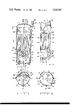
- FIG. 1 is a partially sectioned elevational view of one embodiment of the suction accumulator and heat exchanger according to the present invention
- FIG. 2 is a perspective view of the weir member of the suction accumulator and heat exchanger of FIG. 1;
- FIG. 3 is a sectional view taken along line 3--3 of FIG. 1;
- FIG. 4 is a sectional view taken along line 4--4 of FIG. 1;
- FIG. 5 is an elevational view of the suction accumulator and heat exchanger with portions of the outer vessel cut away;
- FIG. 6 is a longitudinal sectional view of a second embodiment of the invention.
- FIG. 7 is a transverse sectional view taken along line 7--7 of FIG. 6;
- FIG. 8 is a fragmentary sectional view taken along line 8--8 of FIG. 7;
- FIG. 9 is a fragmentary sectional view taken along line 9--9 of FIG. 7;
- FIG. 10 is a sectional view taken along line 10--10 of FIG. 6.
- suction accumulator 12 comprises a pressure vessel 14, which is preferably formed of two identical half sections 16 and 18 produced from sheet metal by a stamping process.
- Vessel 14 has a generally cylindrical midsection with convex top 20 and bottom 22 ends.
- sections 16 and 18 are joined together by overlapping seams 24 and 26, which are copper brazed in a hydrogen atmosphere furnace, thereby creating a strong, fluid tight seam.
- the seams 24 and 26 extend lengthwise of the vessel 14 and lie within a plane coinciding with the longitudinal axis of the vessel, which is preferably vertically disposed when the suction accumulator 12 is installed.
- a vertically disposed outlet pipe fitting 26 is sealed in an extrusion-pierced, collared aperture in the top portion of vessel section 16, with the outer end 28 thereof being enlarged to form the female member of a sweat connection with the suction line of a mechanical compressor (not shown).
- Inlet fitting 30 is also received within an extrusion-pierced, collared aperture extending through a bulbous portion 32 of vessel wall section 18, and is horizontally disposed and tangentially positioned with respect to the arcuate inner surface 34 of vessel section vessel section 18. This is so that the incoming refrigerant will impinge on a surface which is shaped to cause the fluid to flow round the vessel axis with a swirling motion.
- Weir member 36 is a non-planar sheet metal plate formed by a stamping process, and is so formed that when it is positioned vertically within vessel 14, its bottom edge 40 and side edges 42 and 44 sealingly attach to the inner surface of the vessel as by copper brazing.
- weir member 36 is wholly contained within one side section 16 of vessel 14, and is shaped such that a generally U-shaped outlet flume having two upright passageways 46 and 48 are formed between it and vessel section 16.
- Passageways 46 and 48 are formed by two generally planar rectangular panel sections 50 and 52 integrally connected together along a vertical ridge 54 which abuts the vessel wall 56.
- Panel sections 50 and 52 terminate above the bottom end of the vessel but have integrally connected triangular panel extensions 58 and 60 which are angled away from the vessel wall and integrally joined together in the shape of a half pyramid.
- the wing sections 62 and 64 and panel extensions 58 and 60 jointly define the inner wall of the connecting leg 61 of the U-shaped outlet flume.
- weir member 36 In addition to defining the outlet flume, weir member 36 also defines storage reservoir 66, which is formed between weir member 36 and the inner wall 34 of vessel half section 18.
- a liquid bleed-through aperture 68 having a diameter of 1/16", for example, is located at the bottom end of weir member 36 in wing section 62.
- aperture 68 and the area around it is recessed away from the reservoir 66 so that when a screen 70 is welded over the recessed area, a plurality of screen openings are available to the recessed area and will prevent clogging of the fluid path leading from one side of weir member 36 to the other.
- the top portion 72 of outlet flume leg 48 is enlarged by forming a bulbous section 74, which extends under and slightly beyond the vertically disposed outlet fitting 26.
- this bulbous section 74 is streamlined as much as possible so that the incoming refrigerant liquid does not splash excessively in a vertical direction either upwardly or downwardly.
- the top of panel 50 defining the inlet leg 46 of the flume has a narrow lip 76 which extends over an edge of a horizontally disposed baffle plate 78.
- a vertically projecting twist tab 80 is provided on the top edge of outlet leg panel 52 to locate and hold baffle plate 78 in position on weir member 36 during assembly.
- Baffle plate 78 is shaped to conform to the cross sectional shape of the inside of vessel 14 level with the top of weir member 36 but excluding the area over the top of the inlet leg 46 of the flume which is left open.
- a large diameter opening 82 adjacent the center of baffle plate 78 forms the primary fluid outlet from the reservoir 66 to the flume inlet leg 46.
- this opening is not centered on the vessel axis but is offset towards the inlet fitting 30 so that the entire opening is upstream from the inlet to reservoir 66.
- the area of opening 82 as well as the cross sectional areas of the outlet flume are sized so that they are all larger than the area of the vessel inlet or outlet.
- a second aperture 84 extends through baffle plate 78 for the purposes of pressure equalization. Up to this point, the suction accumulator 12 described is identical to that disclosed in U.S. Pat. No. 4,041,728.
- the heat exchanger according to the present invention is formed against one side 86 of weir member 36 and comprises a non-planar sheet metal stamping, which is generally in the shape of an angled piece of sheet metal 88 having raised portions, which define the tortuous fluid passageways for the liquid refrigerant flowing therethrough. More specifically, sections 90 and 92 lie in respective planes which intersect along the fold line 94. Ridges 96 and 98, which extend from one edge of section 90 to the opposite edge of section 92, form a pair of generally parallel, tortuous fluid passage ways leading from the raised manifold 100 in communication with inlet 102 to the raised manifold 104 in communication with outlet 106.
- planar portions of sections 90 and 92 and the respectively coplanar portions between raised ridges 96 and 98 are copper brazed against the facing side of weir member 36.
- Inlet 102 and outlet 106 extend through half section 18 for connection to the condenser outlet (not shown) and evaporator inlet (not shown), respectively.
- the incoming refrigerant liquid which may be substantially liquid, substantially gaseous, or a mixture of liquid and gas including some lubricating oil, enters vessel 14 through the tangentially disposed inlet fitting 30 at the top of the reservoir 66 immediately beneath the baffle plate 78.
- the incoming refrigerant is projected against the confronting cylindrical surface 34 of the vessel 14 and caused to flow around the vessel in a generally circular or helical path, past the angularly disposed weir plate 36 and the similarly angularly disposed heat exchanger surface 88, and around the remaining cylindrical section of the vessel 14.
- the swirling action of the liquid-gaseous refrigerant creates a vortex in the reservoir 66 and slings the heavier liquid portion of the refrigerant toward the outer wall of the reservoir 66 away from the vicinity of the opening 88 in baffle 78.
- the lighter, relatively dry refrigerant gas in the vortex area is free to pass out of the reservoir 66 via opening 82 and enter the upper chamber of the accumulator 12 with a minimum of pressure drop.
- the liquid is temporarily retained in reservoir 66 as the gaseous portion flows out through the opening 82, then over the top of weir member 36 down flume inlet leg 46, across connecting leg 61, up flume outlet leg 48 and then vertically out of the vessel 14 through outlet fitting 28.
- the gaseous refrigerant first contacts the confronting side 88 of the heat exchanger while it is in the reservoir 66, and then contacts panel sections 50 and 52 and triangular extensions 58 and 60 of weir member 36, as it flows through the outlet flume. It will be appreciated that the panel sections 50 and 52 of weir member 36 form the rear walls for the heat exchange passageways. This arrangement permits the gaseous component of the refrigerant to come into direct heat exchange contact with the refrigerant flowing through the heat exchanger on both sides of weir member 36.
- the metering aperture 68 in conjunction with the pressure differential existing between the reservoir 66 and the outlet flume induces a metered flow of liquid lubricant into the gaseous refrigerant stream flowing through the flume, thereby ensuring that the lubricant is continually fed from the accumulator 12 to the compressor.
- the heat exchange inlet 102 connects to the condenser outlet, and the heat exchange outlet 106 connects to the inlet of the evaporator.
- the refrigerant flowing through the heat exchanger which, as it will be noted, flows against the flow of incoming refrigerant to the suction accumulator 12, will be cooled. Additionally, the refrigerant flowing through the accumulator 12 will be heated, thereby resulting in more efficient operation of the compressor.
- FIGS. 6-10 a modified form of the suction accumulator and heat exchanger of the present invention will be described.
- the accumulator 108 comprises a vessel 110 having a cylindrical midsection 112 and end caps 114 and 116, the latter having a mounting lug 118.
- Refrigerant inlet fitting 120 and outlet fitting 122 are received in suitably dimensioned openings in upper end cap 114 and are copper brazed thereto.
- Baffle plate 124 is brazed to midsection 112 and is cut away to form a pair of arcuate spaces 126 and 128 between it and the inner wall 130 of vessel midsection 112.
- a raised ridge 132 serves to deflect the incoming refrigerant from inlet fitting 120 toward the inner wall 130 of vessel midsection 112 and toward openings 126 and 128.
- partition member 134 Received within the lower portion of vessel 110 and brazed to vessel midsection 112 is a partition member 134 having a bleed-through orifice 136 formed therein. Also formed in partition member 134 are a pair of pierced and drawn openings 138 and 140, which extend upwardly as shown in FIG. 6. A screen 142 is welded to partition member 124 and prevents bleed-through orifice 136 from becoming clogged.
- a pair of vertically oriented tubes 144 and 146 are positioned around and brazed to drawn openings 140 and 138, respectively.
- Inlet tube 146 has a flared top 148, and the top 150 of tube 144 is drawn down so that it may be snugly received within outlet fitting 122.
- An opening 152 in tube 144 provides for pressure equalization between tube 144 and the interior of vessel 110.
- the heat exchanger of this embodiment of the invention is formed by a pair of tubes 154 and 156 concentrically positioned around tubes 144 and 146, respectively, such that a pair of annular passageways 158 and 160 are formed therebetween.
- the upper ends 162 and 164 of tubes 154 and 156 are drawn down into snug engagement with tubes 144 and 146 and brazed thereto.
- a flange member 166 having openings 168 and 170 is brazed to partition member 134 and to the lower ends of outer tubes 154 and 156.
- a pass over duct 172 is formed between annular heat exchange passageways 158 and 160.
- a completely sealed heat exchange passageway is formed between the suction accumulator tubes 144 and 146 and partition member 134 and outer tubes 154 and 156 and flange member 166.
- An inlet tube 173 is brazed to an appropriate fitting portion 174 on tube 154 and is also brazed at its other end to inlet fitting 176.
- the outlet tube 178 for the heat exchanger is brazed to a fitting portion 180 on tube 156 and is brazed at its other end to heat exchange outlet fitting 182.
- the heat exchange system is completely sealed from the accumulator system so that no intermixing of fluids is possible.
- the gaseous refrigerant rises and passes into tube 146 whereupon it flows downwardly into the manifold 184 formed between partition member 134 and end cap 116. After picking up the proper amount of lubricant, which flows into manifold 184 through bleed-through orifice 136, the gaseous refrigerant flows upwardly through tube 144 and out outlet fitting 122.
- the heat exchange refrigerant from the outlet of the condenser flows in through inlet fitting 176 through tube 173 into the annular passageway 158 formed between tubes 154 and 144. It flows downwardly into the space between partition member 134 and flange member 166, across duct 172, and upwardly through the annular passageway 160 formed between tubes 146 and 156. From there it flows out through tube 178 and outlet fitting 182 to the inlet of the evaporator (not shown). As can be seen, the heat exchange liquid flows in the opposite direction of the flow of gaseous refrigerant in the suction accumulator. This results in the most efficient transfer of heat from the refrigerant in the suction accumulator system to the refrigerant in the closed heat exchange system.
Landscapes
- Engineering & Computer Science (AREA)
- Physics & Mathematics (AREA)
- Mechanical Engineering (AREA)
- Thermal Sciences (AREA)
- General Engineering & Computer Science (AREA)
- Chemical & Material Sciences (AREA)
- Analytical Chemistry (AREA)
- Power Engineering (AREA)
- Heat-Exchange Devices With Radiators And Conduit Assemblies (AREA)
Priority Applications (2)
| Application Number | Priority Date | Filing Date | Title |
|---|---|---|---|
| US06/005,140 US4208887A (en) | 1979-01-22 | 1979-01-22 | Suction accumulator having heat exchanger |
| CA341,131A CA1107086A (fr) | 1979-01-22 | 1979-12-04 | Accumulateur d'aspiration avec echangeur de chaleur |
Applications Claiming Priority (1)
| Application Number | Priority Date | Filing Date | Title |
|---|---|---|---|
| US06/005,140 US4208887A (en) | 1979-01-22 | 1979-01-22 | Suction accumulator having heat exchanger |
Publications (1)
| Publication Number | Publication Date |
|---|---|
| US4208887A true US4208887A (en) | 1980-06-24 |
Family
ID=21714382
Family Applications (1)
| Application Number | Title | Priority Date | Filing Date |
|---|---|---|---|
| US06/005,140 Expired - Lifetime US4208887A (en) | 1979-01-22 | 1979-01-22 | Suction accumulator having heat exchanger |
Country Status (2)
| Country | Link |
|---|---|
| US (1) | US4208887A (fr) |
| CA (1) | CA1107086A (fr) |
Cited By (21)
| Publication number | Priority date | Publication date | Assignee | Title |
|---|---|---|---|---|
| EP0071062A1 (fr) * | 1981-07-23 | 1983-02-09 | Giuseppe Tuberoso | Réservoir avec fonction multiple pour un fluide thermo-dynamique |
| US4458505A (en) * | 1983-03-25 | 1984-07-10 | Parker-Hannifin Corporation | Suction line accumulator |
| FR2559555A1 (fr) * | 1984-02-10 | 1985-08-16 | Zimmern Bernard | Dispositif de lubrification pour machine a gaz liquefiable |
| EP0143013A3 (fr) * | 1983-09-16 | 1986-01-08 | Pactole S.A. | Procédé et dispositif de surchauffe d'un fluide frigorifique |
| US4589826A (en) * | 1983-04-14 | 1986-05-20 | Bernard Zimmern | Method of lubricating bearings of a machine handling liquefiable gas |
| US4627247A (en) * | 1986-03-21 | 1986-12-09 | Tecumseh Products Company | Suction accumulator |
| US4651540A (en) * | 1986-03-21 | 1987-03-24 | Tecumseh Products Company | Suction accumulator including an entrance baffle |
| EP0349704A1 (fr) * | 1988-07-05 | 1990-01-10 | Tecumseh Products Company | Accumulateur d'aspiration à collecteur d'impuretés |
| US5471854A (en) * | 1994-06-16 | 1995-12-05 | Automotive Fluid Systems, Inc. | Accumulator for an air conditioning system |
| US5701758A (en) * | 1996-01-30 | 1997-12-30 | Haramoto; Cary | Refrigeration system accumulating vessel having a brazed, metal-clad deflector |
| US5899091A (en) * | 1997-12-15 | 1999-05-04 | Carrier Corporation | Refrigeration system with integrated economizer/oil cooler |
| EP0924478A3 (fr) * | 1997-12-15 | 2000-03-22 | Carrier Corporation | Système frigorifique avec échangeur de chaleur intégré pour le refroidissement d'huile |
| US6058727A (en) * | 1997-12-19 | 2000-05-09 | Carrier Corporation | Refrigeration system with integrated oil cooling heat exchanger |
| EP0905459A3 (fr) * | 1997-09-25 | 2000-10-11 | Hansa Metallwerke Ag | Accumulateur pour système de climatisation de type à orifice, en particulier pour des systèmes de climatisation de véhicule |
| US6311514B1 (en) * | 2000-04-07 | 2001-11-06 | Automotive Fluid Systems, Inc. | Refrigeration accumulator having a matrix wall structure |
| GB2374400A (en) * | 2000-12-29 | 2002-10-16 | Visteon Global Tech Inc | Accumulator with internal heat exchanger |
| US6751983B1 (en) * | 1999-09-20 | 2004-06-22 | Behr Gmbh & Co. | Air conditioning unit with an inner heat transfer unit |
| US20050081559A1 (en) * | 2003-10-20 | 2005-04-21 | Mcgregor Ian A.N. | Accumulator with pickup tube |
| US20060032268A1 (en) * | 2004-08-16 | 2006-02-16 | Cole Robert G | Refrigeration capillary tube inside suction line assembly |
| US20060260354A1 (en) * | 2005-04-25 | 2006-11-23 | Matsushita Electric Industrial Co., Ltd. | Refrigeration cycle apparatus |
| US11214126B2 (en) * | 2017-05-02 | 2022-01-04 | Hanon Systems | Air conditioning system of a motor vehicle and method for operating the air conditioning system |
Citations (10)
| Publication number | Priority date | Publication date | Assignee | Title |
|---|---|---|---|---|
| US2270934A (en) * | 1939-10-13 | 1942-01-27 | Jr Edward F Dickieson | Control for refrigerating devices |
| US2393854A (en) * | 1942-01-31 | 1946-01-29 | Elizabeth C Carpenter | Feed control for liquid refrigerant |
| US2467078A (en) * | 1946-02-11 | 1949-04-12 | Harry Alter Company | Combination accumulator, metering tube, and heat exchanger for refrigeration systems |
| US2472729A (en) * | 1940-04-11 | 1949-06-07 | Outboard Marine & Mfg Co | Refrigeration system |
| US2530648A (en) * | 1946-09-26 | 1950-11-21 | Harry Alter Company | Combination accumulator, heat exchanger, and metering device for refrigerating systems |
| US3021693A (en) * | 1959-05-21 | 1962-02-20 | Mcquay Inc | Hot gas defrosting refrigerating apparatus |
| US3621673A (en) * | 1969-12-08 | 1971-11-23 | Trane Co | Air-conditioning system with combined chiller and accumulator |
| US3651657A (en) * | 1970-01-26 | 1972-03-28 | Edward W Bottum | Air conditioning system with suction accumulator |
| US3765192A (en) * | 1972-08-17 | 1973-10-16 | D Root | Evaporator and/or condenser for refrigeration or heat pump systems |
| US3872687A (en) * | 1969-07-11 | 1975-03-25 | Refrigeration Research | Vehicle air conditioning system |
-
1979
- 1979-01-22 US US06/005,140 patent/US4208887A/en not_active Expired - Lifetime
- 1979-12-04 CA CA341,131A patent/CA1107086A/fr not_active Expired
Patent Citations (10)
| Publication number | Priority date | Publication date | Assignee | Title |
|---|---|---|---|---|
| US2270934A (en) * | 1939-10-13 | 1942-01-27 | Jr Edward F Dickieson | Control for refrigerating devices |
| US2472729A (en) * | 1940-04-11 | 1949-06-07 | Outboard Marine & Mfg Co | Refrigeration system |
| US2393854A (en) * | 1942-01-31 | 1946-01-29 | Elizabeth C Carpenter | Feed control for liquid refrigerant |
| US2467078A (en) * | 1946-02-11 | 1949-04-12 | Harry Alter Company | Combination accumulator, metering tube, and heat exchanger for refrigeration systems |
| US2530648A (en) * | 1946-09-26 | 1950-11-21 | Harry Alter Company | Combination accumulator, heat exchanger, and metering device for refrigerating systems |
| US3021693A (en) * | 1959-05-21 | 1962-02-20 | Mcquay Inc | Hot gas defrosting refrigerating apparatus |
| US3872687A (en) * | 1969-07-11 | 1975-03-25 | Refrigeration Research | Vehicle air conditioning system |
| US3621673A (en) * | 1969-12-08 | 1971-11-23 | Trane Co | Air-conditioning system with combined chiller and accumulator |
| US3651657A (en) * | 1970-01-26 | 1972-03-28 | Edward W Bottum | Air conditioning system with suction accumulator |
| US3765192A (en) * | 1972-08-17 | 1973-10-16 | D Root | Evaporator and/or condenser for refrigeration or heat pump systems |
Cited By (25)
| Publication number | Priority date | Publication date | Assignee | Title |
|---|---|---|---|---|
| EP0071062A1 (fr) * | 1981-07-23 | 1983-02-09 | Giuseppe Tuberoso | Réservoir avec fonction multiple pour un fluide thermo-dynamique |
| US4458505A (en) * | 1983-03-25 | 1984-07-10 | Parker-Hannifin Corporation | Suction line accumulator |
| US4589826A (en) * | 1983-04-14 | 1986-05-20 | Bernard Zimmern | Method of lubricating bearings of a machine handling liquefiable gas |
| EP0143013A3 (fr) * | 1983-09-16 | 1986-01-08 | Pactole S.A. | Procédé et dispositif de surchauffe d'un fluide frigorifique |
| FR2559555A1 (fr) * | 1984-02-10 | 1985-08-16 | Zimmern Bernard | Dispositif de lubrification pour machine a gaz liquefiable |
| US4651540A (en) * | 1986-03-21 | 1987-03-24 | Tecumseh Products Company | Suction accumulator including an entrance baffle |
| FR2596143A1 (fr) * | 1986-03-21 | 1987-09-25 | Tecumseh Products Co | Accumulateur d'aspiration comprenant une chicane d'entree, dans un systeme de refrigeration, destine a separer un liquide refrigerant d'un gaz refrigerant |
| EP0238742A1 (fr) * | 1986-03-21 | 1987-09-30 | Tecumseh Products Company | Bouteille basse pression |
| US4627247A (en) * | 1986-03-21 | 1986-12-09 | Tecumseh Products Company | Suction accumulator |
| EP0349704A1 (fr) * | 1988-07-05 | 1990-01-10 | Tecumseh Products Company | Accumulateur d'aspiration à collecteur d'impuretés |
| US5471854A (en) * | 1994-06-16 | 1995-12-05 | Automotive Fluid Systems, Inc. | Accumulator for an air conditioning system |
| US5701758A (en) * | 1996-01-30 | 1997-12-30 | Haramoto; Cary | Refrigeration system accumulating vessel having a brazed, metal-clad deflector |
| EP0905459A3 (fr) * | 1997-09-25 | 2000-10-11 | Hansa Metallwerke Ag | Accumulateur pour système de climatisation de type à orifice, en particulier pour des systèmes de climatisation de véhicule |
| US5899091A (en) * | 1997-12-15 | 1999-05-04 | Carrier Corporation | Refrigeration system with integrated economizer/oil cooler |
| EP0924478A3 (fr) * | 1997-12-15 | 2000-03-22 | Carrier Corporation | Système frigorifique avec échangeur de chaleur intégré pour le refroidissement d'huile |
| US6058727A (en) * | 1997-12-19 | 2000-05-09 | Carrier Corporation | Refrigeration system with integrated oil cooling heat exchanger |
| US6751983B1 (en) * | 1999-09-20 | 2004-06-22 | Behr Gmbh & Co. | Air conditioning unit with an inner heat transfer unit |
| US6311514B1 (en) * | 2000-04-07 | 2001-11-06 | Automotive Fluid Systems, Inc. | Refrigeration accumulator having a matrix wall structure |
| GB2374400A (en) * | 2000-12-29 | 2002-10-16 | Visteon Global Tech Inc | Accumulator with internal heat exchanger |
| US6523365B2 (en) | 2000-12-29 | 2003-02-25 | Visteon Global Technologies, Inc. | Accumulator with internal heat exchanger |
| US20050081559A1 (en) * | 2003-10-20 | 2005-04-21 | Mcgregor Ian A.N. | Accumulator with pickup tube |
| US20060032268A1 (en) * | 2004-08-16 | 2006-02-16 | Cole Robert G | Refrigeration capillary tube inside suction line assembly |
| US7243499B2 (en) * | 2004-08-16 | 2007-07-17 | Parker Hannifin Corporation | Refrigeration capillary tube inside suction line assembly |
| US20060260354A1 (en) * | 2005-04-25 | 2006-11-23 | Matsushita Electric Industrial Co., Ltd. | Refrigeration cycle apparatus |
| US11214126B2 (en) * | 2017-05-02 | 2022-01-04 | Hanon Systems | Air conditioning system of a motor vehicle and method for operating the air conditioning system |
Also Published As
| Publication number | Publication date |
|---|---|
| CA1107086A (fr) | 1981-08-18 |
Similar Documents
| Publication | Publication Date | Title |
|---|---|---|
| US4208887A (en) | Suction accumulator having heat exchanger | |
| US5419157A (en) | Air-conditioning system accumulator and method of making same | |
| CA1090234A (fr) | Reservoir d'accumulation monte cote aspiration d'un compresseur | |
| US3837177A (en) | Suction accumulator | |
| US3420071A (en) | Suction accumulator | |
| US5537839A (en) | Condenser with refrigerant drier | |
| US5088294A (en) | Condenser with a built-in receiver | |
| US6523365B2 (en) | Accumulator with internal heat exchanger | |
| US4270934A (en) | Universal internal tube accumulator | |
| US4496378A (en) | Accumulator dehydrator | |
| CN202041029U (zh) | 冷凝器 | |
| CA1262828A (fr) | Accumulateur a succion | |
| US20030051503A1 (en) | Refrigerant cycle system having discharge function of gas refrigerant in receiver | |
| EP0704662B1 (fr) | Echangeur de chaleur à cartouche de filtre déshydrateur intégrale | |
| US6341647B1 (en) | Separator-integrated condenser for vehicle air conditioner | |
| JPH0387572A (ja) | 冷媒凝縮器 | |
| US4009596A (en) | Suction accumulator | |
| CN113623906A (zh) | 油分离装置、冷凝器及空调系统 | |
| CN215809505U (zh) | 油分离装置、冷凝器及空调系统 | |
| US6564575B1 (en) | Accumulator with inlet port comprising a deflector | |
| US2134665A (en) | Refrigerating apparatus | |
| US4041728A (en) | Suction accumulator | |
| CN218380595U (zh) | 壳管式换热器及空调机组 | |
| US3078690A (en) | Absorption refrigeration apparatus | |
| JP4669792B2 (ja) | 冷凍サイクル用受液器 |