US4258363A - Phased array radar - Google Patents
Phased array radar Download PDFInfo
- Publication number
- US4258363A US4258363A US06/054,533 US5453379A US4258363A US 4258363 A US4258363 A US 4258363A US 5453379 A US5453379 A US 5453379A US 4258363 A US4258363 A US 4258363A
- Authority
- US
- United States
- Prior art keywords
- signal
- modules
- transmitter
- local oscillator
- signals
- Prior art date
- Legal status (The legal status is an assumption and is not a legal conclusion. Google has not performed a legal analysis and makes no representation as to the accuracy of the status listed.)
- Expired - Lifetime
Links
- 230000003287 optical effect Effects 0.000 claims abstract description 27
- 239000000835 fiber Substances 0.000 claims abstract description 18
- 239000000969 carrier Substances 0.000 claims abstract description 10
- 239000004020 conductor Substances 0.000 claims description 10
- 239000013307 optical fiber Substances 0.000 description 29
- 230000005540 biological transmission Effects 0.000 description 11
- 238000012546 transfer Methods 0.000 description 7
- 238000012545 processing Methods 0.000 description 4
- 238000000034 method Methods 0.000 description 2
- 229910001218 Gallium arsenide Inorganic materials 0.000 description 1
- 230000003321 amplification Effects 0.000 description 1
- 238000013461 design Methods 0.000 description 1
- 238000001514 detection method Methods 0.000 description 1
- 238000010586 diagram Methods 0.000 description 1
- 238000010348 incorporation Methods 0.000 description 1
- 238000004519 manufacturing process Methods 0.000 description 1
- 238000003199 nucleic acid amplification method Methods 0.000 description 1
- 230000005693 optoelectronics Effects 0.000 description 1
- 230000005855 radiation Effects 0.000 description 1
Images

Classifications
-
- G—PHYSICS
- G01—MEASURING; TESTING
- G01S—RADIO DIRECTION-FINDING; RADIO NAVIGATION; DETERMINING DISTANCE OR VELOCITY BY USE OF RADIO WAVES; LOCATING OR PRESENCE-DETECTING BY USE OF THE REFLECTION OR RERADIATION OF RADIO WAVES; ANALOGOUS ARRANGEMENTS USING OTHER WAVES
- G01S7/00—Details of systems according to groups G01S13/00, G01S15/00, G01S17/00
- G01S7/02—Details of systems according to groups G01S13/00, G01S15/00, G01S17/00 of systems according to group G01S13/00
- G01S7/03—Details of HF subsystems specially adapted therefor, e.g. common to transmitter and receiver
-
- H—ELECTRICITY
- H01—ELECTRIC ELEMENTS
- H01Q—ANTENNAS, i.e. RADIO AERIALS
- H01Q3/00—Arrangements for changing or varying the orientation or the shape of the directional pattern of the waves radiated from an antenna or antenna system
- H01Q3/26—Arrangements for changing or varying the orientation or the shape of the directional pattern of the waves radiated from an antenna or antenna system varying the relative phase or relative amplitude of energisation between two or more active radiating elements; varying the distribution of energy across a radiating aperture
- H01Q3/2676—Optically controlled phased array
-
- H—ELECTRICITY
- H04—ELECTRIC COMMUNICATION TECHNIQUE
- H04B—TRANSMISSION
- H04B10/00—Transmission systems employing electromagnetic waves other than radio-waves, e.g. infrared, visible or ultraviolet light, or employing corpuscular radiation, e.g. quantum communication
- H04B10/25—Arrangements specific to fibre transmission
- H04B10/2589—Bidirectional transmission
- H04B10/25891—Transmission components
Definitions
- the invention relates to a phased array provided with an antenna, of which the radiating elements are connected to associated r.f. transmitter-receiver modules.
- Each of the modules are fed with a transmitter signal and a local oscillator signal and, upon reception of an echo signal via said antenna, each of the modules delivers an i.f. signal.
- the energy transfer between a signal source/signal processor on the one side and the modules coupled to the individual radiating elements on the other side may be realized in various ways, for instance through radiation between a horn feed connected to the signal source/signal processor and additional radiating elements connected to the modules, or through a system of waveguides, coaxial connections or striplines.
- the invention has for its object to provide a phased array radar as set forth in the opening paragraph, where the energy transfer between the signal source/signal processor on the one side and the individual modules on the other side is realized in a way different from that indicated above.
- a system of fiber optical waveguides is incorporated to distribute to said modules the transmitter signal and the local oscillator signal, both of which signals being modulated on carriers which are frequency-matched to the system of fiber optical waveguides, where each of these modules comprises a demodulator to procure the transmitter and the local oscillator signals from the applied modulated signal.
- the electronically controlled switch is used to select a signal transferred through a specific fiber optical conductor and demodulated; the selection of this conductor is determinative for the phase of the signal emitted by the radiating element concerned.
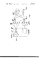
- FIG. 1 is a schematic block diagram of the phased array radar in accordance with the present invention.
- FIG. 2 illustrates an embodiment of a module coupled to a radiating element and employed for the transmission and reception of r.f. signals.
- the radar system of FIG. 1 comprises a phased array antenna of which the radiating elements are designated 1a, 1b, . . . , 1n. These elements are connected to associated modules 2a, 2b, . . . , 2n used for the transmission and reception of r.f. signals. Each of these modules is fed with a transmitter signal and a local oscillator signal and, upon reception of an echo signal by the phased array antenna, each of these modules delivers an i.f. signal.
- the radar thereto contains a signal source/signal processing unit 3 and a transmission system 4 between the signal source/signal processing unit and the individual modules.
- the transmission system 4 comprises conductors for the r.f. transmitter and local oscillator signals and the i.f.
- the transmission system 4 is built up of fiber optical waveguides, hereinafter called optical fibers.
- optical fibers The application of the optical fibers in the transmission system may be realized in different ways, viz.:
- the same optical fiber conveying the transmitter and local oscillator signals to the module concerned.
- the same optical fiber conveying the local oscillator signal to the module concerned.
- transmitter and local oscillator signals and, as the case may be, i.f. signals via optical fibers occurs by modulating these signals on carriers generated by a light source and matched to the optical fibers.
- the transmitter and local oscillator signals are fed to each of the modules via one optical fiber. Since it is not necessary that these two signals be transferred to the modules simultaneously, the transmitter signal (transmitter pulses) and the local oscillator signal are modulated on one and the same carrier, the local oscillator signal in the time intervals between the successive transmitter pulses. If however the i.f. signal is passed through the optical fiber which carries also the transmitter signal and/or the local oscillator signal, as in the cases of 1c, 2c and 2d above, this i.f. signal is modulated on a separate carrier.
- FIG. 2 shows an embodiment of a module matched to a transmission system falling under the above case 1b.
- the module itself is denoted by 2i and the radiating element connected thereto by 1i.
- a 725 MHz transmitter signal and a 750 MHz local oscillator signal are fed, via the optical fiber 5, to a demodulator 6 forming part of the module 2i.
- the transmitter and local oscillator signals modulated on the same optical frequency are demodulated therein by means of a photo-diode circuit, then amplified in amplifier 7 and fed to diplexer 8.
- diplexer 8 the transmitter signals, i.e. the transmitter pulses, are separated from the local oscillator signal present in the time intervals between the successive transmitter pulses.
- the transmitter pulses are subsequently fed to unit 9, where the frequency of the transmitter signals is quadrupled, thus raised to 2900 MHz, then passed through the phase shifter 10, the S-band power amplifier 11, the circulator 12 and finally emitted by the radiating element 1i.
- the local oscillator signal is applied to unit 13, where the frequency of this signal is multiplied in the same way as the transmitter signal in unit 9, thus raised to 3000 MHz, and then supplied to the mixer 15 via phase shifter 14.
- the echo signals received by radiating element 1i are passed, via circulator 12 and amplifier 16, to mixer 15 as well, where their frequency is reduced to the intermediate frequency of 100 MHz.
- the signals so obtained are fed, via i.f.
- phase control occurs in units 10 and 14 after quadruplication of the transmitter and local oscillator frequency. After this process the phase of the signals concerned lend themselves better for adjustment than if this were to be performed before the frequency multiplication. In the latter case the phase control would have to be realized through adjustment of so called lumped elements; in the case in question, this would have to be done with an accuracy four times as great, owing to the frequency multiplication after the phase control.
- the phase control of the signals emitted by the individual radiating elements, as well as that of the local oscillator signals concerned, is done with a computer as is customary with phased-array antennas.
- a light source should be available on the transmitter side of the optical fibers.
- a laser because of the high energy concentration of the light beam emitted, although light emitting diodes (LED's) can be used for certain applications.
- LED's light emitting diodes
- the carriers could be generated by a single gas laser, of which the light beam emitted is distributed over all or a limited number of optical fibers which are in turn split into a greater number of optical fibers.
- Such lasers are however expensive and possess a relatively short lifetime.
- unit 21 consisting of optical components the light beam emitted is divided over a number of optical fibers coupled to the various modules.
- 160 laser diodes say, and dividing the light beam emitted by each of these diodes over 25 optical fibers, a transmission system is obtained for a phased array antenna containing 4000 modules.
- the transmitter signal and the local oscillator signal are modulated on the beam emitted by the light source concerned.
- the signal source/signal processing unit 3 is thereto provided with a transmitter pulse generator 22, a local oscillator 23, a switching element 24 to pass through the local oscillator signal only in the time intervals between the transmitter pulses, and with a laser drive unit 25. From the modulated signal produced by the transmitter and local oscillator signals and applied to drive unit 25 a control signal is obtained to control the current flow through the laser diodes.
- the phase of this control signal is to be the same for all laser diodes; in principle the path length between laser drive unit 25 and laser diodes 20a-d should therefore be equal.
- the laser diodes are controlled by a control signal modulated by the transmitter and local oscillator signals. It is however also possible to modulate the optical signals conducted by the optical fibers.
- FIG. 1 illustrates four of such photodiode circuits 26a-d; in this figure the optical fibers from modules 2a-n come together at unit 27 where the signals transferred via these optical fibers are converged to form an optical beam.
- the signals from the photodiode circuits 26a-d are ultimately combined and fed to the detection/video processing device 28.
- the above-mentioned article in "IEEE Transactions on Communications" describes a feasible embodiment of the photodiode circuits.
- amplitude taper may be introduced in the various modules by electronic means or by providing these modules with optical attenuators having certain attenuation coefficients. Preference is given to the latter method, because an electronic attenuation in the modules will be at the sacrifice of their uniformity, which is of great significance from a manufacturing point of view.
Landscapes
- Engineering & Computer Science (AREA)
- Physics & Mathematics (AREA)
- Computer Networks & Wireless Communication (AREA)
- Electromagnetism (AREA)
- Signal Processing (AREA)
- General Physics & Mathematics (AREA)
- Radar, Positioning & Navigation (AREA)
- Remote Sensing (AREA)
- Variable-Direction Aerials And Aerial Arrays (AREA)
- Radar Systems Or Details Thereof (AREA)
Applications Claiming Priority (2)
| Application Number | Priority Date | Filing Date | Title |
|---|---|---|---|
| NL7807170 | 1978-06-30 | ||
| NL7807170A NL7807170A (nl) | 1978-06-30 | 1978-06-30 | Radarsysteem. |
Publications (1)
| Publication Number | Publication Date |
|---|---|
| US4258363A true US4258363A (en) | 1981-03-24 |
Family
ID=19831172
Family Applications (1)
| Application Number | Title | Priority Date | Filing Date |
|---|---|---|---|
| US06/054,533 Expired - Lifetime US4258363A (en) | 1978-06-30 | 1979-07-03 | Phased array radar |
Country Status (7)
| Country | Link |
|---|---|
| US (1) | US4258363A (de) |
| EP (1) | EP0006650A3 (de) |
| JP (1) | JPS558197A (de) |
| AU (1) | AU4836979A (de) |
| CA (1) | CA1129052A (de) |
| NL (1) | NL7807170A (de) |
| NO (1) | NO792063L (de) |
Cited By (27)
| Publication number | Priority date | Publication date | Assignee | Title |
|---|---|---|---|---|
| FR2548467A1 (fr) * | 1983-06-16 | 1985-01-04 | Int Standard Electric Corp | Radar a antenne reseau commandee en phase a reglage optique |
| US4671604A (en) * | 1985-02-06 | 1987-06-09 | The United States Of America As Represented By The Secretary Of The Air Force | Wavelength dependent, tunable, optical time delay system for electrical signals |
| US4671605A (en) * | 1985-02-06 | 1987-06-09 | The United States Of America As Represented By The Secretary Of The Air Force | Length dependent, optical time delay/filter device for electrical signals |
| US4714314A (en) * | 1985-02-06 | 1987-12-22 | The United States Of America As Represented By The Secretary Of The Air Force | Mode dependent, optical time delay system for electrical signals |
| US4724441A (en) * | 1986-05-23 | 1988-02-09 | Ball Corporation | Transmit/receive module for phased array antenna system |
| US4725844A (en) * | 1985-06-27 | 1988-02-16 | Trw Inc. | Fiber optical discrete phase modulation system |
| US4739334A (en) * | 1986-09-30 | 1988-04-19 | The United States Of America As Represented By The Secretary Of The Air Force | Electro-optical beamforming network for phased array antennas |
| US4814773A (en) * | 1983-05-11 | 1989-03-21 | Hughes Aircraft Company | Fiber optic feed network for radar |
| US4864312A (en) * | 1987-04-14 | 1989-09-05 | Thomson-Csf | Device for optical control of a beam-scanning antenna |
| US4885589A (en) * | 1988-09-14 | 1989-12-05 | General Electric Company | Optical distribution of transmitter signals and antenna returns in a phased array radar system |
| US5029306A (en) * | 1989-08-10 | 1991-07-02 | The Boeing Company | Optically fed module for phased-array antennas |
| US5061937A (en) * | 1989-01-20 | 1991-10-29 | Kabushiki Kaisha Toshiba | Array antenna apparatus |
| US5164735A (en) * | 1991-11-06 | 1992-11-17 | Grumman Aerospace Corporation | Optical implementation of a space fed antenna |
| EP0504589A3 (en) * | 1991-03-20 | 1993-03-24 | Dornier Gmbh | Method for controlling an active antenna |
| US5374935A (en) * | 1993-02-23 | 1994-12-20 | University Of Southern California | Coherent optically controlled phased array antenna system |
| EP0623969A3 (de) * | 1993-05-03 | 1995-12-27 | Deutsche Aerospace | Gruppenantenne mit optischem Strahlformungs-Netzwerk. |
| US5721556A (en) * | 1996-11-08 | 1998-02-24 | Northrop Grumman Corporation | Fiberoptic manifold and time delay arrangement for a phased array antenna |
| US20050156778A1 (en) * | 2004-01-15 | 2005-07-21 | Hrl Laboratories, Llc. | RF lightwave coding system for radar pulse compression |
| WO2005119842A1 (fr) * | 2004-06-03 | 2005-12-15 | Thales | Dispositif de formation de faisceaux a la reception pour une antenne a elements rayonnants |
| RU2298810C1 (ru) * | 2005-10-04 | 2007-05-10 | Дмитрий Феоктистович Зайцев | Приемно-передающий оптоэлектронный модуль афар |
| US20070166053A1 (en) * | 2004-07-14 | 2007-07-19 | Ngk Insulators, Ltd. | Radio oscillating and radar systems |
| CN100392426C (zh) * | 2005-10-20 | 2008-06-04 | 武汉大学 | 单通道相控阵接收信号重构及处理方法 |
| US20090051582A1 (en) * | 2007-02-07 | 2009-02-26 | Lockheed Martin Corporation | Miniaturized microwave-photonic receiver |
| US20100221015A1 (en) * | 2006-02-28 | 2010-09-02 | Lockheed Martin Corporation | Method and system for signal processing by modulation of an optical signal with a multichannel radio frequency signal |
| US7898464B1 (en) * | 2006-04-11 | 2011-03-01 | Lockheed Martin Corporation | System and method for transmitting signals via photonic excitation of a transmitter array |
| US20150180122A1 (en) * | 2013-12-24 | 2015-06-25 | The Boeing Company | Integral rf-optical phased array module |
| US10324166B2 (en) * | 2015-09-28 | 2019-06-18 | Rockwell Collins, Inc. | Affordable combined pulsed/FMCW radar AESA |
Families Citing this family (13)
| Publication number | Priority date | Publication date | Assignee | Title |
|---|---|---|---|---|
| JPS597277A (ja) * | 1982-07-06 | 1984-01-14 | Mitsubishi Electric Corp | フエ−ズド・アレイ・レ−ダ |
| CA1238713A (en) * | 1984-06-04 | 1988-06-28 | Alliedsignal Inc. | Antenna feed network |
| SE456536B (sv) * | 1985-03-08 | 1988-10-10 | Ericsson Telefon Ab L M | Testanordning i ett radarsystem med en elektriskt syyrd antenn |
| US4736463A (en) * | 1986-08-22 | 1988-04-05 | Itt Corporation | Electro-optically controlled wideband multi-beam phased array antenna |
| US4832433A (en) * | 1986-12-31 | 1989-05-23 | Hughes Aircraft Company | Fiber-optic feed network using series/parallel connected light emitting opto-electronic components |
| JP2558112B2 (ja) * | 1987-02-06 | 1996-11-27 | 三菱電機株式会社 | アンテナ装置 |
| JPH0758860B2 (ja) * | 1987-02-06 | 1995-06-21 | 三菱電機株式会社 | アンテナ装置 |
| JPH0755279B2 (ja) * | 1987-02-13 | 1995-06-14 | 株式会社日立製作所 | 洗濯機 |
| JPS63267003A (ja) * | 1987-04-24 | 1988-11-04 | Mitsubishi Electric Corp | アンテナ装置 |
| FR2614471B1 (fr) * | 1987-04-27 | 1989-10-20 | Comp Generale Electricite | Systeme d'antenne adaptatif pour ondes radioelectriques, notamment d'hyperfrequences |
| AU633270B2 (en) * | 1988-09-13 | 1993-01-28 | Nec Corporation | Array antenna device having ic units with if conversion circuits for coupling antenna elements and signal combiner |
| EP0441180B1 (de) * | 1989-01-09 | 1999-07-07 | Mitsubishi Denki Kabushiki Kaisha | Mikrowellenschaltungselemente enthaltende integrierte Schaltungsanordnung |
| CN103257628B (zh) * | 2013-02-07 | 2016-01-27 | 王�琦 | 一种雷达远程操控的方法和装置 |
Citations (1)
| Publication number | Priority date | Publication date | Assignee | Title |
|---|---|---|---|---|
| US4028702A (en) * | 1975-07-21 | 1977-06-07 | International Telephone And Telegraph Corporation | Fiber optic phased array antenna system for RF transmission |
Family Cites Families (3)
| Publication number | Priority date | Publication date | Assignee | Title |
|---|---|---|---|---|
| US3878520A (en) * | 1973-01-24 | 1975-04-15 | Stanford Research Inst | Optically operated microwave phased-array antenna system |
| DE2354668C2 (de) * | 1973-11-02 | 1982-06-24 | Maximilian Dr. 2430 Sierksdorf Wächtler | Peilantennensystem mit räumlich verteilten Einzelantennen |
| US4128759A (en) * | 1977-11-21 | 1978-12-05 | The United States Of America As Represented By The Secretary Of The Navy | Fiber optic delay line filter |
-
1978
- 1978-06-30 NL NL7807170A patent/NL7807170A/nl not_active Application Discontinuation
-
1979
- 1979-06-08 EP EP79200289A patent/EP0006650A3/de not_active Withdrawn
- 1979-06-20 NO NO792063A patent/NO792063L/no unknown
- 1979-06-25 AU AU48369/79A patent/AU4836979A/en not_active Abandoned
- 1979-06-25 CA CA330,478A patent/CA1129052A/en not_active Expired
- 1979-06-29 JP JP8153679A patent/JPS558197A/ja active Pending
- 1979-07-03 US US06/054,533 patent/US4258363A/en not_active Expired - Lifetime
Patent Citations (1)
| Publication number | Priority date | Publication date | Assignee | Title |
|---|---|---|---|---|
| US4028702A (en) * | 1975-07-21 | 1977-06-07 | International Telephone And Telegraph Corporation | Fiber optic phased array antenna system for RF transmission |
Cited By (35)
| Publication number | Priority date | Publication date | Assignee | Title |
|---|---|---|---|---|
| US4814773A (en) * | 1983-05-11 | 1989-03-21 | Hughes Aircraft Company | Fiber optic feed network for radar |
| FR2548467A1 (fr) * | 1983-06-16 | 1985-01-04 | Int Standard Electric Corp | Radar a antenne reseau commandee en phase a reglage optique |
| US4620193A (en) * | 1983-06-16 | 1986-10-28 | International Standard Electric Corporation | Optical phase array radar |
| US4714314A (en) * | 1985-02-06 | 1987-12-22 | The United States Of America As Represented By The Secretary Of The Air Force | Mode dependent, optical time delay system for electrical signals |
| US4671605A (en) * | 1985-02-06 | 1987-06-09 | The United States Of America As Represented By The Secretary Of The Air Force | Length dependent, optical time delay/filter device for electrical signals |
| US4671604A (en) * | 1985-02-06 | 1987-06-09 | The United States Of America As Represented By The Secretary Of The Air Force | Wavelength dependent, tunable, optical time delay system for electrical signals |
| US4725844A (en) * | 1985-06-27 | 1988-02-16 | Trw Inc. | Fiber optical discrete phase modulation system |
| US4724441A (en) * | 1986-05-23 | 1988-02-09 | Ball Corporation | Transmit/receive module for phased array antenna system |
| US4739334A (en) * | 1986-09-30 | 1988-04-19 | The United States Of America As Represented By The Secretary Of The Air Force | Electro-optical beamforming network for phased array antennas |
| US4864312A (en) * | 1987-04-14 | 1989-09-05 | Thomson-Csf | Device for optical control of a beam-scanning antenna |
| US4885589A (en) * | 1988-09-14 | 1989-12-05 | General Electric Company | Optical distribution of transmitter signals and antenna returns in a phased array radar system |
| US5061937A (en) * | 1989-01-20 | 1991-10-29 | Kabushiki Kaisha Toshiba | Array antenna apparatus |
| US5029306A (en) * | 1989-08-10 | 1991-07-02 | The Boeing Company | Optically fed module for phased-array antennas |
| EP0504589A3 (en) * | 1991-03-20 | 1993-03-24 | Dornier Gmbh | Method for controlling an active antenna |
| US5367305A (en) * | 1991-03-20 | 1994-11-22 | Dornier Gmbh | Method and apparatus for controlling an active antenna |
| US5164735A (en) * | 1991-11-06 | 1992-11-17 | Grumman Aerospace Corporation | Optical implementation of a space fed antenna |
| US5374935A (en) * | 1993-02-23 | 1994-12-20 | University Of Southern California | Coherent optically controlled phased array antenna system |
| DE4314406C2 (de) * | 1993-05-03 | 2002-11-21 | Eads Deutschland Gmbh | Gruppenantenne mit optischem Strahlformungs-Netzwerk |
| EP0623969A3 (de) * | 1993-05-03 | 1995-12-27 | Deutsche Aerospace | Gruppenantenne mit optischem Strahlformungs-Netzwerk. |
| US5721556A (en) * | 1996-11-08 | 1998-02-24 | Northrop Grumman Corporation | Fiberoptic manifold and time delay arrangement for a phased array antenna |
| US20050156778A1 (en) * | 2004-01-15 | 2005-07-21 | Hrl Laboratories, Llc. | RF lightwave coding system for radar pulse compression |
| US7053814B2 (en) * | 2004-01-15 | 2006-05-30 | Hrl Laboratories, Llc | RF lightwave coding system for radar pulse compression |
| WO2005119842A1 (fr) * | 2004-06-03 | 2005-12-15 | Thales | Dispositif de formation de faisceaux a la reception pour une antenne a elements rayonnants |
| US7446696B2 (en) * | 2004-07-14 | 2008-11-04 | Ngk Insulators, Ltd. | Radio oscillating and radar systems |
| US20070166053A1 (en) * | 2004-07-14 | 2007-07-19 | Ngk Insulators, Ltd. | Radio oscillating and radar systems |
| RU2298810C1 (ru) * | 2005-10-04 | 2007-05-10 | Дмитрий Феоктистович Зайцев | Приемно-передающий оптоэлектронный модуль афар |
| CN100392426C (zh) * | 2005-10-20 | 2008-06-04 | 武汉大学 | 单通道相控阵接收信号重构及处理方法 |
| US20100221015A1 (en) * | 2006-02-28 | 2010-09-02 | Lockheed Martin Corporation | Method and system for signal processing by modulation of an optical signal with a multichannel radio frequency signal |
| US7801447B1 (en) | 2006-02-28 | 2010-09-21 | Lockheed Martin Corporation | Method and system for signal processing by modulation of an optical signal with a multichannel radio frequency signal |
| US7898464B1 (en) * | 2006-04-11 | 2011-03-01 | Lockheed Martin Corporation | System and method for transmitting signals via photonic excitation of a transmitter array |
| US20090051582A1 (en) * | 2007-02-07 | 2009-02-26 | Lockheed Martin Corporation | Miniaturized microwave-photonic receiver |
| US7724179B2 (en) * | 2007-02-07 | 2010-05-25 | Lockheed Martin Corporation | Miniaturized microwave-photonic receiver |
| US20150180122A1 (en) * | 2013-12-24 | 2015-06-25 | The Boeing Company | Integral rf-optical phased array module |
| US9595757B2 (en) * | 2013-12-24 | 2017-03-14 | The Boeing Company | Integral RF-optical phased array module |
| US10324166B2 (en) * | 2015-09-28 | 2019-06-18 | Rockwell Collins, Inc. | Affordable combined pulsed/FMCW radar AESA |
Also Published As
| Publication number | Publication date |
|---|---|
| JPS558197A (en) | 1980-01-21 |
| AU4836979A (en) | 1980-01-03 |
| NL7807170A (nl) | 1980-01-03 |
| CA1129052A (en) | 1982-08-03 |
| EP0006650A3 (de) | 1980-01-23 |
| NO792063L (no) | 1980-01-03 |
| EP0006650A2 (de) | 1980-01-09 |
Similar Documents
| Publication | Publication Date | Title |
|---|---|---|
| EP0006650A2 (de) | Radarsystem | |
| US4814773A (en) | Fiber optic feed network for radar | |
| US5369410A (en) | Opto-electrical transmitter/receiver module | |
| EP0471226B1 (de) | Phasengesteuerte Gruppe mit breitbandiger optoelektronischer, photonischer Antennenstrahlsteuerung | |
| EP0408676B1 (de) | Optischer strahlformer für eine hochfrequenz-gruppenantenne | |
| US5999128A (en) | Multibeam phased array antennas and methods | |
| US5029306A (en) | Optically fed module for phased-array antennas | |
| KR880003451A (ko) | 전자 광학 제어식 광대역 다중비임 페이스드 어레이 안테나 | |
| US11283168B2 (en) | Device for optically receiving a signal coming from a phased antenna array and associated antenna system | |
| US4595926A (en) | Dual space fed parallel plate lens antenna beamforming system | |
| US4832433A (en) | Fiber-optic feed network using series/parallel connected light emitting opto-electronic components | |
| US4864310A (en) | Adaptive antenna system for radio waves, in particular for microwaves | |
| US4583096A (en) | Fiber optic data distribution for phased array antenna | |
| US5025487A (en) | System for transmitting information on interferometrically generated optical carriers | |
| Bhasin et al. | Optical techniques to feed and control GaAs MMIC modules for phased array antenna applications | |
| US5721556A (en) | Fiberoptic manifold and time delay arrangement for a phased array antenna | |
| US3406399A (en) | Multibeam formation means for array radar | |
| Paul | Optical beam forming and steering for phased-array antenna | |
| EP0623969B1 (de) | Gruppenantenne mit optischem Strahlformungs-Netzwerk | |
| US3444559A (en) | Phased array multibeam formation antenna system | |
| GB2324911A (en) | Antenna array | |
| RU2725758C1 (ru) | Широкодиапазонный интеллектуальный бортовой комплекс связи с применением радиофотонных элементов | |
| Herczfeld | The Application of Lightwave Technology to Microwaves | |
| Horikawa et al. | Self-heterodyning optical beam forming network for multibeam active phased array antenna | |
| Yen et al. | EHF fiber optic-based antenna array |