US4275508A - Clothes dryer temperature control system - Google Patents
Clothes dryer temperature control system Download PDFInfo
- Publication number
- US4275508A US4275508A US06/110,580 US11058080A US4275508A US 4275508 A US4275508 A US 4275508A US 11058080 A US11058080 A US 11058080A US 4275508 A US4275508 A US 4275508A
- Authority
- US
- United States
- Prior art keywords
- temperature
- sensor
- schedule
- cooling
- heating
- Prior art date
- Legal status (The legal status is an assumption and is not a legal conclusion. Google has not performed a legal analysis and makes no representation as to the accuracy of the status listed.)
- Expired - Lifetime
Links
- 238000001816 cooling Methods 0.000 claims abstract description 48
- 238000010438 heat treatment Methods 0.000 claims abstract description 45
- 238000001035 drying Methods 0.000 claims description 21
- 230000007423 decrease Effects 0.000 claims description 7
- 230000004044 response Effects 0.000 claims description 7
- 238000001704 evaporation Methods 0.000 claims description 2
- 239000012530 fluid Substances 0.000 claims 2
- 230000008020 evaporation Effects 0.000 claims 1
- 238000002955 isolation Methods 0.000 claims 1
- 230000000007 visual effect Effects 0.000 abstract description 2
- 238000000034 method Methods 0.000 description 10
- 238000004804 winding Methods 0.000 description 8
- 239000003990 capacitor Substances 0.000 description 7
- 238000010586 diagram Methods 0.000 description 6
- 239000007787 solid Substances 0.000 description 5
- 230000008859 change Effects 0.000 description 4
- 239000004065 semiconductor Substances 0.000 description 4
- 239000004744 fabric Substances 0.000 description 3
- 230000000903 blocking effect Effects 0.000 description 2
- 230000000694 effects Effects 0.000 description 2
- 230000001939 inductive effect Effects 0.000 description 2
- 230000007704 transition Effects 0.000 description 2
- 238000012935 Averaging Methods 0.000 description 1
- 239000000919 ceramic Substances 0.000 description 1
- 230000003247 decreasing effect Effects 0.000 description 1
- 238000001514 detection method Methods 0.000 description 1
- 238000001914 filtration Methods 0.000 description 1
- 230000004048 modification Effects 0.000 description 1
- 238000012986 modification Methods 0.000 description 1
- 238000005476 soldering Methods 0.000 description 1
- 239000012209 synthetic fiber Substances 0.000 description 1
- 229920002994 synthetic fiber Polymers 0.000 description 1
- 230000001052 transient effect Effects 0.000 description 1
- XLYOFNOQVPJJNP-UHFFFAOYSA-N water Substances O XLYOFNOQVPJJNP-UHFFFAOYSA-N 0.000 description 1
- 238000003466 welding Methods 0.000 description 1
- 230000037303 wrinkles Effects 0.000 description 1
Images


Classifications
-
- G—PHYSICS
- G05—CONTROLLING; REGULATING
- G05D—SYSTEMS FOR CONTROLLING OR REGULATING NON-ELECTRIC VARIABLES
- G05D23/00—Control of temperature
- G05D23/19—Control of temperature characterised by the use of electric means
- G05D23/1902—Control of temperature characterised by the use of electric means characterised by the use of a variable reference value
- G05D23/1904—Control of temperature characterised by the use of electric means characterised by the use of a variable reference value variable in time
-
- D—TEXTILES; PAPER
- D06—TREATMENT OF TEXTILES OR THE LIKE; LAUNDERING; FLEXIBLE MATERIALS NOT OTHERWISE PROVIDED FOR
- D06F—LAUNDERING, DRYING, IRONING, PRESSING OR FOLDING TEXTILE ARTICLES
- D06F58/00—Domestic laundry dryers
- D06F58/32—Control of operations performed in domestic laundry dryers
- D06F58/34—Control of operations performed in domestic laundry dryers characterised by the purpose or target of the control
- D06F58/36—Control of operational steps, e.g. for optimisation or improvement of operational steps depending on the condition of the laundry
- D06F58/38—Control of operational steps, e.g. for optimisation or improvement of operational steps depending on the condition of the laundry of drying, e.g. to achieve the target humidity
-
- D—TEXTILES; PAPER
- D06—TREATMENT OF TEXTILES OR THE LIKE; LAUNDERING; FLEXIBLE MATERIALS NOT OTHERWISE PROVIDED FOR
- D06F—LAUNDERING, DRYING, IRONING, PRESSING OR FOLDING TEXTILE ARTICLES
- D06F2101/00—User input for the control of domestic laundry washing machines, washer-dryers or laundry dryers
- D06F2101/02—Characteristics of laundry or load
-
- D—TEXTILES; PAPER
- D06—TREATMENT OF TEXTILES OR THE LIKE; LAUNDERING; FLEXIBLE MATERIALS NOT OTHERWISE PROVIDED FOR
- D06F—LAUNDERING, DRYING, IRONING, PRESSING OR FOLDING TEXTILE ARTICLES
- D06F2103/00—Parameters monitored or detected for the control of domestic laundry washing machines, washer-dryers or laundry dryers
- D06F2103/02—Characteristics of laundry or load
- D06F2103/08—Humidity
-
- D—TEXTILES; PAPER
- D06—TREATMENT OF TEXTILES OR THE LIKE; LAUNDERING; FLEXIBLE MATERIALS NOT OTHERWISE PROVIDED FOR
- D06F—LAUNDERING, DRYING, IRONING, PRESSING OR FOLDING TEXTILE ARTICLES
- D06F2103/00—Parameters monitored or detected for the control of domestic laundry washing machines, washer-dryers or laundry dryers
- D06F2103/28—Air properties
- D06F2103/32—Temperature
-
- D—TEXTILES; PAPER
- D06—TREATMENT OF TEXTILES OR THE LIKE; LAUNDERING; FLEXIBLE MATERIALS NOT OTHERWISE PROVIDED FOR
- D06F—LAUNDERING, DRYING, IRONING, PRESSING OR FOLDING TEXTILE ARTICLES
- D06F2103/00—Parameters monitored or detected for the control of domestic laundry washing machines, washer-dryers or laundry dryers
- D06F2103/38—Time, e.g. duration
-
- D—TEXTILES; PAPER
- D06—TREATMENT OF TEXTILES OR THE LIKE; LAUNDERING; FLEXIBLE MATERIALS NOT OTHERWISE PROVIDED FOR
- D06F—LAUNDERING, DRYING, IRONING, PRESSING OR FOLDING TEXTILE ARTICLES
- D06F2105/00—Systems or parameters controlled or affected by the control systems of washing machines, washer-dryers or laundry dryers
- D06F2105/28—Electric heating
-
- D—TEXTILES; PAPER
- D06—TREATMENT OF TEXTILES OR THE LIKE; LAUNDERING; FLEXIBLE MATERIALS NOT OTHERWISE PROVIDED FOR
- D06F—LAUNDERING, DRYING, IRONING, PRESSING OR FOLDING TEXTILE ARTICLES
- D06F2105/00—Systems or parameters controlled or affected by the control systems of washing machines, washer-dryers or laundry dryers
- D06F2105/58—Indications or alarms to the control system or to the user
- D06F2105/60—Audible signals
-
- D—TEXTILES; PAPER
- D06—TREATMENT OF TEXTILES OR THE LIKE; LAUNDERING; FLEXIBLE MATERIALS NOT OTHERWISE PROVIDED FOR
- D06F—LAUNDERING, DRYING, IRONING, PRESSING OR FOLDING TEXTILE ARTICLES
- D06F2105/00—Systems or parameters controlled or affected by the control systems of washing machines, washer-dryers or laundry dryers
- D06F2105/62—Stopping or disabling machine operation
Definitions
- This invention relates to a control system for a clothes dryer, which specifically provides a drying program based upon the air temperature and not upon a timed operation.
- control techniques for clothes dryers have utilized time drying periods during which moisture is removed from the clothes to be dried by passing heated air over the clothes for a fixed period of time. This resulted in a drying period which may have been longer or shorter than was needed to properly dry the clothes.
- Another clothes drying technique which has been used in that of controlling the drying period according to a direct or indirect method of determining the moisture content of the clothes.
- a resistance sensor is utilized to monitor the resistance of the clothes as they are dried. As moisture is removed from the clothes, the sensed resistance increases, and the heating cycle of the drying period is terminated upon detection of a predetermined resistance.
- the principle employed in such a method is that the sensed resistance will indicate the percent dryness of the clothes.
- exhaust air temperature is sensed to determine percent dryness.
- air temperature remains relatively constant while heat input goes into changing the phase of water, i.e., evaporating it from the clothes.
- the indirect method operates on the principle that once the moisture is driven off, heat input goes into raising the temperature of the drying air.
- the temperature increase is detected by a bimetal thermostat which operates at a fixed predetermined temperature.
- a cooling cycle comprising a predetermined timed portion of the drying period has been utilized to lower the temperature of the clothes.
- Such a timed cooling cycle has the same disadvantages of a timed heating cycle in that the clothes may not be sufficiently cooled (thereby resulting in an uncomfortable or unsafe condition when clothes are to be removed from the dryer); or, if the timed cooling cycle is in excess of that required to cool the clothes to the proper temperature, unwanted wrinkles may be set in the fabric (especially with fabrics made from certain synthetic fibers).
- the present invention overcomes the above described shortcomings of timed cooling cycle clothes dryer control systems by providing a cooling cycle control system for a clothes dryer comprising a temperature sensor which provides a signal indicative of drying air temperature and a heater which is selectively actuated to heat the drying air.
- a selector is provided which is operable to provide a predetermined cooling schedule and includes an output indicative of the schedule selected.
- a control which receives the output from the selector is operative upon deactuation of the heater to cool the drying air according to the selected cooling schedule until a predetermined final temperature is detected by the temperature sensor.
- the drying program comprises a predetermined heating cycle and a predetermined cooling cycle.
- the heater is selectively actuated to heat the drying air until a desired heating temperature is obtained, whereupon the heater is deactuated.
- the cooling cycle is then initiated and continued until a desired final temperature as determined by the temperature sensor is reached.
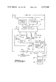
- FIG. 1 is a wiring diagram for the control system of the present invention.
- FIG. 2 is a block diagram of the control system of the present invention showing important subsystems and interconnections;
- FIG. 3 is a drawing key for FIGS. 4A and 4B;
- FIGS. 4A and 4B collectively comprise a detailed electrical schematic of the control system of the present invention
- FIG. 5 is a top view of the temperature sensor in its enclosure as utilized in the present invention.
- FIG. 6 is a section view taken along section indicating line 6--6 of FIG. 5.
- resistance values are given in ohms
- capacitance values are given in microfarads, denoted "mf”
- diodes are type 1N4001. Circuit common is indicated by an inverted triangle 108 in the block diagram of FIG. 2 and the electrical schematics of FIGS. 4A and 4B.
- the control system includes a selector, or set of program input switches 12, a solic state control circuit 14, a set of visual indicators or program display 16, a heater relay 18, a motor relay 20, and an alarm 22.
- a sensor 24 senses drying air temperature and provides a temperature signal to the solid state control circuit 14.
- control system 10 Preferably, power is supplied to control system 10 from a nominal 120 volts AC, 60 Hz power source shown generally at 26, that is, such electrical power is applied between leads 28 and 30. Electrical power is applied to solid state control circuit 14 by closure of an on-off switch 32. Electrical power at a nominal 240 volts AC, 60 Hz is provided between leads 30 and 34 to power heater 36 when selectively actuated by heater relay contacts 38. A blower 39 will move air over heater 36 and the clothes to be dried in a clothes drum 41. A motor 40 drives blower 39 and clothes drum 41 through a drive belt and pulley arrangement represented by dashed lines 43a, 43b and 43c.
- a heater overtemperature switch 42 preferably of the known bimetal type detects an unsafe temperature and removes electrical power from heater 36.
- Motor 40 is comprised of a start winding 44, a run winding 46, a thermal overload interruptor 48, a first centrifugal switch 50, and a second centrifugal switch 52.
- the motor wiring connections are completed through a set of motor relay contacts 54, a momentary contact push button start switch 56, and a door-open cut-out switch 58.
- on-off switch 32 is closed, power solid state control circuit 14.
- a predetermined drying program as for example "woolen”, “regular”, “permanent press”, “delicate” is selected from program input switches 12 and is indicated by program display 16.
- Door switch 58 is closed by closing a dryer door (not shown), and start switch 56 is momentarily closed causing motor 14 to begin rotation under operation of start winding 44.
- centrifugal switch 50 transfers to a running position, disconnecting start winding 44 and powering run winding 46 through normally closed MR (motor relay) contacts 54.
- Centrifugal switch 52 will also close once sufficient rotational speed has been attained, thus providing a closed-circuit path between heater 36 and electrical power lead 30.
- Solid state control circuit 14 will then energize heater relay 18, closing normally open HR (heater relay) contacts 38, powering heater 36 which then heats the air used to dry clothes in the dryer.
- sensor 24 is located in the exhaust air passageway of clothes drum 41 to detect air temperature after it has passed over the clothes in the dryer.
- Heater 36 continues to heat the air until solid state control circuit 14 receives a temperature signal from sensor 24 indicating that a predetermined heating temperature has been reached. At that point in the program circuit 14 deenergizes heater relay 18 opening the circuit to heater 36 at HR contacts 38. Motor 40 continues to run until circuit 14 detects that a desired final temperature has been reached as indicated by the temperature signal from sensor 24. Upon receipt of the final temperature signal from sensor 24 circuit 14 energizes motor relay 20, interrupting power to motor 40 at MR contacts 54, thereby stopping motor 40, sounding alarm 22 for a brief period of time to indicate the drying program is completed, and clearing circuit 14 and program display 16 of the drying program previously selected.
- a DC power supply 60 is used to provide DC power to the remainder of electronic control system 10.
- a power-up reset pulse circuit 62 clears a program memory 64 and resets a heating cycle memory or latch 74 when power is initially applied to the system.
- a timer 66 provides a reset pulse through diode 68 at the completion of the drying program.
- heating cycle comparator 70 and a cooling cycle comparator 72 are manufacturer's type MC1710 integrated circuits obtainable from Motorola, Inc., Semiconductor Group Integrated Circuits Division, 2200 West Broadway M370, Mesa, AZ 85201.
- Latch 74 is one half of an integrated circuit, manufacturer's type CD4027, obtainable from RCA Corporation, 30 Rockefeller Plaza, New York, NY 10020. Latch 74 is designated a J-K Master-Slave Flip-Flop by the manufacturer, however, as used in control system 10, latch 74 is connected to operate as an S-R (set-reset) flip-flop.
- the Q output of latch 74 will apply a logic low (hereinafter “0") to lead 76; and a logic high (hereinafter “1") will be applied to lead 78 from the Q ("Q-not") output of latch 74.
- 0 corresponds to a nominal 0 volts
- 1 corresponds nominally to a DC supply voltage "V c " of +12 volts.
- a predetermined heating schedule output signal associated with a desired heating temperature will be applied to lead 80 by program memory 64, and a predetermined cooling schedule will be available from program memory 64 at lead 82; however latch 74 (while reset) will hold lead 82 at a nominal +0.5 volts through diode 84. Since the voltage on lead 80 is less than that corresponding to a "1", a diode 86 is reverse biased, blocking the "1" on lead 78 from affecting the voltage on lead 80. A diode 88 connects the heating schedule output signal on lead 80 to sensor 24.
- sensor 24 is a manufacturer's type TSP102 thermistor, obtainable from Texas Instruments Corporation, P.O. Box 225474, Dallas, TX 75265.
- Sensor 24 is preferably a positive temperature coefficient thermistor having a nominal 1000 ohms resistance at 25° C. and a linear coefficient of 0.7%/C.°. Sensor 24 is located so as to be sensitive to drying air temperature, and will exhibit a change in resistance linearly proportional to the sensed temperature.
- Sensor 24 will increase in resistance as the temperature of drying air increases, raising the voltage on lead 80 until it equals a reference voltage on lead 90 connected to the inverting input of comparator 70.
- the output of comparator 70 on lead 92 switches from a "0" to a "1".
- Latch 74 is “set” causing lead 76 to go to a "1” and lead 78 to go to a "0".
- Heater 36 is thereby turned off through a heater relay and driver 94; and diode 86 is forward biased holding lead 80 to a nominal +0.5 volts, thus removing the heating schedule output signal from sensor 24.
- Diode 84 is reverse biased, enabling the cooling schedule available on lead 82 from program memory 64 to be applied to sensor 24 through a diode 97.
- the voltage on lead 82 is greater than a reference voltage on lead 96 connected to the inverting input of comparator 72.
- the output of comparator 72 will thereupon switch from a "0" to a 1 on lead 98, thus effecting a crossover from the heating cycle to the cooling cycle of the drying program. Since heater 36 has been deactuated, drying air temperature will decrease causing sensor 24 to decrease in resistance, resulting in a decrease in voltage on lead 82 until the voltage on lead 82 equals the reference voltage on lead 96.
- the signal on lead 98 will switch from a "1" to a "0", causing a negative-going pulse to appear on lead 100, coupled by a 0.05 mf capacitor 102.
- the negative-going pulse on lead 100 will trigger a timer 66.
- any suitable timer may be employed, in the present practice of the invention a manufacturer's type LM555, obtainable from National Semiconductor Corporation, Semiconductor Division, 2900 Semiconductor Drive, Santa Clara, CA 95050 has been found satisfactory.
- Timer 66 operates as a monostable multivibrator which provides a nominal 60 second "1" output pulse on lead 104, sounding alarm 22 for one minute, (indicating the completion of the drying program), and providing a reset pulse through diode 68, and energizing motor relay and driver 106, thus stopping motor 40 (in FIG. 1).
- power-up reset pulse circuit 62 is comprised of a 330K resistor 110, a 0.1 mf capacitor 112, a 10K resistor 114, a 0.1 mf capacitor 116 and two digital logic inverters 118 and 120.
- digital logic inverters 118 and 120 are as contained in a Hex Inverter/Buffer integrated circuit, RCA manufacturer's type CD4049.
- Power-up reset pulse circuit 62 provides a nominal 10 ms "1" pulse on reset lead 122 when power is first applied to resistor 110.
- the reset pulse on lead 122 resets latches 124a through 124d, which latches comprise, in conjunction with associated circuitry, program memory 64.
- DC power supply 60 is comprised of a transformer 132 whose primary winding 134 is preferably connected to the 120 VAC power source 26 through switch 32 (see FIG. 1). It will be understood by those having skill in the art that any suitable power transformer may be used however, in the present practice of the invention a transformer 132 having a 24 VAC center-tapped secondary winding 136, manufacturer's part No. 10526617, obtainable from Transformer Manufacturer's Inc., 7051 W. Wilson Avenue, Chicago, Ill 60656 has been found satisfactory. Transformer secondary winding 136 has a nominal 15 watt capacity. Diodes 138 rectify the secondary voltage from transformer 132, and a 500 mf capacitor 140 provides filtering for the "V c " DC power supply lead 142, which provides a nominally +12 volts to the remaining circuits.
- switches 144a through 144d and associated circuitry comprise program input switches 12 (shown in FIGS. 1 and 2). Momentarily closing switch 144a will set latch 124a and provide a "1" reset pulse on lead 122, resetting latches 74, and 124b through d.
- a "1" is simultaneously applied to both S and R inputs of latch 124a by closing switch 144a, it has been found that in the circuit shown, comprising a 10K resistor 148a and a diode 150a, latch 124a remains “set” after switch 144a is opened.
- each of switches 144b through d will cooperate with the respective combination of one of 10K resistors 148b through d and a corresponding diode 150b through d to "set" the associated latch and reset all other latches.
- latch 124a When latch 124a is set, light-emitting diode or LED 152a is turned on, giving a visible indication that latch 124a is set.
- LED's 152b through d operate in a similar manner for latches 124b through d.
- a 1K resistor 154 provides a path to circuit common and, collectively with LED's 152a through d, comprises program display 16.
- a pair of 44 ohm resistors 160 and 162 and a 2K potentiometer 164 (which is connected as a variable resistor and nominally set for 1135 ohms) collectively comprise a resistor ladder 166 capable of providing a heating schedule to sensor 24.
- Ladder 166 is powered by one of latches 124a through d to provide a voltage divider whose output is on lead 80. As shown, 3 temperature schedules are provided with ladder 166.
- Setting latch 124b provides "V c " voltage at diode 156b resulting in the lowest ratio voltage divider, requiring sensor 24 to undergo the largest resistance change to provide a voltage on lead 80 equal to the reference voltage on lead 90.
- powering ladder 166 through one of diodes 156a, 157c, or 156d results in one of two other ratio voltage dividers.
- 44 ohm resistors 168 and 170, and 2K potentiometer 172 collectively comprise a resistor ladder 174 capable of providing a cooling schedule to sensor 24.
- T e , T f , and T g denote respectively high, intermediate, and low heating schedule temperatures; and T h , T i , and T j denote respectively high, intermediate, and low cooling schedule temperatures.
- switch 144a is closed a combination of T f for the heating schedule and T h for the cooling schedule is programmed or selected to provide, in the embodiment described and shown herein, a "woolen" drying program suitable for woolen fabrics.
- Closing switch 144b selects a general purpose or "regular" drying program which comprises schedule pair T e , T i .
- Closing switch 144c selects a "permanent press" drying program comprised of T f , T i .
- heating cycle comparator 70 accepts the reference voltage on lead 90 from a voltage divider comprising a pair of 2.2K resistors 176 and 178.
- heating cycle memory or latch 74 is in a reset state, with its Q output providing a "1" on lead 78.
- a 10K base resistor 180 turns on heater relay driver transistor 182, which is perferably a type 2N3392.
- Heater relay 18 may be any suitable 12 VDC relay and is energized (closing HR contacts 38) when transistor 182 is switched on.
- a diode 184 protects transistor 182 against inductive transients when relay 18 is deenergized.
- sensor 24 provides sufficient resistance to change the voltage divider ratio of ladder 166 and sensor 24 by an amount which increases the voltage on lead 80 until it equals the reference voltage on lead 90. Comparator 70 will then switch from a "0" to a “1” output, setting latch 74, causing a "1" on lead 76 and a “ “ on lead 78. Heater relay 18 is deenergized, opening HR contacts 38, thereby deactuating heater 36. When diode 86 conducts, lead 80 receives a nominal +0.5 volts, removing the heating schedule from sensor 24 by the blocking action of diode 88. At the same time, diode 84 will become reverse biased, permitting the selected cooling schedule from ladder 174 to be applied to sensor 24 through diode 97.
- diode 84 enables comparator 72 by releasing lead 82 from a nominal +0.5 volts maintained thereon during the heating cycle.
- the output of cooling cycle comparator 72 was a "0", because of the reference voltage on lead 96, provided by a pair of 2.2K resistors 186 and 188.
- the voltage on lead 82 will be greater than the reference voltage on lead 96, causing the output of comparator 72 to go to a "1".
- Heater 36 is then deactuated causing drying air temperature to gradually decrease, thereby causing sensor 24 to decrease in resistance.
- sensor 24 decreases in resistance thereby reducing the voltage divider ratio of ladder 174 and sensor 24.
- the output of comparator 72 switches from a "1" to a "0".
- lead 98 is in series with two digital logic inverters 190 and 192 (RCA manufacturer's type CD4049), shown between leads 98a and 98b, the inverters being omitted in FIG. 2 for simplicity. Inverters 190 and 192 provide a faster “1" to "0" transition than is obtained from comparator 72.
- the "1" to “0" transition on lead 98b is coupled through 0.05 mf capacitor 102 and appears on lead 100 as a negative going pulse at the input to timer 66.
- a 10K pullup resistor 194 holds lead 100 at a “1” in the absence of such a negative going pulse.
- a megohm resistor 196 and a 22 mf capacitor 198 are connected to timer 66 and give a nominal 60 second "1" output pulse on lead 104 in response to the negative going pulse on lead 100.
- the "1" output pulse on lead 104 resets all latches through diode 68 and lead 122, and turns off motor 40 (see FIG. 1) by energizing motor relay 20 through a 10K resistor 200, and a type 2N3392 transistor 202.
- a diode 204 protects transistor 202 against inductive transients.
- motor relay 20 When motor relay 20 is energized, it opens MR contacts 54, removing power from motor 40.
- the "1" pulse on lead 104 also powers an integrated circuit 206, preferably an RCA manufacturer's type CD4049 Hex Inverter/Buffer, connected to operate as a nominal 2 KHz oscillator 207 with a 3.9 megohm resistor 208, a 160K resistor 210, a 0.001 mf capacitor 212, and alarm 22.
- Alarm 22 in the preferred embodiment is a manufacturer's type 105CFB ceramic audio tone transducer, available from Gulton Industries, Inc. Piezo Products Div., 300 State College Blvd., Fullerton, CA 92631. However, it will be understood that other suitable devices may be employed for alarm 22. The particular device described is what provides an audible signal for the duration of the nominal 60 second "1" pulse on lead 104.
- the audible signal from alarm 22 indicates that the clothes in the dryer are at the desired final temperature and should be removed.
- sensor 24 is shown in an enclosure or assembly 214, having a cover 216 and an electrically insulating base 218.
- Sensor or thermistor 24 has its leads 220 and 222 preferably formed to support sensor body 224 in a parallel spaced relationship to inside cover face 226.
- Lead 222 is insulated by an electrically non-conductive sleeve 228.
- Leads 220 and 222 are preferably mechanically and electrically bonded at interfaces 230a and 230b by suitable techniques, as for example soldering or welding to terminals 232 and 234 respectively.
- Terminals 232 and 234 have projections 236 and 238 extending away from base 218 to permit rapid and convenient electrical connection to sensor 24.
- Cover 216 has apertures 240 and 242 to provide means to mechanically mount enclosure 214.
- enclosure 214 is mounted such that outside cover face 244 is exposed to the region whose temperature is to be sensed by sensor 24.
- the spacing of sensor body 224 with respect to inside cover face 226, provides a thermal lag between the temperature at outside cover face 244 and sensor body 224.
- the thermal lag provides an averaging or integrating effect, thus making sensor 24 less sensitive to transient temperature fluctuations than it would be if in direct thermal contact with the region to be sensed.
- an "offset" effect is provided as a given temperature is approached when the response of sensor 24 to an increasing temperature is compared to response of sensor 24 to a decreasing temperature, (assuming the temperature rate of change is faster than the thermal lag).
- Sensor 24 thus operates with an apparent offset during dynamic temperature sensing.
- a spacing of 0.0625 inches (1.589 mm) between sensor body 224 and inside cover face 226 is preferred, although a spacing in the range of 0.05 to 0.10 inches (1.27 to 2.54 mm) is satisfactory.
Landscapes
- Engineering & Computer Science (AREA)
- Physics & Mathematics (AREA)
- General Physics & Mathematics (AREA)
- Automation & Control Theory (AREA)
- Textile Engineering (AREA)
- Control Of Washing Machine And Dryer (AREA)
Priority Applications (2)
| Application Number | Priority Date | Filing Date | Title |
|---|---|---|---|
| US06/110,580 US4275508A (en) | 1980-01-09 | 1980-01-09 | Clothes dryer temperature control system |
| CA000367862A CA1155948A (fr) | 1980-01-09 | 1981-01-05 | Regulateur de temperature pour seche-linge |
Applications Claiming Priority (1)
| Application Number | Priority Date | Filing Date | Title |
|---|---|---|---|
| US06/110,580 US4275508A (en) | 1980-01-09 | 1980-01-09 | Clothes dryer temperature control system |
Publications (1)
| Publication Number | Publication Date |
|---|---|
| US4275508A true US4275508A (en) | 1981-06-30 |
Family
ID=22333796
Family Applications (1)
| Application Number | Title | Priority Date | Filing Date |
|---|---|---|---|
| US06/110,580 Expired - Lifetime US4275508A (en) | 1980-01-09 | 1980-01-09 | Clothes dryer temperature control system |
Country Status (2)
| Country | Link |
|---|---|
| US (1) | US4275508A (fr) |
| CA (1) | CA1155948A (fr) |
Cited By (22)
| Publication number | Priority date | Publication date | Assignee | Title |
|---|---|---|---|---|
| US4372054A (en) * | 1981-02-02 | 1983-02-08 | Emhart Industries, Inc. | Method and means for programming the operation of an apparatus |
| EP0080268A1 (fr) * | 1981-10-28 | 1983-06-01 | T.I. Domestic Appliances Limited | Séchoir à tambour |
| US4483082A (en) * | 1982-04-12 | 1984-11-20 | The Maytag Company | Single relay for motor and heater control |
| US4531307A (en) * | 1983-12-27 | 1985-07-30 | The Maytag Company | Fabric dryer control with cycle interrupt |
| US5140493A (en) * | 1988-10-21 | 1992-08-18 | General Electric Company | Control system, method of operating an article cleaning apparatus and controlled article cleaning apparatus |
| EP0893533A3 (fr) * | 1997-07-26 | 1999-06-02 | General Domestic Appliances Limited | Sèche-linge |
| US6079121A (en) * | 1998-08-03 | 2000-06-27 | Ther-O-Disc, Incorporated | Humidity-modulated dual-setpoint temperature controller |
| US6373032B1 (en) * | 1999-06-10 | 2002-04-16 | Maytag Corporation | Apparatus and method for multiple temperature range control |
| US6739069B2 (en) * | 2001-11-30 | 2004-05-25 | Camco Inc. | Cool down temperature control system for clothes dryer |
| US6792694B2 (en) | 2002-06-13 | 2004-09-21 | Camco Inc. | Control system for an automatic clothes dryer |
| US20040200093A1 (en) * | 2000-05-02 | 2004-10-14 | Wunderlin William Joseph | System and method for controlling a dryer appliance |
| US20060218816A1 (en) * | 2005-04-04 | 2006-10-05 | Maytag Corporation | Dryer heat modulation with solid state motor switch |
| US20070033825A1 (en) * | 2005-04-18 | 2007-02-15 | Beauty-Gear International Limited | Hot air blower with ceramic heating element |
| US20070186438A1 (en) * | 2006-02-14 | 2007-08-16 | Woerdehoff Christopher J | Drying mode for automatic clothes dryer |
| US20080088989A1 (en) * | 2006-10-13 | 2008-04-17 | Emerson Electric Co. | Clothes dryer motor with broken belt switch |
| US20090049707A1 (en) * | 2007-08-22 | 2009-02-26 | Miele & Cie.Kg | Laundry dryer with a holding device |
| US20090249960A1 (en) * | 2007-10-12 | 2009-10-08 | Lassota Zbigniew G | Electrically powered beverage brewer and method of making and inventorying same |
| US20110146101A1 (en) * | 2009-12-18 | 2011-06-23 | Whirlpool Corporation | Method for operating a clothes dryer using load temperature determined by an infrared sensor |
| US8549770B2 (en) | 2009-12-18 | 2013-10-08 | Whirlpool Corporation | Apparatus and method of drying laundry with drying uniformity determination |
| US8661706B2 (en) | 2009-12-18 | 2014-03-04 | Whirlpool Corporation | Method for determining load size in a clothes dryer using an infrared sensor |
| DE102007046066B4 (de) | 2006-10-09 | 2018-07-12 | Lg Electronics Inc. | Trockner und Verfahren zum Steuern desselben |
| US20230243085A1 (en) * | 2016-12-28 | 2023-08-03 | Electrolux Appliances Aktiebolag | Appliance with reliable information of a drying cycle |
Citations (11)
| Publication number | Priority date | Publication date | Assignee | Title |
|---|---|---|---|---|
| US2728836A (en) * | 1951-06-07 | 1955-12-27 | Phillips Petroleum Co | Temperature sensing element |
| US3044968A (en) * | 1958-05-13 | 1962-07-17 | Westinghouse Electric Corp | Positive temperature coefficient thermistor materials |
| US3182507A (en) * | 1960-11-30 | 1965-05-11 | Ilikon Corp | Thermal history gage |
| US3231522A (en) * | 1963-09-26 | 1966-01-25 | American Radiator & Standard | Thermistor |
| US3479631A (en) * | 1965-12-22 | 1969-11-18 | Owens Illinois Inc | Thermistors |
| US3526809A (en) * | 1967-08-28 | 1970-09-01 | Texas Instruments Inc | Overload protection apparatus |
| US3702030A (en) * | 1971-03-29 | 1972-11-07 | Whirlpool Co | Digital dryer control circuit |
| US3707857A (en) * | 1971-09-20 | 1973-01-02 | Whirlpool Co | Multi-purpose sensor assembly for automatic washer |
| US3728660A (en) * | 1969-11-21 | 1973-04-17 | Thermo Couple Prod Co Inc | Temperature responsive resistance element for a temperature sensitive control sensor |
| US3952276A (en) * | 1974-02-21 | 1976-04-20 | Siemens Aktiengesellschaft | Fluid tight NTC high temperature sensor and method of producing same |
| US4132008A (en) * | 1977-06-03 | 1979-01-02 | Whirlpool Corporation | Control circuit for drier |
-
1980
- 1980-01-09 US US06/110,580 patent/US4275508A/en not_active Expired - Lifetime
-
1981
- 1981-01-05 CA CA000367862A patent/CA1155948A/fr not_active Expired
Patent Citations (11)
| Publication number | Priority date | Publication date | Assignee | Title |
|---|---|---|---|---|
| US2728836A (en) * | 1951-06-07 | 1955-12-27 | Phillips Petroleum Co | Temperature sensing element |
| US3044968A (en) * | 1958-05-13 | 1962-07-17 | Westinghouse Electric Corp | Positive temperature coefficient thermistor materials |
| US3182507A (en) * | 1960-11-30 | 1965-05-11 | Ilikon Corp | Thermal history gage |
| US3231522A (en) * | 1963-09-26 | 1966-01-25 | American Radiator & Standard | Thermistor |
| US3479631A (en) * | 1965-12-22 | 1969-11-18 | Owens Illinois Inc | Thermistors |
| US3526809A (en) * | 1967-08-28 | 1970-09-01 | Texas Instruments Inc | Overload protection apparatus |
| US3728660A (en) * | 1969-11-21 | 1973-04-17 | Thermo Couple Prod Co Inc | Temperature responsive resistance element for a temperature sensitive control sensor |
| US3702030A (en) * | 1971-03-29 | 1972-11-07 | Whirlpool Co | Digital dryer control circuit |
| US3707857A (en) * | 1971-09-20 | 1973-01-02 | Whirlpool Co | Multi-purpose sensor assembly for automatic washer |
| US3952276A (en) * | 1974-02-21 | 1976-04-20 | Siemens Aktiengesellschaft | Fluid tight NTC high temperature sensor and method of producing same |
| US4132008A (en) * | 1977-06-03 | 1979-01-02 | Whirlpool Corporation | Control circuit for drier |
Cited By (31)
| Publication number | Priority date | Publication date | Assignee | Title |
|---|---|---|---|---|
| US4372054A (en) * | 1981-02-02 | 1983-02-08 | Emhart Industries, Inc. | Method and means for programming the operation of an apparatus |
| EP0080268A1 (fr) * | 1981-10-28 | 1983-06-01 | T.I. Domestic Appliances Limited | Séchoir à tambour |
| US4483082A (en) * | 1982-04-12 | 1984-11-20 | The Maytag Company | Single relay for motor and heater control |
| US4531307A (en) * | 1983-12-27 | 1985-07-30 | The Maytag Company | Fabric dryer control with cycle interrupt |
| US5140493A (en) * | 1988-10-21 | 1992-08-18 | General Electric Company | Control system, method of operating an article cleaning apparatus and controlled article cleaning apparatus |
| EP0893533A3 (fr) * | 1997-07-26 | 1999-06-02 | General Domestic Appliances Limited | Sèche-linge |
| US6079121A (en) * | 1998-08-03 | 2000-06-27 | Ther-O-Disc, Incorporated | Humidity-modulated dual-setpoint temperature controller |
| US6373032B1 (en) * | 1999-06-10 | 2002-04-16 | Maytag Corporation | Apparatus and method for multiple temperature range control |
| US20040200093A1 (en) * | 2000-05-02 | 2004-10-14 | Wunderlin William Joseph | System and method for controlling a dryer appliance |
| US7013578B2 (en) | 2000-05-02 | 2006-03-21 | General Electric Company | System and method for controlling a dryer appliance |
| US20060191161A1 (en) * | 2000-05-02 | 2006-08-31 | Wunderlin William J | System and method for controlling a dryer appliance |
| US7478486B2 (en) | 2000-05-02 | 2009-01-20 | General Electric Company | System and method for controlling a dryer appliance |
| US6739069B2 (en) * | 2001-11-30 | 2004-05-25 | Camco Inc. | Cool down temperature control system for clothes dryer |
| US6792694B2 (en) | 2002-06-13 | 2004-09-21 | Camco Inc. | Control system for an automatic clothes dryer |
| US20060218816A1 (en) * | 2005-04-04 | 2006-10-05 | Maytag Corporation | Dryer heat modulation with solid state motor switch |
| US20070033825A1 (en) * | 2005-04-18 | 2007-02-15 | Beauty-Gear International Limited | Hot air blower with ceramic heating element |
| US7594343B2 (en) * | 2006-02-14 | 2009-09-29 | Whirlpool Corporation | Drying mode for automatic clothes dryer |
| US20070186438A1 (en) * | 2006-02-14 | 2007-08-16 | Woerdehoff Christopher J | Drying mode for automatic clothes dryer |
| DE102007046066B4 (de) | 2006-10-09 | 2018-07-12 | Lg Electronics Inc. | Trockner und Verfahren zum Steuern desselben |
| US20100031529A1 (en) * | 2006-10-13 | 2010-02-11 | Emerson Electric Co. | Clothes dryer motor with broken belt switch |
| US7609491B2 (en) * | 2006-10-13 | 2009-10-27 | Emerson Electric Co. | Clothes dryer motor with broken belt switch |
| US20080088989A1 (en) * | 2006-10-13 | 2008-04-17 | Emerson Electric Co. | Clothes dryer motor with broken belt switch |
| US8042285B2 (en) * | 2007-08-22 | 2011-10-25 | Miele & Cie. Kg | Laundry dryer with a holding device |
| US20090049707A1 (en) * | 2007-08-22 | 2009-02-26 | Miele & Cie.Kg | Laundry dryer with a holding device |
| US20090249960A1 (en) * | 2007-10-12 | 2009-10-08 | Lassota Zbigniew G | Electrically powered beverage brewer and method of making and inventorying same |
| US20110146101A1 (en) * | 2009-12-18 | 2011-06-23 | Whirlpool Corporation | Method for operating a clothes dryer using load temperature determined by an infrared sensor |
| US8549770B2 (en) | 2009-12-18 | 2013-10-08 | Whirlpool Corporation | Apparatus and method of drying laundry with drying uniformity determination |
| US8661706B2 (en) | 2009-12-18 | 2014-03-04 | Whirlpool Corporation | Method for determining load size in a clothes dryer using an infrared sensor |
| US9580860B2 (en) * | 2009-12-18 | 2017-02-28 | Whirlpool Corporation | Method for operating a clothes dryer using load temperature determined by an infrared sensor |
| US20230243085A1 (en) * | 2016-12-28 | 2023-08-03 | Electrolux Appliances Aktiebolag | Appliance with reliable information of a drying cycle |
| US12553173B2 (en) * | 2016-12-28 | 2026-02-17 | Electrolux Appliances Aktiebolag | Appliance with reliable information of a drying cycle |
Also Published As
| Publication number | Publication date |
|---|---|
| CA1155948A (fr) | 1983-10-25 |
Similar Documents
| Publication | Publication Date | Title |
|---|---|---|
| US4275508A (en) | Clothes dryer temperature control system | |
| US4206552A (en) | Means and method for controlling the operation of a drying apparatus | |
| EP0222808B1 (fr) | Presse amelioree pour tissus | |
| US5006778A (en) | Motor diagnostics and electronic control for a clothers dryer | |
| US4286391A (en) | Control system for an automatic clothes dryer | |
| US5166592A (en) | Motor diagnostics and electronic control for a clothes dryer | |
| JPS58221996A (ja) | 衣類乾燥機 | |
| EP1313905B1 (fr) | Procede destine a secher le linge et machine mettant en oeuvre ce procede | |
| US3864844A (en) | Solid state dryer control | |
| US4842192A (en) | Microprocessor controlled thermostat for dryer | |
| JPH0433602A (ja) | ドライヤ | |
| CA2032857A1 (fr) | Diagnostique et controle electronique d'elements chauffant de seche-linge | |
| US3475830A (en) | Dryer control | |
| US4042805A (en) | Sterilizing apparatus | |
| US4112588A (en) | Drier appliance control | |
| GB2236334A (en) | Washing machine temperature control | |
| JPS6475837A (en) | Control device for air conditioner | |
| GB1470163A (en) | Tumbler dryers | |
| US3059344A (en) | Control system for laundry dryers | |
| JPS5971787A (ja) | 衣類乾燥機 | |
| GB2288456A (en) | Method of controlling the thermal energy consuption of a washer-drier | |
| US4656958A (en) | Temperature compensated solenoid in a sewing machine | |
| EP0326048A3 (en) | Device for controlling the drying of laundry in a laundry drier | |
| JPS594475Y2 (ja) | 高周波加熱装置 | |
| JP2532476B2 (ja) | 衣類乾燥機の制御装置 |
Legal Events
| Date | Code | Title | Description |
|---|---|---|---|
| STCF | Information on status: patent grant |
Free format text: PATENTED CASE |
|
| AS | Assignment |
Owner name: RANCO INCORPORATED OF DELAWARE, DELAWARE Free format text: ASSIGNMENT OF ASSIGNORS INTEREST;ASSIGNOR:EATON CORPORATION;REEL/FRAME:010415/0425 Effective date: 19971130 |