US4290739A - Helical gear pump or gear motor with optimal relief grooves for trapped fluid - Google Patents
Helical gear pump or gear motor with optimal relief grooves for trapped fluid Download PDFInfo
- Publication number
- US4290739A US4290739A US06/018,718 US1871879A US4290739A US 4290739 A US4290739 A US 4290739A US 1871879 A US1871879 A US 1871879A US 4290739 A US4290739 A US 4290739A
- Authority
- US
- United States
- Prior art keywords
- gears
- relief grooves
- lateral face
- helical gears
- considered
- Prior art date
- Legal status (The legal status is an assumption and is not a legal conclusion. Google has not performed a legal analysis and makes no representation as to the accuracy of the status listed.)
- Expired - Lifetime
Links
- 239000012530 fluid Substances 0.000 title abstract description 10
- 208000002925 dental caries Diseases 0.000 claims abstract description 52
- 230000003247 decreasing effect Effects 0.000 claims description 7
- 230000007423 decrease Effects 0.000 description 3
- 230000004075 alteration Effects 0.000 description 1
- 238000006073 displacement reaction Methods 0.000 description 1
- 238000000034 method Methods 0.000 description 1
- 230000010349 pulsation Effects 0.000 description 1
Images



Classifications
-
- F—MECHANICAL ENGINEERING; LIGHTING; HEATING; WEAPONS; BLASTING
- F04—POSITIVE - DISPLACEMENT MACHINES FOR LIQUIDS; PUMPS FOR LIQUIDS OR ELASTIC FLUIDS
- F04C—ROTARY-PISTON, OR OSCILLATING-PISTON, POSITIVE-DISPLACEMENT MACHINES FOR LIQUIDS; ROTARY-PISTON, OR OSCILLATING-PISTON, POSITIVE-DISPLACEMENT PUMPS
- F04C2/00—Rotary-piston machines or pumps
- F04C2/08—Rotary-piston machines or pumps of intermeshing-engagement type, i.e. with engagement of co-operating members similar to that of toothed gearing
- F04C2/082—Details specially related to intermeshing engagement type machines or pumps
- F04C2/088—Elements in the toothed wheels or the carter for relieving the pressure of fluid imprisoned in the zones of engagement
Definitions
- the invention relates to hydraulic gear pumps or gear motors with internally or externally meshing helical gears, in which pressure port connected and suction port connected relief grooves have been formed in a special way in the housing and/or the stationary parts, positioned in the pump facing the lateral faces of the helical gears.
- Known gear pumps with straight gears have the disadvantage, that the enclosed tooth cavity formed in the meshing area changes its volume very quickly, by which the nearly incompressible fluid can enter and leave the tooth cavity only with great difficulty through the relatively small relief areas in the relief grooves.
- the fluid in the enclosed tooth cavity s considerably compressed and decompressed in spite of possibly theoretically well-dimensioned relief grooves, which cause pressure pulsations, cavitation and noise.
- the primary object of the invention is to provide new means by which the available relief area of the gear pump becomes so large, that the fluid can easily enter and leave the tooth cavity without the risk of trapping the fluid or causing cavitation.
- This problem has been solved in the invention in that the pressure port connected and the suction port connected relief grooves at the leading lateral face of the helical gears have been shifted out of the symmetrical position with respect to the plane through the two rotation axes a distance V/2 perpendicular to said plane in the direction of the suction port and that the pressure port connected and the suction port connected relief grooves at the lagging lateral face of the helical gears have been shifted out of the symmetrical position with respect to the plane through the two rotation axes a distance V/2 perpendicular to said plane in the direction of the pressure port.
- the size of the available relief area in the relief grooves is much larger and besides fluid can also enter and leave the enclosed tooth cavity through gaps between the toothflanks positioned just outside the mechanical meshing area. Only by this alteration it is possible, that the displacement can take place without disturbance, the theoretical fluctuation in the rate of flow being minimal and also that fluid can easily enter and leave the enclosed tooth cavity with no risk of trapping fluid or causing cavitation.
- This helical gear pump has a very low noise level because not only the hydraulic but also the mechanical noises have considerably been reduced.
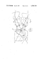
- FIG. 1 is the cross-section through I--I of FIG. 2 of the gear pump with tooth clearance
- FIG. 1a is a modified embodiment of the invention in the cross-section as in FIG. 1,
- FIG. 2 is the cross-section through II--II of FIG. 1,
- FIG. 3 is the cross-section through III--III of FIG. 2,
- FIG. 4 represents the relief grooves of a pair of helical spur gears with tooth clearance
- FIG. 5 shows the size of the relief area of a pair of straight spur gears, compared to a pair of helical spur gears as in FIG. 4 for a rotationangle ⁇ 1 of the driving gear
- FIG. 6 shows the size of the relief area of a pair of helical spur gears as in FIG. 4 with the same rotationangle ⁇ 1 as in FIG. 5,
- FIG. 7 is a modified embodiment of the relief grooves of FIG. 4,
- FIG. 8 shows the relief grooves of a pair of straight spur gears with no or nearly no tooth clearance
- FIG. 9 shows the relief grooves of a pair of helical spur gears with no or nearly no tooth clearance, said helical spur gears being comparable with the straight spur gears as in FIG. 8,
- FIG. 10 is the cross-section through III--III of FIG. 2, modified for a comparable pair of helical spur gears with no or nearly no tooth clearance,
- FIG. 11 is a modified embodiment of FIG. 9, viz. of the relief grooves at the leading lateral face of a pair of helical spur gears with no or nearly no tooth clearance and
- FIG. 12 is a modified embodiment of FIG. 9, viz. of the relief grooves at the lagging lateral face of a pair of helical spur gears with no or nearly no tooth clearance.
- FIGS. 1,2,3, The gear pump as shown in FIGS. 1,2,3, has a housing 1, that has been closed at both sides by coverplate 2 and 3. In the housing 1 there is a cylindrical aperture 4 that is formed by two intersecting bores 5 and 6. Aperture 4 has the shape of an eight. In bore 5 a driving helical spur gear 11 and two bearing bodies 7 and 8 with bearing bushes 9 and 10 have been positioned. In the same way in bore 6 the driven helical spur gear 16 and two bearing bodies 12 and 13 with bearing bushes 14 and 15 have been positioned.
- the gear pump conform FIG. 1a consists of a housing 1a with coverplate 2a.
- the helical spur gears 11 and 16 are pivoted by means of the concerning shafts in the housing 1a and coverplate 2a.
- the teeth of the driving helical spur gear are sloping rightward.
- the teeth of the driven helical spur gear are sloping leftward.
- the driving gear 11 rotates clockwise.
- relief grooves 19,20,21 and 22 have been positioned in the meshing area in such a way that (a) with decreasing volume of the enclosed tooth cavity the enclosed tooth cavity is connected with the pressure port via the relief grooves 19 and 21, which have been shifted over a distance V with respect to each other and that (b) with increasing volume of the enclosed tooth cavity the enclosed tooth cavity is connected with the suction port via the relief grooves 20 and 22, which have also been shifted over a distance V with respect to each other.
- the center distance extends from center M 1 of the driving helical spur gear 11 with right sloping teeth to center M 2 of the driven helical spur gear 16 with left sloping teeth.
- the thinly drawn line 23 represents the contours of the gears at the lagging lateral face 18 at the frontside of the helical gears.
- the thin dot-and-dash line 24 represents the contours of the gears at the leading lateral face 17 at the backside of the helical gears.
- the thick line 25 represents the contours of the helical gears in the transversal plane through the middle of the gears.
- the helical gears have been represented in a position, where the enclosed tooth cavity reaches its minimum volume or where the size of the shaded area of the enclosed tooth cavity 26, considered in the transversal plane through the middle of the gears, reaches its minimum. It is exact in this position, that the pressure commutation phenomenon takes place, i.e. the tooth cavity is cut off from the pressure port and is connected with the suction port.
- the relief grooves of the helical spur gears are dimensioned.
- the line of symmetry 88 belonging to the land edges 27, 28 has been shifted out of the plane through the two rotationaxes over a distance V/2 in the direction of the suction port and the line of symmetry 89 belonging to the land edges 32, 33 has been shifted out of the plane through the two rotation axes over a same distance V/2 in the direction of the pressureport.
- FIG. 3 are represented the relief grooves 19,21 and 20,22, which have been shifted over a distance V with respect to each other.
- the depth 36 of the relief grooves 19,20,21,22 is some millimeters and the width 37 of the relief grooves 19,20,21,22 is approximately the same as the tooth height.
- the relief grooves 19 and 20 or 21 and 22, positioned at the lateral faces of the helical spur gears are separated by a land having the width 38.
- the landwidth 38 has the same size as the landwidth 39 of a pair of straight spur gears with the identical transversal section (FIG. 5).
- the available relief areas of a pair of helical spur gears are shaded in FIG. 6 and the available relief areas of a pair of straight spur gears are shaded in FIG. 5.
- the relief area 40 is available at both lateral faces of the straight spur gears.
- the relief area 41 at the leading lateral face 17 and the relief area 42 at the lagging lateral face 18 are available. Furthermore there is available for relief the gap 43.
- the gear pump or gear motor with helical spur gears and the relief grooves 19,20,21,22, according to the invention has a larger relief area and for that reason a better relief of the toothcavity than the comparable gear pump or gear motor with straight gears.
- the relief grooves 19,20,21,22 at the lateral faces 17,18 of the helical spur gears may have a some what different shape.
- the relief grooves must always be dimensioned in such a way, that the enclosed tooth cavity is connected via the relief grooves 19,21, positioned at the side of the pressure port, with the pressure port, only with decreasing size of the area of the tooth cavity, considered in the transversal plane through the middle of the gears, and that the enclosed tooth cavity is connected via the relief grooves 20,22, positioned at the side of the suction port, with the suction port, only with increasing size of the area of the tooth cavity, considered in the transversal plane through the middle of the gears.
- the modified embodiment of the invention as shown in FIG. 7 is based on the somewhat rectangular relief grooves 19,20,21,22 with straight land edges 27,28,32,33.
- FIGS. 8 and 9 show, that the landwidth 77 is the same as the landwidth 54 of the comparable pair of straight spur gears with no or nearly no tooth clearance.
- the relief grooves In order to obtain a maximum relief area and an undisturbed pressure commutation, the relief grooves have to be dimensioned in such a way, that only with decreasing volume of an enclosed tooth cavity the enclosed tooth cavity is connected with the pressure port via the relief grooves 55 and 56, which have been shifted over a distance V with respect to each other, and that only with increasing volume of an enclosed tooth cavity the enclosed tooth cavity is connected with the suction port via the relief grooves 57 and 58, which have also been shifted over a distance V with respect to each other.
- the thin line 60 follows the contours of the helical gear at the lagging lateral face 61, at the front side of the helical gear.
- the thin dot-and-dash line 62 follows the contours of the helical gears at the leading lateral face 63 at the back side of the helical gears.
- the thick line 64 represents the contours of the helical gears in the transversal plane through the middle of the gears.
- the helical gears are represented in that position, where an enclosed toothcavity at the side of the driven gear reaches its minimal volume or in which the size of the shaded area 59 of the tooth cavity, considered in the transversal plane through the middle of the gears, is a minimum. It is exactly in this position, that the pressure commutation has to take place, i.e. the toothcavity is cut off from the pressure port and is connected with the suction port.
- the relief grooves 55,56,57,58 of the helical spur gears with no or nearly no tooth clearance are dimensioned.
- the straight land edges 65 and 66 of the somewhat rectangular relief grooves 56 and 58, positioned at the leading lateral face 63 of the helical gears in the background run parallel with the line of centers and through the two contact points 69 and 70, which are positioned on the pressure lines 68 and 67 (at the leading lateral face 63 in the background).
- the straight land edges 71 and 72, positioned at the lagging lateral face 61 of the helical gears in the foreground run parallel with the line of centers and through the two contact points 73 and 74, which are situated on the pressure lines 68 and 67 (in the lagging lateral face 61 in the foreground).
- the line of symmetry 90, belonging to the land edges 65, 66 has been shifted out of the plane through the two rotationaxes over a distance V/2 in the direction of the suction port and the line of symmetry y 1 , belonging to the land edges 71,72 has been shifted out of the plane through the two rotation axes over a distance V/2 in the direction of the pressure port.
- Depth 75 of the relief grooves 55,56,57,58 may be some millimeters.
- the width 76 of the relief grooves 55,56,57,58 equals approximately the tooth height.
- the relief grooves 56 and 58 or 55 and 57, positioned at the lateral face of the helical spur gears are separated by a land with width 77.
- the land with width 77 is unchanged compared to the landwidth 54 of a pair of straight spur gears with no or nearly no tooth clearance with the identical transversal section (FIG. 8).
- the relief grooves 55,56,57,58 at the lateral faces 61,63 of the helical spur gears may have a somewhat different shape.
- the relief grooves must always be dimensioned in such a way, that the enclosed tooth cavity, either at the side of the driving gear or at the side of the driven gear, is connected via the relief grooves 55,56, positioned at the side of the pressure port, with the pressure port, only with decreasing size of the area of the enclosed tooth cavity, considered in the transversal plane through the middle of the gears and that the enclosed tooth cavity, either at the side of the driving gear or at the side of the driven gear, is connected via the relief grooves 57,58, positioned at the side of the suction port, with the suction port, only with increasing size of the area of the enclosed tooth cavity, considered in the transversal plane through the middle of the gears.
- 11 and 12 is based on the somewhat rectangular relief grooves 55,56,57,58 with straight land edges 71,65,72,66.
- land somewhat triangular notches 79,81,82,84 have been formed which, starting from the intersection point of the land edges 71,65,72,66 with the pressure lines 67 and 68, follow the contours of the tooth flank along the foot in the direction of the most adjacent rootcircle 87 and of said rootcircle 87 for a rotation angle ⁇ 1 for which the size of the area of the enclosed tooth cavity at the side of the driven gear, considered in the transversal plane through the middle of the gears, reaches its minimum (FIGS. 11 and 12).
Landscapes
- Engineering & Computer Science (AREA)
- Mechanical Engineering (AREA)
- General Engineering & Computer Science (AREA)
- Rotary Pumps (AREA)
- Gears, Cams (AREA)
Applications Claiming Priority (2)
| Application Number | Priority Date | Filing Date | Title |
|---|---|---|---|
| DE2810563A DE2810563C2 (de) | 1978-03-10 | 1978-03-10 | Zahnradmaschine (Pumpe oder Motor) |
| DE2810563 | 1978-03-10 |
Publications (1)
| Publication Number | Publication Date |
|---|---|
| US4290739A true US4290739A (en) | 1981-09-22 |
Family
ID=6034123
Family Applications (1)
| Application Number | Title | Priority Date | Filing Date |
|---|---|---|---|
| US06/018,718 Expired - Lifetime US4290739A (en) | 1978-03-07 | 1979-03-08 | Helical gear pump or gear motor with optimal relief grooves for trapped fluid |
Country Status (3)
| Country | Link |
|---|---|
| US (1) | US4290739A (de) |
| EP (1) | EP0004120B1 (de) |
| DE (1) | DE2810563C2 (de) |
Cited By (28)
| Publication number | Priority date | Publication date | Assignee | Title |
|---|---|---|---|---|
| US4548562A (en) * | 1982-09-07 | 1985-10-22 | Ford Motor Company | Helical gear pump with specific helix angle, tooth contact length and circular base pitch relationship |
| US4824331A (en) * | 1987-07-29 | 1989-04-25 | Hydreco, Incorporated | Variable discharge gear pump with energy recovery |
| US5131829A (en) * | 1991-06-19 | 1992-07-21 | Eaton Corporation | Trapped volume vent means for meshing lobes of roots-type supercharger |
| US5733111A (en) * | 1996-12-02 | 1998-03-31 | Ford Global Technologies, Inc. | Gerotor pump having inlet and outlet relief ports |
| US5865239A (en) * | 1997-02-05 | 1999-02-02 | Micropump, Inc. | Method for making herringbone gears |
| US6042352A (en) * | 1998-08-12 | 2000-03-28 | Argo-Tech Corporation | Bearing with pulsed bleed configuration |
| US6312241B1 (en) * | 1999-09-06 | 2001-11-06 | Koyo Seiko Co., Ltd. | Gear pump |
| WO2002027186A1 (en) * | 2000-09-27 | 2002-04-04 | Rpm Industries, Inc. | Improved engine prelubrication pump assembly |
| US20040045609A1 (en) * | 1997-10-30 | 2004-03-11 | John Apostolides | Vehicle fluid change apparatus |
| US20040211470A1 (en) * | 1997-10-30 | 2004-10-28 | Apostolides John K. | Methods and systems for performing, monitoring and analyzing multiple machine fluid processes |
| US6853954B2 (en) | 2002-09-24 | 2005-02-08 | John K. Apostolides | Methods and systems for collecting and processing data in association with machine operation and maintenance |
| US20050173004A1 (en) * | 1997-10-30 | 2005-08-11 | Apostolides John K. | Methods and systems for performing, monitoring and analyzing multiple machine fluid processes |
| US6988506B1 (en) | 1997-10-30 | 2006-01-24 | Rpm Industries, Inc. | Fluid transfer system |
| US20070178003A1 (en) * | 2005-11-22 | 2007-08-02 | Parker-Hannifin Corporation | Gear pump with ripple chamber for low noise and pressure ripples |
| US20070201989A1 (en) * | 2005-10-14 | 2007-08-30 | Parker-Hannifin | Low ripple gear pump/motor |
| US20080063554A1 (en) * | 2006-09-08 | 2008-03-13 | Gifford Thomas K | Precision flow gear pump |
| WO2008111017A1 (en) * | 2007-03-14 | 2008-09-18 | Settima Meccanica S.R.L. | Improved geared hydraulic apparatus |
| US20090060770A1 (en) * | 2005-02-24 | 2009-03-05 | Shimadzu Mectem, Inc. | Gear pump |
| US20090089168A1 (en) * | 2007-01-10 | 2009-04-02 | Phyllis Adele Schneck | ACE (Alternative Currency Exchange): Alternative Currency Tracking and Mapping System and Method |
| US20090148333A1 (en) * | 2007-12-11 | 2009-06-11 | Hamilton Sundstrand Corporation | Gear pump cavitation reduction |
| US8801410B2 (en) | 2011-02-25 | 2014-08-12 | Hamilton Sundstrand Corporation | Coupling shaft for gear pump |
| US8814547B2 (en) | 2011-02-25 | 2014-08-26 | Hamilton Sundstrand Corporation | Seal retaining sleeve for gear pump |
| US8911222B2 (en) | 2011-02-25 | 2014-12-16 | Hamilton Sundstrand Corporation | Input shaft assembly for gear pump |
| US8992192B2 (en) | 2011-02-25 | 2015-03-31 | Hamilton Sundstrand Corporation | Input shaft lubrication for gear pump |
| WO2015080765A1 (en) * | 2013-11-26 | 2015-06-04 | Woodward, Inc. | Gear pump bearing dam |
| US9677559B2 (en) | 2011-02-25 | 2017-06-13 | Hamilton Sundstrand Corporation | Bearing face geometry for gear pump |
| US10443597B2 (en) | 2016-01-12 | 2019-10-15 | Hamilton Sundstrand Corporation | Gears and gear pumps |
| US10563653B2 (en) | 2016-01-12 | 2020-02-18 | Hamilton Sundstrand Corporation | Gear pump |
Families Citing this family (4)
| Publication number | Priority date | Publication date | Assignee | Title |
|---|---|---|---|---|
| DE4040409C1 (de) * | 1990-12-18 | 1992-05-14 | Vse Schweisstechnik Gmbh, 5982 Neuenrade, De | |
| GB2313627A (en) * | 1996-05-29 | 1997-12-03 | Roy William Masters | Rotary engine |
| DE102015201961A1 (de) | 2015-02-04 | 2016-08-04 | Volkswagen Aktiengesellschaft | Verfahren zum Betrieb einer Verdrängerpumpe sowie eine hierfür bestimmte Verdrängerpumpe |
| DE102020100241A1 (de) | 2020-01-08 | 2021-07-08 | Thyssenkrupp Ag | Verfahren zur Herstellung von Phosphorsäure und Klinkerprozess-geeigneter Kalziumsulfatqualität zur kommerziellen und industriellen Verwertung von Kalziumsulfat |
Citations (8)
| Publication number | Priority date | Publication date | Assignee | Title |
|---|---|---|---|---|
| US1129090A (en) * | 1914-04-08 | 1915-02-23 | American La France Fire Engine Company Inc | Gear-pump. |
| US1233069A (en) * | 1916-05-22 | 1917-07-10 | Leonard Pump And Motor Co | Pump and liquids. |
| US1634023A (en) * | 1927-06-28 | Ptjmp | ||
| US1706829A (en) * | 1928-05-28 | 1929-03-26 | Joseph Mercadante | Pump |
| US2147405A (en) * | 1935-01-05 | 1939-02-14 | Trico Products Corp | Motor vehicle power plant |
| US2338065A (en) * | 1940-06-13 | 1943-12-28 | Joseph F Keller | Gear pump |
| US2354992A (en) * | 1941-11-11 | 1944-08-01 | Westinghouse Electric & Mfg Co | Gear pump |
| US2884864A (en) * | 1955-04-14 | 1959-05-05 | Borg Warner | Pressure loaded pump, trapping grooves |
Family Cites Families (7)
| Publication number | Priority date | Publication date | Assignee | Title |
|---|---|---|---|---|
| US2136142A (en) * | 1935-06-25 | 1938-11-08 | American Viscose Corp | Rayon-spinning pump |
| US2781730A (en) * | 1952-10-22 | 1957-02-19 | Thompson Prod Inc | Implement pump |
| CH399193A (de) * | 1960-08-18 | 1966-03-31 | Reiners & Wiggermann | Verstell-Zahnradpumpe |
| FR1355756A (fr) * | 1963-02-07 | 1964-03-20 | Johannes Freres | Pompe à engrenage perfectionnée destinée plus particulièrement aux engins de travaux publics |
| DE2249952C3 (de) * | 1972-10-12 | 1975-03-27 | Zahnradfabrik Friedrichshafen Ag, 7990 Friedrichshafen | Hydraulische Zahnradmaschine |
| DE2623357A1 (de) * | 1976-05-25 | 1977-12-15 | Bosch Gmbh Robert | Zahnradmaschine (pumpe oder motor) |
| DE2701303C3 (de) * | 1977-01-14 | 1983-02-17 | Zahnradfabrik Friedrichshafen Ag, 7990 Friedrichshafen | Hydraulische Zahnradmaschine |
-
1978
- 1978-03-10 DE DE2810563A patent/DE2810563C2/de not_active Expired
-
1979
- 1979-03-08 US US06/018,718 patent/US4290739A/en not_active Expired - Lifetime
- 1979-03-09 EP EP79200119A patent/EP0004120B1/de not_active Expired
Patent Citations (8)
| Publication number | Priority date | Publication date | Assignee | Title |
|---|---|---|---|---|
| US1634023A (en) * | 1927-06-28 | Ptjmp | ||
| US1129090A (en) * | 1914-04-08 | 1915-02-23 | American La France Fire Engine Company Inc | Gear-pump. |
| US1233069A (en) * | 1916-05-22 | 1917-07-10 | Leonard Pump And Motor Co | Pump and liquids. |
| US1706829A (en) * | 1928-05-28 | 1929-03-26 | Joseph Mercadante | Pump |
| US2147405A (en) * | 1935-01-05 | 1939-02-14 | Trico Products Corp | Motor vehicle power plant |
| US2338065A (en) * | 1940-06-13 | 1943-12-28 | Joseph F Keller | Gear pump |
| US2354992A (en) * | 1941-11-11 | 1944-08-01 | Westinghouse Electric & Mfg Co | Gear pump |
| US2884864A (en) * | 1955-04-14 | 1959-05-05 | Borg Warner | Pressure loaded pump, trapping grooves |
Cited By (43)
| Publication number | Priority date | Publication date | Assignee | Title |
|---|---|---|---|---|
| US4548562A (en) * | 1982-09-07 | 1985-10-22 | Ford Motor Company | Helical gear pump with specific helix angle, tooth contact length and circular base pitch relationship |
| US4824331A (en) * | 1987-07-29 | 1989-04-25 | Hydreco, Incorporated | Variable discharge gear pump with energy recovery |
| US5131829A (en) * | 1991-06-19 | 1992-07-21 | Eaton Corporation | Trapped volume vent means for meshing lobes of roots-type supercharger |
| US5733111A (en) * | 1996-12-02 | 1998-03-31 | Ford Global Technologies, Inc. | Gerotor pump having inlet and outlet relief ports |
| US5865239A (en) * | 1997-02-05 | 1999-02-02 | Micropump, Inc. | Method for making herringbone gears |
| US6544008B1 (en) * | 1997-07-18 | 2003-04-08 | John K. Apostolides | Internal vent for reducing seal pressure in prelubrication pump assembly |
| US7793681B2 (en) | 1997-10-30 | 2010-09-14 | RPM Industries, LLC | Methods and systems for performing, monitoring and analyzing multiple machine fluid processes |
| US9062575B2 (en) | 1997-10-30 | 2015-06-23 | RPM Industries, LLC | Methods and systems for performing, monitoring and analyzing multiple machine fluid processes |
| US20070113894A1 (en) * | 1997-10-30 | 2007-05-24 | Rpm Industries, Inc. | Methods and systems for performing, monitoring and analyzing multiple machine fluid processes |
| US20040045609A1 (en) * | 1997-10-30 | 2004-03-11 | John Apostolides | Vehicle fluid change apparatus |
| US20040211470A1 (en) * | 1997-10-30 | 2004-10-28 | Apostolides John K. | Methods and systems for performing, monitoring and analyzing multiple machine fluid processes |
| US20050173004A1 (en) * | 1997-10-30 | 2005-08-11 | Apostolides John K. | Methods and systems for performing, monitoring and analyzing multiple machine fluid processes |
| US6941969B2 (en) | 1997-10-30 | 2005-09-13 | Rpm Industries, Inc. | Vehicle fluid change apparatus |
| US6988506B1 (en) | 1997-10-30 | 2006-01-24 | Rpm Industries, Inc. | Fluid transfer system |
| US7150286B2 (en) | 1997-10-30 | 2006-12-19 | Rpm Industries, Inc. | Methods and systems for performing, monitoring and analyzing multiple machine fluid processes |
| US6042352A (en) * | 1998-08-12 | 2000-03-28 | Argo-Tech Corporation | Bearing with pulsed bleed configuration |
| US6312241B1 (en) * | 1999-09-06 | 2001-11-06 | Koyo Seiko Co., Ltd. | Gear pump |
| WO2002027186A1 (en) * | 2000-09-27 | 2002-04-04 | Rpm Industries, Inc. | Improved engine prelubrication pump assembly |
| US6853954B2 (en) | 2002-09-24 | 2005-02-08 | John K. Apostolides | Methods and systems for collecting and processing data in association with machine operation and maintenance |
| US20090060770A1 (en) * | 2005-02-24 | 2009-03-05 | Shimadzu Mectem, Inc. | Gear pump |
| US20070201989A1 (en) * | 2005-10-14 | 2007-08-30 | Parker-Hannifin | Low ripple gear pump/motor |
| US20070178003A1 (en) * | 2005-11-22 | 2007-08-02 | Parker-Hannifin Corporation | Gear pump with ripple chamber for low noise and pressure ripples |
| US20080063554A1 (en) * | 2006-09-08 | 2008-03-13 | Gifford Thomas K | Precision flow gear pump |
| US20090089168A1 (en) * | 2007-01-10 | 2009-04-02 | Phyllis Adele Schneck | ACE (Alternative Currency Exchange): Alternative Currency Tracking and Mapping System and Method |
| WO2008111017A1 (en) * | 2007-03-14 | 2008-09-18 | Settima Meccanica S.R.L. | Improved geared hydraulic apparatus |
| CN101790622B (zh) * | 2007-03-14 | 2015-03-25 | 瑟提马麦肯尼加有限公司 | 改进型齿轮式液压装置 |
| US8556609B2 (en) | 2007-03-14 | 2013-10-15 | Mario Antonio Morselli | Geared hydraulic apparatus |
| US20100104463A1 (en) * | 2007-03-14 | 2010-04-29 | Settima Meccanica S.R.L. | Geared hydraulic apparatus |
| US7878781B2 (en) * | 2007-12-11 | 2011-02-01 | Hamilton Sundstrand Corporation | Gear pump cavitation reduction |
| US20090148333A1 (en) * | 2007-12-11 | 2009-06-11 | Hamilton Sundstrand Corporation | Gear pump cavitation reduction |
| US9546655B2 (en) | 2011-02-25 | 2017-01-17 | Hamilton Sundstrand Corporation | Coupling shaft for gear pump |
| US8911222B2 (en) | 2011-02-25 | 2014-12-16 | Hamilton Sundstrand Corporation | Input shaft assembly for gear pump |
| US8992192B2 (en) | 2011-02-25 | 2015-03-31 | Hamilton Sundstrand Corporation | Input shaft lubrication for gear pump |
| US8814547B2 (en) | 2011-02-25 | 2014-08-26 | Hamilton Sundstrand Corporation | Seal retaining sleeve for gear pump |
| US8801410B2 (en) | 2011-02-25 | 2014-08-12 | Hamilton Sundstrand Corporation | Coupling shaft for gear pump |
| US9677559B2 (en) | 2011-02-25 | 2017-06-13 | Hamilton Sundstrand Corporation | Bearing face geometry for gear pump |
| US10024319B2 (en) | 2011-02-25 | 2018-07-17 | Hamilton Sundstrand Corporation | Method for lubricating a coupling shaft for gear pump |
| WO2015080765A1 (en) * | 2013-11-26 | 2015-06-04 | Woodward, Inc. | Gear pump bearing dam |
| US9303644B2 (en) | 2013-11-26 | 2016-04-05 | Woodward, Inc. | Gear pump bearing dam |
| CN105917119A (zh) * | 2013-11-26 | 2016-08-31 | 伍德沃德有限公司 | 齿轮泵轴承坝 |
| US9932980B2 (en) | 2013-11-26 | 2018-04-03 | Woodward, Inc. | Gear pump bearing dam |
| US10443597B2 (en) | 2016-01-12 | 2019-10-15 | Hamilton Sundstrand Corporation | Gears and gear pumps |
| US10563653B2 (en) | 2016-01-12 | 2020-02-18 | Hamilton Sundstrand Corporation | Gear pump |
Also Published As
| Publication number | Publication date |
|---|---|
| EP0004120A2 (de) | 1979-09-19 |
| DE2810563C2 (de) | 1982-10-28 |
| DE2810563A1 (de) | 1979-09-13 |
| EP0004120B1 (de) | 1983-04-06 |
| EP0004120A3 (en) | 1979-10-03 |
Similar Documents
| Publication | Publication Date | Title |
|---|---|---|
| US4290739A (en) | Helical gear pump or gear motor with optimal relief grooves for trapped fluid | |
| US2319374A (en) | Balanced pump and motor | |
| US3834842A (en) | Hydraulic power translating device | |
| US4548562A (en) | Helical gear pump with specific helix angle, tooth contact length and circular base pitch relationship | |
| US3303792A (en) | Gear pump with trapping reliefs | |
| GB1467441A (en) | Hydraulic gear pumps and motors | |
| US4233005A (en) | Hydraulic gear pump with recesses in non-working gear flanks | |
| US5733111A (en) | Gerotor pump having inlet and outlet relief ports | |
| US4130383A (en) | Apparatus for noise suppression in a gear pump | |
| US3113524A (en) | Gear pump with trapping reliefs | |
| US1129090A (en) | Gear-pump. | |
| US4470768A (en) | Rotary vane pump, in particular for assisted steering | |
| US3291060A (en) | Gear pumps | |
| US3130682A (en) | Gear pump | |
| US3286643A (en) | Gear pumps and motors | |
| US4132515A (en) | Crescent gear pump or motor having bearing means for supporting the ring gear | |
| DE2132465A1 (de) | Hydraulischer Fluegelradwandler | |
| US3171359A (en) | Hydraulically unbalanced wear plate | |
| US3306228A (en) | Combination gear and vane pump | |
| JPH03202686A (ja) | 歯車ポンプ | |
| US5135373A (en) | Spur gear with epi-cycloidal and hypo-cycloidal tooth shapes | |
| CA1103989A (en) | Geared pump | |
| JP2787706B2 (ja) | 歯車ポンプ | |
| GB1308295A (en) | Liquid pump or motor | |
| US4368013A (en) | Gear motor with fluid pressure groove and recess to facilitate starting |
Legal Events
| Date | Code | Title | Description |
|---|---|---|---|
| STCF | Information on status: patent grant |
Free format text: PATENTED CASE |