US4359331A - Contactor-separator units - Google Patents
Contactor-separator units Download PDFInfo
- Publication number
- US4359331A US4359331A US05/901,082 US90108278A US4359331A US 4359331 A US4359331 A US 4359331A US 90108278 A US90108278 A US 90108278A US 4359331 A US4359331 A US 4359331A
- Authority
- US
- United States
- Prior art keywords
- contactor
- sub
- assembly
- separator
- phase
- Prior art date
- Legal status (The legal status is an assumption and is not a legal conclusion. Google has not performed a legal analysis and makes no representation as to the accuracy of the status listed.)
- Expired - Lifetime
Links
- 239000012530 fluid Substances 0.000 claims description 6
- 238000000605 extraction Methods 0.000 claims description 5
- 238000005086 pumping Methods 0.000 claims description 4
- 230000000155 isotopic effect Effects 0.000 abstract description 19
- 239000012074 organic phase Substances 0.000 description 43
- 239000008346 aqueous phase Substances 0.000 description 37
- 239000012071 phase Substances 0.000 description 23
- 238000000429 assembly Methods 0.000 description 14
- 238000009434 installation Methods 0.000 description 13
- 239000011159 matrix material Substances 0.000 description 9
- 238000000926 separation method Methods 0.000 description 9
- 229910052770 Uranium Inorganic materials 0.000 description 7
- JFALSRSLKYAFGM-UHFFFAOYSA-N uranium(0) Chemical compound [U] JFALSRSLKYAFGM-UHFFFAOYSA-N 0.000 description 6
- XLYOFNOQVPJJNP-ZSJDYOACSA-N Heavy water Chemical compound [2H]O[2H] XLYOFNOQVPJJNP-ZSJDYOACSA-N 0.000 description 4
- 239000007788 liquid Substances 0.000 description 3
- 238000010586 diagram Methods 0.000 description 2
- 238000005372 isotope separation Methods 0.000 description 2
- 238000000034 method Methods 0.000 description 2
- 238000005192 partition Methods 0.000 description 2
- 239000000126 substance Substances 0.000 description 2
- XLYOFNOQVPJJNP-UHFFFAOYSA-N water Substances O XLYOFNOQVPJJNP-UHFFFAOYSA-N 0.000 description 2
- 238000005516 engineering process Methods 0.000 description 1
- 239000011872 intimate mixture Substances 0.000 description 1
- 239000007791 liquid phase Substances 0.000 description 1
- 238000012544 monitoring process Methods 0.000 description 1
- 239000003758 nuclear fuel Substances 0.000 description 1
- 238000011084 recovery Methods 0.000 description 1
- 230000003068 static effect Effects 0.000 description 1
- 238000011144 upstream manufacturing Methods 0.000 description 1
Images


Classifications
-
- B—PERFORMING OPERATIONS; TRANSPORTING
- B01—PHYSICAL OR CHEMICAL PROCESSES OR APPARATUS IN GENERAL
- B01D—SEPARATION
- B01D11/00—Solvent extraction
- B01D11/04—Solvent extraction of solutions which are liquid
-
- B—PERFORMING OPERATIONS; TRANSPORTING
- B01—PHYSICAL OR CHEMICAL PROCESSES OR APPARATUS IN GENERAL
- B01D—SEPARATION
- B01D59/00—Separation of different isotopes of the same chemical element
- B01D59/22—Separation by extracting
-
- B—PERFORMING OPERATIONS; TRANSPORTING
- B01—PHYSICAL OR CHEMICAL PROCESSES OR APPARATUS IN GENERAL
- B01J—CHEMICAL OR PHYSICAL PROCESSES, e.g. CATALYSIS OR COLLOID CHEMISTRY; THEIR RELEVANT APPARATUS
- B01J19/00—Chemical, physical or physico-chemical processes in general; Their relevant apparatus
- B01J19/32—Packing elements in the form of grids or built-up elements for forming a unit or module inside the apparatus for mass or heat transfer
-
- B—PERFORMING OPERATIONS; TRANSPORTING
- B01—PHYSICAL OR CHEMICAL PROCESSES OR APPARATUS IN GENERAL
- B01J—CHEMICAL OR PHYSICAL PROCESSES, e.g. CATALYSIS OR COLLOID CHEMISTRY; THEIR RELEVANT APPARATUS
- B01J2219/00—Chemical, physical or physico-chemical processes in general; Their relevant apparatus
- B01J2219/32—Details relating to packing elements in the form of grids or built-up elements for forming a unit of module inside the apparatus for mass or heat transfer
- B01J2219/322—Basic shape of the elements
- B01J2219/32282—Rods or bars
Definitions
- the present invention relates to subassemblies of contactor-separator units suitable for use in liquid-liquid or gas-liquid exchange or extraction apparatus.
- each elementary contact-separation sequence provides an enrichment, however, with a low partition coefficient, whereby a large number of operations is necessary for achieving the desired enrichment.
- a large number of contactor-separator units is consequently necessary, in which counter-current flows of two phases occur.
- one pump for each stage or unit is provided, resulting in high investment and maintainance costs as well as difficult monitoring and control.
- a sub-assembly for an exchange or extraction apparatus between a first and a second mutually immiscible fluid phases, typically under such conditions that the net mass transfer between the two phases is small as compared with the instantaneous rates of flow of the phases comprising: m ⁇ n contactor-separator units located in a matrix arrangement of m lines and n columns, means for directing flows of the first phase to the first contactor-separator units of respective ones of said lines and directing the flow of said first phase from the outlet of each said contactor-separator unit to the inlet of the next contactor-separator unit of the same line, means for directing flows of the second phase to the first contactor-separator units of respective ones of said columns and for directing the flow of said second phase from each contactor-separator unit to the next contactor-separator unit of the same column, and m+n pumping units each associated with a corresponding line or column,
- the contactor-separator units may be of any one of a number of conventional types. For instance, each may be a static mixer followed by a settler.
- the pumping means may be of any type providing the necessary rate of flow and pressure increase. No difficulty will be involved since the head loss impressed by a mixer-settler is typically of about 50 cm of water head.
- the sub-assembly comprises m ⁇ n contactor-separator units in a matrix or "crossed" arrangement. Since a single pump per line and per column ensures the flow for each phase, the total number of pumps is m+n.
- the partition coefficient will typically be very low, for instance for the separation of uranium isotopes; it is then necessary to have a large number of contactor-separator units to achieve the isotopic enrichment which is frequently required. Then, an installation will generally be used which comprises a plurality of sub-assemblies each having m ⁇ n contactor-separator units.
- the number of lines and columns of the assembly may be equal or different, leading to a "square matrix” or “rectangular matrix” structure.
- One or more contactor-separator sub-assembly(ies) according to the invention can also be used in the chemical or petrochemical industry, the re-processing of spent nuclear fuels as well as for isotopic enrichment of uranium.
- FIGS. 1 and 2 are most simplified block diagrams of a sub-assembly of contactor-separator units for an isotopic enrichment installation, FIGS. 1 and 2 respectively providing indications on the pressures and enrichments;
- FIGS. 3, 4 and 5 are simplified block diagrams of an installation having two sub-assemblies of the general type shown in FIGS. 1 and 2, a head end sub-assembly and a tail end sub-assembly, FIGS. 3, 4 and 5 respectively providing indications on the organic phase enrichment, aqueous phase depletion and distribution of pressures;
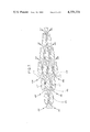
- FIG. 6 is a sketch illustrating a possible spatial arrangement of the contactor-separator units of a sub-assembly
- FIG. 7 is a simplified elevational view of an arrangement of contactor-separator units.
- a sub-assembly 1 comprising twelve contactor-separator units numbered from 3a to 3l.
- each contactor-separator unit there takes place an elementary operation, namely successive mixing and separation of the two phases.
- the contactor-separator units may be of any conventional type, for instance mixer-settlers.
- the sub-assembly of FIG. 1 is connected with other sub-assemblies located upstream and/or downstream in the direction of flow of the organic phase, for constituting an enrichment installation, by pipe means which will be referred to later.
- the pressure of the organic phase coming from the preceding sub-assembly at pressure P+3p is increased by pump 5 to pressure P+7p.
- the organic phase flows in contactor-separator unit 3a in counter-current with an aqueous phase coming from the following sub-assembly through pipe 17.
- the aqueous phase is also at pressure P+7p, owing to pump 27 which brought up its pressure from P+4p to P+7p.
- the two phases leave contactor-separator units 3a via separate outlets and are respectively delivered to contactor-separator units 3b and 3e under identical pressures equal to P+6p.
- contactor-separator unit 3b the organic phase again flows in counter-current with an aqueous phase coming through 19 from the following sub-assembly at a pressure which is adjusted at P+6p. After separation, the organic and aqueous phases, both at pressure P+5 p, leave contactor-separator unit 3b and are directed to adjacent contactor-separator units 3c and 3f, respectively.
- the organic phase entering contactor-separator unit 3c is contacted with an aqueous phase coming, through pipe 21, from the following sub-assembly and at a pressure increased from P+2p to P+5p by pump 31.
- the two phases which leave contactor-separator unit 3c by separate outlets are directed to adjacent contactor-separator units 3d and 3g are both at pressure P+4p.
- the organic phase is successively mixed with and separated from an aqueous phase coming from the following sub-assembly through 23 at a pressure increased to P+4p by pump 33.
- the organic phase is directed towards the following sub-assembly by pipe 35.
- a pump (not shown) is provided for raising the pressure in the first line of the sub-assembly by 4 p if the following sub-assembly also comprises four contactor-separator units per line.
- the aqueous phase which leaves contactor-separator unit 3a at pressure P+6p is directed to the next contactor-separator unit 3e in the same column where it meets an organic phase coming from the preceding sub-assembly through 13 and at pressure P+6p.
- the aqueous and organic phases are separated and respectively directed to contactor-separator units 3i and 3f at a pressure equal to P+5p.
- the aqueous and organic phases coming from 3e and from the preceding sub-assembly at pressure P+5p are mixed, separated and sent, at a pressure lowered to P+4p, to the preceding sub-assembly for the aqueous phase and to the contactor-separator unit 3j for the organic phase.
- a pump (not shown) in pipe 37 raises the pressure of the aqueous phase before it enters the preceding sub-unit.
- FIG. 2 there is shown the same sub-assembly as in FIG. 1 with however the contactor-separator units illustrated as dots at the line-column crossings and with indication of the enrichment in a particular isotope (or solute) rather than of the pressures.
- the deviation i.e. the ratio between the molar ratios at the outputs of a unit
- the deviation will be approximately 4 ⁇ .x (assuming that x and ⁇ are much smaller than 1).
- Sub-assembly 1 which is one of the numerous similar sub-assemblies of a isotopic separation plant, is represented as comprising twelve contactor-separator units 3. Lines 11, 13 and 15 are each fed with a flow rate V/3 of organic phases coming from the preceding sub-assembly through pumps 5, 7 and 9 respectively.
- Four pumps 27, 29, 31 and 33 each introduce a flow rate L/4 of aqueous phases originating from the following sub-assembly of the plant, into a respective column 17, 19, 21 or 23.
- L and V are substantially constant.
- the organic phase going into contactor-separator unit 3a contains uranium with a isotopic molar fraction (also designated as isotopic abundance) x.
- unit 3a it contacts an aqueous phase coming from the following sub-assembly through 17 at the isotopic abundance x(1+3 ⁇ ). Since the organic phase becomes isotopically enriched, the isotopic abundances in the aqueous and organic phases at the output of 3a will respectively be x(1- ⁇ ) and x(1+3 ⁇ ).
- the enrichment provided by each contactor-separator unit is characterized by a deviation 4 ⁇ .x between the outputs.
- the isotopic enrichments will evolve in the sub-assembly according to the enrichment chart which is shown in FIG. 2.
- FIGS. 3, 4 and 5 there is schematically shown an installation for isotopic enrichment of uranium by liquid-liquid chemical exchange, having two sub-assemblies (representative of the much larger number of such sub-assemblies necessary in an actual installation), one input or head sub-assembly and one output or tail sub-assembly, with complete reflow.
- Sub-assemblies 50 and 52 are each formed from nine contactor-separator units 54, associated in a "square matrix" structure.
- the input sub-assembly of the organic phase 56 only comprises six contactor-separator units associated in a triangular arrangement which allows the three lines 58, 60 and 62 to be supplied with organic phases at an identical isotopic abundance, i.e. x (x being the lowest isotopic abundance at the input of the installation) corresponding, for instance, to natural U.
- the output sub-assembly 64 from which the organic phase flows out, also has six contactor-separator units disposed in a triangular arrangement so that flows of organic phase having the same isotopic abundance x (1+10 ⁇ ) are delivered at the output of each line (the enrichment provided by each contactor-separator unit corresponding to a deviation ⁇ .x between its outputs).
- the flows of aqueous phase move in counter-current in relation to the flows of organic phases, in columns 66, 68 and 70 of sub-assembly 64 and then in the columns of the other sub-assemblies up to sub-assembly 56 inclusive.
- the aqueous phases have an isotopic abundance equal to x(1+10) in each column at their inputs into the installation. At the outputs, the isotopic abundances have dropped to x.
- the four sub-assemblies are associated in series; ends A, B, C of lines 58, 60 and 62, at the output of sub-assembly 50, are connected to ends D, E, F of the same lines 58, 60 and 62 of sub-assembly 52.
- the outputs G, H, I of columns 66, 68, 70 leaving sub-assembly 52 are connected to the ends J, K, L of the same columns 66, 68, 70 of sub-assembly 50.
- the flow of the two phases and the compensation for pressure losses are achieved by pumps, 72 for example, placed in lines and columns in accordance with the invention.
- FIG. 3 the chart of the organic phase enrichments
- FIG. 4 the aqueous phase depletions
- FIG. 5 the distribution of the pressures in the installation.
- each of the sub-assemblies shown in perspective, comprises sixteen contactor-separator units, disposed in four lines and four columns (74 to 89 for sub-assembly A and 90 to 105 for sub-assembly B).
- the contactor-separator units are distributed over a cylindrical surface. They could as well be placed along any vertical prismatic surface having, for instance, a triangular, square or hexagonal base.
- This arrangement is compact, spares room and appreciably reduces the length of the lines connecting the different components.
- an aqueous phase coming from an upper sub-assembly (not shown) enters the first line of sub-assembly B through contactor-separator unit 105.
- contactor-separator unit 89 the first contactor-separator unit of the four units 89, 85, 81 and 77 forming the first line of sub-assembly A.
- the aqueous phase leaves contactor-separator unit 77 to go, after passing through pump 109, to a lower sub-assembly (not shown).
- an aqueous phase coming from the upper sub-assembly B enters the second line of sub-assembly B through contactor-separator 104, leaves it, after exchange with organic phases in contactor-separator units 104, 100, 96 and 92, and is delivered to contactor-separator unit 88 of the second line of sub-assembly A. After passing through this second line, the aqueous phase is directed towards the lower sub-assembly. The same occurs for all the other lines of the different sub-assemblies forming the installation.
- the organic phases (shown with full lines) "go up" into the columns of sub-assemblies A and B.
- column 111 for example, an organic phase brought to the required pressure by pump 113, flows, for exchange with aqueous phases, in contactor-separator units 82, 83, 84, 85 of sub-assembly A.
- Pump 115 placed at the input of sub-assembly B, raises the pressure of the organic phase before it passes into contactor-separator units 98, 99, 100 and 101 of sub-assembly B.
- the flow of the organic phases in the other columns takes place in an identical manner.
- FIG. 7 there is shown a vertical cross-section of part of a contactor-separator sub-assembly located in a right parallelepipedic casing (not shown) provided with apertures for the ingoing and outgoing phases, inside which a plurality of obstacles, formed by right prismatic blocks having horizontal edges, shown in cross-section, are placed in staggered relation and cooperate to limit passages between the inputs and the outputs of the phases.
- Each pair of adjacent blocks forms a passage in which there successively occurs mixing and separation of the phases.
- the sub-assembly shown in this figure comprises nine contactor-separator units associated in three lines and three columns, in accordance with the invention, the flow of the aqueous phase being shown with chain-dotted lines and that of the organic phases by full lines.
- Fourteen prismatic blocks 115 define with the walls of the enclosure the passages for the two phases. These blocks are cut out so that assembled two by two they form one contactor-separator unit; the intake part 121 provides mixing of the phases whereas settling takes place in section 123 of the passage.
- Three pumps disposed at the inputs of aqueous phases 125, 127 and 129, and three pumps placed at the inputs of organic phases 131, 133 and 135 deliver the two phases into the sub-assembly.
- the aqueous phase circulating as indicated at 125 and the organic phase indicated at 131 are mixed in 121, then separated in 123.
- the organic phase penetrates into the next contactor-separator unit where, at 121', it meets the aqueous phase entering through 127, whereas the aqueous phase flows into 121" where it is mixed with the organic phase arriving through 133.
- the progress of the phases is shown by full lines and chain-dotted lines, respectively. They leave the sub-unit through outlets 137 to 147 to be directed towards another sub-assembly.
- each passage may have a thickness of some centimeters in the throttled portion and the corresponding flow velocity may be of about 1 m/sec.
Landscapes
- Chemical & Material Sciences (AREA)
- Chemical Kinetics & Catalysis (AREA)
- Physics & Mathematics (AREA)
- Thermal Sciences (AREA)
- Organic Chemistry (AREA)
- Extraction Or Liquid Replacement (AREA)
Applications Claiming Priority (2)
| Application Number | Priority Date | Filing Date | Title |
|---|---|---|---|
| FR7713644 | 1977-04-29 | ||
| FR7713644A FR2388591A1 (fr) | 1977-04-29 | 1977-04-29 | Assemblage de contacteurs-separateurs dans une installation d'extraction |
Publications (1)
| Publication Number | Publication Date |
|---|---|
| US4359331A true US4359331A (en) | 1982-11-16 |
Family
ID=9190363
Family Applications (1)
| Application Number | Title | Priority Date | Filing Date |
|---|---|---|---|
| US05/901,082 Expired - Lifetime US4359331A (en) | 1977-04-29 | 1978-04-28 | Contactor-separator units |
Country Status (7)
| Country | Link |
|---|---|
| US (1) | US4359331A (fr) |
| JP (1) | JPS5832611B2 (fr) |
| AU (1) | AU520408B2 (fr) |
| CA (1) | CA1110043A (fr) |
| DE (1) | DE2818924A1 (fr) |
| FR (1) | FR2388591A1 (fr) |
| IT (1) | IT1095262B (fr) |
Cited By (2)
| Publication number | Priority date | Publication date | Assignee | Title |
|---|---|---|---|---|
| RU2201283C1 (ru) * | 2001-11-21 | 2003-03-27 | Федеральное государственное унитарное предприятие "Производственное объединение "Маяк" | Способ разделения изотопов водорода |
| US20040060441A1 (en) * | 2000-11-29 | 2004-04-01 | Juanico Luis Eduardo | Gaseous diffusion enrichment modular unit |
Families Citing this family (1)
| Publication number | Priority date | Publication date | Assignee | Title |
|---|---|---|---|---|
| JPS57182308A (en) * | 1981-05-02 | 1982-11-10 | Sumitomo Naugatuck Co Ltd | Production of copolymer |
Citations (7)
| Publication number | Priority date | Publication date | Assignee | Title |
|---|---|---|---|---|
| US676209A (en) * | 1896-02-19 | 1901-06-11 | Hugo Strache | Process of purifying water-gas. |
| US2072947A (en) * | 1930-12-26 | 1937-03-09 | Solvay Process Co | Process for reacting nitrogen tetroxide with aqueous liquids |
| US2851396A (en) * | 1954-09-16 | 1958-09-09 | Braun & Co C F | Liquid-liquid extraction |
| US3097076A (en) * | 1958-03-07 | 1963-07-09 | Allen F Reid | Process of concentration of solutes |
| US3417779A (en) * | 1967-01-09 | 1968-12-24 | Perkin Elmer Corp | Selectable concentration gas mixing apparatus |
| US3707357A (en) * | 1971-03-23 | 1972-12-26 | United States Steel Corp | Wet-process phosphoric acid extraction including separating solvent from extract by freezing solvent |
| US3989483A (en) * | 1973-08-01 | 1976-11-02 | Gesellschaft Fur Kernforschung M.B.H. | Method and device for separating gaseous or vaporous materials, especially isotopes, by means of separation nozzles |
Family Cites Families (2)
| Publication number | Priority date | Publication date | Assignee | Title |
|---|---|---|---|---|
| DE1519833C3 (de) * | 1965-10-12 | 1974-11-21 | Metallgesellschaft Ag, 6000 Frankfurt | Flüssig-Flüssig-Extraktor |
| FR2180542A1 (en) * | 1972-04-20 | 1973-11-30 | Commissariat Energie Atomique | Elementary sepg cell - for sepg mixts of isotopic cpds |
-
1977
- 1977-04-29 FR FR7713644A patent/FR2388591A1/fr active Granted
-
1978
- 1978-04-24 JP JP53048640A patent/JPS5832611B2/ja not_active Expired
- 1978-04-26 CA CA302,023A patent/CA1110043A/fr not_active Expired
- 1978-04-27 AU AU35490/78A patent/AU520408B2/en not_active Expired
- 1978-04-28 DE DE19782818924 patent/DE2818924A1/de not_active Withdrawn
- 1978-04-28 IT IT22859/78A patent/IT1095262B/it active
- 1978-04-28 US US05/901,082 patent/US4359331A/en not_active Expired - Lifetime
Patent Citations (7)
| Publication number | Priority date | Publication date | Assignee | Title |
|---|---|---|---|---|
| US676209A (en) * | 1896-02-19 | 1901-06-11 | Hugo Strache | Process of purifying water-gas. |
| US2072947A (en) * | 1930-12-26 | 1937-03-09 | Solvay Process Co | Process for reacting nitrogen tetroxide with aqueous liquids |
| US2851396A (en) * | 1954-09-16 | 1958-09-09 | Braun & Co C F | Liquid-liquid extraction |
| US3097076A (en) * | 1958-03-07 | 1963-07-09 | Allen F Reid | Process of concentration of solutes |
| US3417779A (en) * | 1967-01-09 | 1968-12-24 | Perkin Elmer Corp | Selectable concentration gas mixing apparatus |
| US3707357A (en) * | 1971-03-23 | 1972-12-26 | United States Steel Corp | Wet-process phosphoric acid extraction including separating solvent from extract by freezing solvent |
| US3989483A (en) * | 1973-08-01 | 1976-11-02 | Gesellschaft Fur Kernforschung M.B.H. | Method and device for separating gaseous or vaporous materials, especially isotopes, by means of separation nozzles |
Cited By (2)
| Publication number | Priority date | Publication date | Assignee | Title |
|---|---|---|---|---|
| US20040060441A1 (en) * | 2000-11-29 | 2004-04-01 | Juanico Luis Eduardo | Gaseous diffusion enrichment modular unit |
| RU2201283C1 (ru) * | 2001-11-21 | 2003-03-27 | Федеральное государственное унитарное предприятие "Производственное объединение "Маяк" | Способ разделения изотопов водорода |
Also Published As
| Publication number | Publication date |
|---|---|
| JPS5413470A (en) | 1979-01-31 |
| CA1110043A (fr) | 1981-10-06 |
| AU3549078A (en) | 1979-11-01 |
| FR2388591B1 (fr) | 1980-02-15 |
| IT7822859A0 (it) | 1978-04-28 |
| FR2388591A1 (fr) | 1978-11-24 |
| IT1095262B (it) | 1985-08-10 |
| AU520408B2 (en) | 1982-01-28 |
| DE2818924A1 (de) | 1978-11-02 |
| JPS5832611B2 (ja) | 1983-07-14 |
Similar Documents
| Publication | Publication Date | Title |
|---|---|---|
| US4140499A (en) | Gas mixture-separating device | |
| CN1110341C (zh) | 多相萃取器 | |
| EP0234771A2 (fr) | Procédé et dispositif pour le traitement des mélanges gaz-liquide | |
| US3789989A (en) | Flow distribution apparatus | |
| Giglia et al. | Mathematical and experimental analysis of gas separation by hollow fiber membranes | |
| US4359331A (en) | Contactor-separator units | |
| CN114053973A (zh) | 一种微通道反应结构及微通道反应器 | |
| US6143178A (en) | Multi-stage extraction process | |
| GB1240871A (en) | Reactor core with removable core elements | |
| Higgins | A countercurrent solid-liquid contactor for continuous ion exchange | |
| CN115243784B (zh) | 稳定同位素浓缩方法 | |
| DE3244521A1 (de) | Vorrichtung zum kontaktieren von gasen und fluessigkeiten | |
| Becker et al. | Present state and development potential of separation nozzle process | |
| Ho et al. | Modeling of liquid-membrane extraction processes | |
| Kostanyan et al. | Linear models of three-phase extraction processes. | |
| EP0005535A2 (fr) | Procédé et dispositif pour l'échange de matière et/ou de chaleur à contact direct et pour le mélange de matières gazeuses ou à l'état de vapeur et de matières liquides ou solides | |
| CN116139540B (zh) | 微流体逆流萃取色谱分组分离稀土离子的芯片结构及方法 | |
| GB1571071A (en) | Process for separating substances of different masses and apparatus and plant for carrying out said process | |
| JPS5881432A (ja) | 液体分集装置 | |
| Herbst et al. | No-mix and ideal separation cascades | |
| Guo et al. | Theoretical study on membrane extraction of Cu2+ with D2EHPA in laminar flow circular tube modules | |
| US3178268A (en) | Liquid transport in continuous extraction apparatus | |
| EP4491254A1 (fr) | Procédé et système de séparation | |
| JPH02227101A (ja) | 遠心抽出器用多段ケーシング | |
| SU869109A1 (ru) | Способ разделени газовых смесей и изотопов и устройство дл его осуществлени |
Legal Events
| Date | Code | Title | Description |
|---|---|---|---|
| STCF | Information on status: patent grant |
Free format text: PATENTED CASE |