US4375863A - Mechanism for automatically closing a storage container - Google Patents
Mechanism for automatically closing a storage container Download PDFInfo
- Publication number
- US4375863A US4375863A US06/323,356 US32335681A US4375863A US 4375863 A US4375863 A US 4375863A US 32335681 A US32335681 A US 32335681A US 4375863 A US4375863 A US 4375863A
- Authority
- US
- United States
- Prior art keywords
- cover
- box
- stop pin
- guide sleeve
- container
- Prior art date
- Legal status (The legal status is an assumption and is not a legal conclusion. Google has not performed a legal analysis and makes no representation as to the accuracy of the status listed.)
- Expired - Fee Related
Links
- 238000005192 partition Methods 0.000 claims description 5
- 230000000284 resting effect Effects 0.000 claims description 3
- 230000003111 delayed effect Effects 0.000 claims description 2
- 230000006835 compression Effects 0.000 description 1
- 238000007906 compression Methods 0.000 description 1
- 238000010276 construction Methods 0.000 description 1
- 239000000463 material Substances 0.000 description 1
- 230000000149 penetrating effect Effects 0.000 description 1
- 229920003023 plastic Polymers 0.000 description 1
- 239000004033 plastic Substances 0.000 description 1
Images


Classifications
-
- B—PERFORMING OPERATIONS; TRANSPORTING
- B65—CONVEYING; PACKING; STORING; HANDLING THIN OR FILAMENTARY MATERIAL
- B65D—CONTAINERS FOR STORAGE OR TRANSPORT OF ARTICLES OR MATERIALS, e.g. BAGS, BARRELS, BOTTLES, BOXES, CANS, CARTONS, CRATES, DRUMS, JARS, TANKS, HOPPERS, FORWARDING CONTAINERS; ACCESSORIES, CLOSURES, OR FITTINGS THEREFOR; PACKAGING ELEMENTS; PACKAGES
- B65D43/00—Lids or covers for rigid or semi-rigid containers
- B65D43/14—Non-removable lids or covers
- B65D43/16—Non-removable lids or covers hinged for upward or downward movement
- B65D43/163—Non-removable lids or covers hinged for upward or downward movement the container and the lid being made separately
- B65D43/164—Non-removable lids or covers hinged for upward or downward movement the container and the lid being made separately and connected by interfitting hinge elements integrally with the container and the lid formed respectively
-
- B—PERFORMING OPERATIONS; TRANSPORTING
- B65—CONVEYING; PACKING; STORING; HANDLING THIN OR FILAMENTARY MATERIAL
- B65D—CONTAINERS FOR STORAGE OR TRANSPORT OF ARTICLES OR MATERIALS, e.g. BAGS, BARRELS, BOTTLES, BOXES, CANS, CARTONS, CRATES, DRUMS, JARS, TANKS, HOPPERS, FORWARDING CONTAINERS; ACCESSORIES, CLOSURES, OR FITTINGS THEREFOR; PACKAGING ELEMENTS; PACKAGES
- B65D2251/00—Details relating to container closures
- B65D2251/10—Details of hinged closures
- B65D2251/1008—Means for locking the closure in open position
Definitions
- the present invention is directed to a mechanism for automatically closing a storage container particularly a small rectangular container holding an assortment of items or parts.
- the storage container includes a box-like part with a cover hinged to it so that the cover can be moved into an open position against the restoring or biasing force of a first spring.
- the cover is held in the open position by a stop mechanism and if the container is lifted or displaced from a support surface, the cover is automatically returned into the closed position on the box-like part.
- a 230 392 there is a known container for storing items such as rivets, screws, studs or the like and it includes two pivotally mounted covers for closing the container.
- the container In cross section, the container has the form of a circular sector and it is divided into individual compartments by means of side walls and partitions.
- Each cover is supported by an individual feeler lever located under the container.
- the feeler lever is constructed as an angle lever and has a peg at one end which can be brought into engagement with the cover and it has a contact element at the other end which rests on a base. Both covers can be pivoted to the open position against the biasing force of one spring and the covers can be moved parallel to the circular section-shaped walls.
- the peg of the feeler lever locks into a recess on the cover and holds the cover in place.
- the feeler levers release the covers which then move automatically due to the biasing action of the springs into the closed position.
- the weight of one feeler part of each feeler lever is sufficient to overcome the force which acts, due to the restoring force of the spring, with the cover recess against the peg, for accomplishing a rapid, effective release and closure of the cover and thereby prevent any loss of the container contents.
- a 530 912 a container is disclosed made up of a rectangular box and a cover hinged to the box. In the closed position, the cover has a circumferentially extending flange resting on a flange formed on the box.
- a pair of hinge elements are positioned in spaced relation on the rear of the container. Each element has a fork-shaped lug which engages around a hinge shaft on the box. The lugs are held by a flat spring.
- individual locking elements such as spring catches, are provided on the side opposite the hinges.
- a mechanism for closing the cover of a storage container such as a container for holding an assortment of items or parts
- the cover is hinged to the lower box-like part of the container and includes means biasing the cover into the closed position.
- a stop member is arranged to counter the closing action of the spring means and to retain the cover in the open position. By displacing the stop means the cover can be automatically returned to the closed position when the storage container is lifted or displaced from a support base.
- the structure embodying the invention provides a simple arrangement for fixing the hinged cover in the open position. Moreover, an effective release of the fixing members is afforded so that the cover can be moved automatically into the closed position.
- the mechanism In moving the cover to the closed position on the box, the mechanism is constructed so that hardly any force must be overcome in releasing the holding action on the cover when a small lifting motion or displacing motion is imparted to the container.
- the parts making up the container can be manufactured of plastics materials or the like.
- the mechanism for closing the storage container includes a guide sleeve positioned on the bottom of the lower box-like part with a stop pin axially slidable in the guide sleeve and with a spring acting on the pin and biasing it out of holding engagement with the cover.
- the stop pin engages and secures a supporting lever hinged to the cover. If a small lifting or tilting motion acts on the container, the biasing action of the spring moves the stop pin so that it releases the cover permitting the cover to move into the closed position.
- Another feature of the invention is the provision of a locking element which affords a snap-like closing action preventing the hinged cover from rebounding from the closed to the open position.
- a bipolar magnetic element is provided on the box-like part and another similar magnetic element is located on the hinged cover.
- the hinged cover held in the open position can be returned to the closed position effecting a snap-like closing action if a small lifting or tilting motion of the container occurs or if the container is intentionally pushed off a support base, such as a table or workbench.
- a support base such as a table or workbench.
- the parts or elements in the container such as a variety of electronic elements, screws or the like, are prevented from falling out of the container or from becoming mixed with one another.
- the magnetic element locking parts located on the box-like part and on its hinged cover have proven to be particularly advantageous and assure that the hinged cover does not fly open if the container impacts on a hard surface.
- FIG. 1 is a perspective view of a storage container including a box-like part with a cover hinged to it and held in the open position by a stop mechanism;
- FIG. 2 is a sectional view taken along the line II--II in FIG. 1 and illustrated on an enlarged scale, with the stop mechanism positioned in the box-like part and on the hinged cover;
- FIG. 3 is a side view of the stop mechanism shown in FIG. 2 located in the box-like part and on the hinged cover;
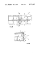
- FIG. 4 is a sectional view similar to that shown in FIG. 2, however, with the container illustrated in the closed position;
- FIG. 5 is a cross-sectional view of a part of the stop mechanism
- FIG. 6 is an elevational view of one of the parts of the stop mechanism illustrated in FIG. 5;
- FIG. 7 is a plan view of the part shown in FIG. 6;
- FIG. 8 is a front elevational view of the container showing the locking parts located on the side of the box-like part and of the hinged cover;
- FIG. 9 is a partial sectional view of the container taken along line IX--IX in FIG. 8 with the hinged cover in a partly open position moving toward the box-like part.
- FIG. 1 a storage container 40 is shown in a perspective view.
- the container 40 consists of a box-like part 1 and a hinged cover 3 connected to it and shown in the open position. Hinged cover 3 is secured by a pair of hinges 4, 4' shown schematically and spaced apart along the rear side wall of the container.
- the container 40 is rectangular in shape and its interior is divided by a number of wall portions 2', 2" extending transversely of one another into a plurality of compartments 2.
- Such a container having a partitioned interior is known and is generally characterized as a small storage container for holding an assortment of parts.
- Each of the hinges 4, 4' located on the rear wall 1" of the box-like part 1 has two bearing parts located on the hinged cover and another two located on the rear wall 1".
- a helical spring 23, 23' extends between the bearing parts and is held by a schematically shown bolt or pin 23 a , 23 b which extend through the bearing parts.
- Each helical spring has two spring arms, not further described, one of which rests on the box-like part 1 with the other bearing against the hinged cover 3 and the spring is stressed during the opening of the hinged cover.
- FIG. 1 displays a stop mechanism 15 which holds the hinged cover 3 in the open position and the stop mechanism is more fully described below.
- stop mechanism 15 is arranged within the container 40.
- the stop mechanism comprises a guide sleeve 11 secured to the bottom 1 a of the box-like part 1 and extending in the upward direction of the container.
- a stop pin 10 is axially slidably guided in the guide sleeve.
- the stop mechanism includes an elongated supporting lever 7 engaged, in the open position, at its front end with the stop pin 10 and its rear end is hinged to the cover 3. At its rear end, the supporting lever 7 is pivotally secured to a holding member 5 attached to the inside of the cover 3. The supporting lever 7 is held at the holding member 5 by a pin or bolt 6 which extends through the supporting lever and the holding member.
- a roller 8 is rotatably mounted on the front end of the supporting lever 7 and, in the illustrated closed position of FIG. 2, it is in contact with the stop pin 10.
- a pin or bolt 6' secures the roller 8 to the supporting lever.
- FIG. 3 there is a side view of the stop mechanism 15 when the cover is in the open position and with the stop mechanism in engagement with the box-like part 1 and the cover 3.
- Supporting lever 7 has a fork-shaped rear end pivoted to the holding member 5 secured on the cover 3. At its opposite or front end the supporting lever 7 is also fork-shaped and supports the roller 8 and is guided along the top of the wall portion 2' by the laterally extending angle shaped-section 9.
- guide sleeve 11 is shown having a base portion 11' secured within a recess 12 in the bottom 1 a of the box-like part 1.
- Stop pin 10 extends upwardly from the guide sleeve 11 and has a transversely extending projection 13 which serves as a stop.
- Guide sleeve 11 includes an upper portion 11" containing a groove 22 extending in the axial direction of the pin and the sleeve, and the groove is arranged to receive the projection 13.
- FIG. 4 the stop mechanism 15 is shown in the position it adopts when the container is closed and the stop mechanism is unstressed.
- the box-like part 1 is shown along with the hinged cover 3, the hinge 4 including hinge pin 23 a and the supporting lever 7 hinged to the inside of the cover with its angle-shaped section 9 resting on the top edge of the adjacent wall portion 2'.
- this particular wall portion 2' is somewhat lower than the remaining wall portions.
- the roller 8 is shown on the front end of the supporting lever.
- the guide sleeve 11 is attached to the bottom 1 a of the box-like part 1 and the lateral projection 13 on the stop pin 10 is located in the groove 22.
- An actuating member 18 is slidably mounted in the bottom of the guide sleeve 11 and extends downwardly below the bottom 1 a of the box-like part 1.
- FIG. 5 displays a section through the plane of symmetry of guide sleeve 11 with the stop pin 10 positioned within the sleeve so that it is slidable in the common axial direction of the pin and sleeve.
- Cap-shaped actuating member 18 is secured by a screw 17 to the bottom of the stop pin 10.
- the bottom portion 11' of the guide sleeve 11 forms a recess 19 around the pin 10.
- a compression spring 20 encircles the stop pin and is supported at its upper end against the surface 21 of the recess 19 and at its lower end against the inside surface 18' of the actuating member 18.
- the container is shown in the unstressed state in FIGS.
- the stop pin 10 which, for the most part, has a rounded outside surface, is shown in elevation and plan. Though for the most part its outside surface is rounded, the stop pin 10 has a flat elongated side 14 and its upper end has a recess 10' extending downwardly from the top for about half of the cross section of the pin. In other words, the recess extends laterally from a vertical plane coinciding with one side of the projection 8 to the outside surface of the pin.
- the vertical wall of the recess 10' serves in the open position of the hinge cover 3 as a contact surface for the roller 8 rotatably mounted on the front end of the supporting lever 7, note FIG. 2.
- stop pin 10 At its lower end, stop pin 10 has a tapped hole 17' into which the screw 17 can be threaded.
- guide sleeve 11 is formed integrally with the adjacent wall portion 2' and its upper portion 11" has a flattened surface 16 formed by the wall portion 2' with the lower portion 11' having a corresponding recess 2 a penetrating the all portion 2', which is shown only partially in FIG. 5.
- Stop pin 10 is guided in the sleeve 11 with its axially extending flat side 14 in contact with the wall portion 2' so that it is secured against rotation.
- FIG. 8 the storage container 40 is viewed looking at the front side of the box-like part 1 and of the hinged cover 3.
- a first locking part 25 is provided on the front face of the box-like part 1, that is, it is formed on the outside surface 1' of the front side.
- Locking part 25 has a recess 26 in which a first magnetic element 27 is secured by means, not shown.
- a stepped surface 28 is arranged around the outside of the box-like part 1, located above the first locking part 25, and serving, in the closed position of the container, as a support for the cover 3.
- another locking part 30 is arranged on the front face of the cover 3.
- locking part 30 is formed on the hinge cover and has a recess 31 in which a second magnetic element 32 is secured by means, not shown.
- a downwardly facing edge surface 33 extends around the interior of the cover 3 and in the closed position of the container 40, the edge surface 33 rests on the stepped surface 28 on the box-like part.
- FIG. 9 a portion of the storage container 40 is shown in section along the line IX--IX in FIG. 8 and the cover 3 is shown moving in the direction of the arrow 35 toward the closed position.
- locking part 30 includes the second magnetic element 32 within the recess 31 and the magnetic element includes the polarity segments N' and S'.
- the polarity segments N, S and N', S' of the magnetic segments 27, 32 are arranged relative to one another as viewed in the closing direction 35 so that initially the two unipolar segments N, N' are disposed opposite one another and then in the closed position and the polarity segments N,S' and S, N' are aligned opposite one another with the opposite segments having opposed polarity.
- Locking parts 25, 30 are preferably formed as integral parts of the box-like part 1 and the cover 3, respectively. In the closed position of the container 40 the magnetic elements overlap.
- two compartments 2 are shown defined by the bottom 1 a and separated in the vertical direction by wall portions 2', 2" extending transversely of one another.
- the magnetic elements 27, 32 positioned in the locking parts 25, 30 are commercially available permanent magnets of flat construction, known per se.
- the stop mechanism of the present invention operates in connection with the two working parts as follows:
- the storage container 40 rests on a base, not shown, such as a table or a workbench, with the cover 3 shown in the open position relative to the box-like part 1, and secured in this position by the supporting lever 7 hinged to the cover and in engagement with the stop mechanism 15.
- the actuation member 18 is shown extending downwardly from the bottom 1 a of the box-like part, however, when the box-like part rests on a support base the actuating member is pressed against the biasing force of spring 20 through the weight of the container into the recess 19 in the bottom sleeve, such as is displayed in FIGS. 2 and 3.
- the actuating member 18 and the stop pin 10 connected to it and guided within the guide sleeve 11 is pushed outwardly from the bottom 1 a of the box-like part 1 by the biasing force of the spring 20 in the direction opposite to the arrow A.
- the stop pin moves out of engagement with the roller 8 of the supporting lever 7 and simultaneously the cover 3 is returned toward the closed position by the biasing force of the helical springs 23, 23' on the hinges securing the cover to the box-like part.
- the stop mechanism 15 assumes the position illustrated in FIG. 4.
Landscapes
- Engineering & Computer Science (AREA)
- Mechanical Engineering (AREA)
- Closures For Containers (AREA)
Applications Claiming Priority (4)
| Application Number | Priority Date | Filing Date | Title |
|---|---|---|---|
| CH8920/80 | 1980-12-03 | ||
| CH892080 | 1980-12-03 | ||
| CH1123/81 | 1981-02-20 | ||
| CH112381 | 1981-02-20 |
Publications (1)
| Publication Number | Publication Date |
|---|---|
| US4375863A true US4375863A (en) | 1983-03-08 |
Family
ID=25686713
Family Applications (1)
| Application Number | Title | Priority Date | Filing Date |
|---|---|---|---|
| US06/323,356 Expired - Fee Related US4375863A (en) | 1980-12-03 | 1981-11-20 | Mechanism for automatically closing a storage container |
Country Status (2)
| Country | Link |
|---|---|
| US (1) | US4375863A (de) |
| EP (1) | EP0053577A1 (de) |
Cited By (15)
| Publication number | Priority date | Publication date | Assignee | Title |
|---|---|---|---|---|
| US4609122A (en) * | 1985-11-01 | 1986-09-02 | Ziegenbein Keith J | Automatic touch actuated door opener |
| US4723242A (en) * | 1986-06-27 | 1988-02-02 | Sperry Corporation | Digital adaptive voting |
| US4966203A (en) * | 1988-05-05 | 1990-10-30 | Lamiflex S.P.A. | Separator structure for guiding weaving loom harness frames |
| US5067625A (en) * | 1989-06-05 | 1991-11-26 | Nifco Inc. | Device for opening and closing lid |
| US5695098A (en) * | 1995-08-04 | 1997-12-09 | King; Scott Edward | Safety paint bucket |
| US5749730A (en) * | 1996-02-20 | 1998-05-12 | Jordco, Inc. | Dental organizer for light-sensitive materials |
| US6336567B1 (en) * | 1997-06-13 | 2002-01-08 | Kakizaki Manufacturing Co., Ltd. | Magnetic secured container closure with release by movement of magnetic member |
| US20020139804A1 (en) * | 2001-04-03 | 2002-10-03 | Lori Greiner | Decorative container |
| US20030160549A1 (en) * | 2002-01-10 | 2003-08-28 | Pietrantoni Dennis P. | Device for adjusting lid cover for oxygen mask dispensing container |
| US20040068820A1 (en) * | 2002-10-10 | 2004-04-15 | Jordco, Inc. | Porous material for insertion cleaning of instruments |
| US20050121015A1 (en) * | 2003-07-25 | 2005-06-09 | National Paintball Supply, Inc. | Secure closure system for paintball items |
| US20090181134A1 (en) * | 2008-01-10 | 2009-07-16 | Sallyann Hayden Lefevre | Keepsake cake kit |
| US20110229843A1 (en) * | 2010-03-17 | 2011-09-22 | Jordco, Inc. | Dental instrument servicing system |
| US9629701B2 (en) | 2011-08-31 | 2017-04-25 | Jordco, Inc. | Method and apparatus for cleaning and storing endodontic tools |
| US20190140437A1 (en) * | 2017-11-06 | 2019-05-09 | Primex Manufacturing Ltd. | Networking enclosure assembly with magnetic algnment and interlocking, adaptable to be installed in different locations and positions |
Families Citing this family (1)
| Publication number | Priority date | Publication date | Assignee | Title |
|---|---|---|---|---|
| US5681743A (en) * | 1995-07-20 | 1997-10-28 | Becton Dickinson And Company | Plate assembly useful for microbiological laboratory procedures |
Citations (2)
| Publication number | Priority date | Publication date | Assignee | Title |
|---|---|---|---|---|
| US2850200A (en) * | 1954-07-21 | 1958-09-02 | Hofmann Ulrich | Hinged lid construction |
| US3093258A (en) * | 1960-06-09 | 1963-06-11 | Oswald W Turner | Cover lift |
Family Cites Families (2)
| Publication number | Priority date | Publication date | Assignee | Title |
|---|---|---|---|---|
| CH230392A (de) * | 1941-12-12 | 1943-12-31 | Blohm & Voss Fa | Behälter zum Aufbewahren von Gegenständen, wie Nieten, Schrauben, Splinte. |
| CH530912A (de) * | 1970-10-02 | 1972-11-30 | Utz Ag Georg | Transportbehälter mit anscharniertem Deckel |
-
1981
- 1981-04-07 EP EP81810135A patent/EP0053577A1/de not_active Withdrawn
- 1981-11-20 US US06/323,356 patent/US4375863A/en not_active Expired - Fee Related
Patent Citations (2)
| Publication number | Priority date | Publication date | Assignee | Title |
|---|---|---|---|---|
| US2850200A (en) * | 1954-07-21 | 1958-09-02 | Hofmann Ulrich | Hinged lid construction |
| US3093258A (en) * | 1960-06-09 | 1963-06-11 | Oswald W Turner | Cover lift |
Cited By (24)
| Publication number | Priority date | Publication date | Assignee | Title |
|---|---|---|---|---|
| US4609122A (en) * | 1985-11-01 | 1986-09-02 | Ziegenbein Keith J | Automatic touch actuated door opener |
| US4729490A (en) * | 1985-11-01 | 1988-03-08 | Ziegenbein Keith J | Automatic touch actuated door opener |
| US4723242A (en) * | 1986-06-27 | 1988-02-02 | Sperry Corporation | Digital adaptive voting |
| US4966203A (en) * | 1988-05-05 | 1990-10-30 | Lamiflex S.P.A. | Separator structure for guiding weaving loom harness frames |
| US5067625A (en) * | 1989-06-05 | 1991-11-26 | Nifco Inc. | Device for opening and closing lid |
| US5695098A (en) * | 1995-08-04 | 1997-12-09 | King; Scott Edward | Safety paint bucket |
| US5749730A (en) * | 1996-02-20 | 1998-05-12 | Jordco, Inc. | Dental organizer for light-sensitive materials |
| US6336567B1 (en) * | 1997-06-13 | 2002-01-08 | Kakizaki Manufacturing Co., Ltd. | Magnetic secured container closure with release by movement of magnetic member |
| US20020139804A1 (en) * | 2001-04-03 | 2002-10-03 | Lori Greiner | Decorative container |
| US7296572B2 (en) * | 2002-01-10 | 2007-11-20 | Avox Systems Inc. | Device for adjusting lid cover for oxygen mask dispensing container |
| US20030160549A1 (en) * | 2002-01-10 | 2003-08-28 | Pietrantoni Dennis P. | Device for adjusting lid cover for oxygen mask dispensing container |
| US20080066760A1 (en) * | 2002-01-10 | 2008-03-20 | Pietrantoni Dennis P | Device For Adjusting Lid Cover For Oxygen Mask Dispensing Container |
| US9066776B2 (en) | 2002-10-10 | 2015-06-30 | Jordco, Inc. | Porous material for insertion cleaning of instruments |
| US8231734B2 (en) | 2002-10-10 | 2012-07-31 | Jordco, Inc. | Porous material for insertion cleaning of instruments |
| US8635735B2 (en) | 2002-10-10 | 2014-01-28 | Jordco, Inc. | Porous material for insertion cleaning of instruments |
| US20040068820A1 (en) * | 2002-10-10 | 2004-04-15 | Jordco, Inc. | Porous material for insertion cleaning of instruments |
| US20050121015A1 (en) * | 2003-07-25 | 2005-06-09 | National Paintball Supply, Inc. | Secure closure system for paintball items |
| US20080087264A1 (en) * | 2003-07-25 | 2008-04-17 | Kee Action Sports I Llc | Secure closure system for paintball items |
| US20090181134A1 (en) * | 2008-01-10 | 2009-07-16 | Sallyann Hayden Lefevre | Keepsake cake kit |
| US20110229843A1 (en) * | 2010-03-17 | 2011-09-22 | Jordco, Inc. | Dental instrument servicing system |
| US9474584B2 (en) | 2010-03-17 | 2016-10-25 | Jordco, Inc. | Dental instrument servicing system |
| US9629701B2 (en) | 2011-08-31 | 2017-04-25 | Jordco, Inc. | Method and apparatus for cleaning and storing endodontic tools |
| US20190140437A1 (en) * | 2017-11-06 | 2019-05-09 | Primex Manufacturing Ltd. | Networking enclosure assembly with magnetic algnment and interlocking, adaptable to be installed in different locations and positions |
| US11114830B2 (en) * | 2017-11-06 | 2021-09-07 | Primex Manufacturing Ltd. | Networking enclosure assembly with magnetic alignment and interlocking, adaptable to be installed in different locations and positions |
Also Published As
| Publication number | Publication date |
|---|---|
| EP0053577A1 (de) | 1982-06-09 |
Similar Documents
| Publication | Publication Date | Title |
|---|---|---|
| US4375863A (en) | Mechanism for automatically closing a storage container | |
| US4032037A (en) | Closure and fastener for trash bins | |
| US2725274A (en) | Portable bar | |
| US4498583A (en) | Diskette storage container for storing a large quantity of diskettes | |
| EP3807167A1 (de) | Gruppenschliessfach mit versenkter tür zur herstellung eines schlanken profils | |
| KR860009364A (ko) | 동전 자동 수납장치와 동전 수납상자 | |
| JPH0728381Y2 (ja) | 扉開閉機構 | |
| US4749098A (en) | File card container | |
| US2604260A (en) | Mailbox | |
| US3061871A (en) | Torsion bar hinge structure | |
| US3640451A (en) | Receptacle device | |
| ES256663U (es) | Dispositivo para inmovilizar en posicion de apertura parcialy-o total una tapa sobre la cuba de un contenedor | |
| US3215262A (en) | Lock | |
| JPH03170107A (ja) | 蓋付き引出し装置 | |
| US2569117A (en) | Combined stand and cabinet apparatus for books | |
| US2625293A (en) | Hinged lid actuator and prop | |
| KR0125603Y1 (ko) | 냉장고 도어의 고정장치 | |
| KR19990026868U (ko) | 자동차의 콘솔박스 덮개 개폐장치 | |
| US3094236A (en) | Latch mechanism | |
| JPH0617985Y2 (ja) | 巻き戸の取付け構造 | |
| JPS6297505A (ja) | 吊戸棚 | |
| US1340034A (en) | File-box | |
| SU1557308A1 (ru) | Устройство запорное дл много щичного шкафа | |
| JPH0716599Y2 (ja) | 保管容器 | |
| GB1564306A (en) | Storage cabinet |
Legal Events
| Date | Code | Title | Description |
|---|---|---|---|
| FEPP | Fee payment procedure |
Free format text: MAINTENANCE FEE REMINDER MAILED (ORIGINAL EVENT CODE: REM.); ENTITY STATUS OF PATENT OWNER: SMALL ENTITY |
|
| LAPS | Lapse for failure to pay maintenance fees | ||
| STCH | Information on status: patent discontinuation |
Free format text: PATENT EXPIRED DUE TO NONPAYMENT OF MAINTENANCE FEES UNDER 37 CFR 1.362 |
|
| FP | Lapsed due to failure to pay maintenance fee |
Effective date: 19870308 |