US4391045A - Drawing instrument or apparatus - Google Patents
Drawing instrument or apparatus Download PDFInfo
- Publication number
- US4391045A US4391045A US06/244,506 US24450681A US4391045A US 4391045 A US4391045 A US 4391045A US 24450681 A US24450681 A US 24450681A US 4391045 A US4391045 A US 4391045A
- Authority
- US
- United States
- Prior art keywords
- lobes
- disc
- shaped
- lobe
- frame
- Prior art date
- Legal status (The legal status is an assumption and is not a legal conclusion. Google has not performed a legal analysis and makes no representation as to the accuracy of the status listed.)
- Expired - Lifetime
Links
Images


Classifications
-
- B—PERFORMING OPERATIONS; TRANSPORTING
- B43—WRITING OR DRAWING IMPLEMENTS; BUREAU ACCESSORIES
- B43L—ARTICLES FOR WRITING OR DRAWING UPON; WRITING OR DRAWING AIDS; ACCESSORIES FOR WRITING OR DRAWING
- B43L11/00—Non-circular-curve-drawing instruments
- B43L11/08—Non-circular-curve-drawing instruments for drawing involutes
-
- B—PERFORMING OPERATIONS; TRANSPORTING
- B43—WRITING OR DRAWING IMPLEMENTS; BUREAU ACCESSORIES
- B43L—ARTICLES FOR WRITING OR DRAWING UPON; WRITING OR DRAWING AIDS; ACCESSORIES FOR WRITING OR DRAWING
- B43L13/00—Drawing instruments, or writing or drawing appliances or accessories not otherwise provided for
- B43L13/20—Curve rulers or templets
- B43L13/201—Stencils for drawing figures, objects
Definitions
- the invention relates to drawing instruments or apparatus, and more specifically to drawing instruments intended primarily, but not exclusively for use as a toy by children in the creation of decorative patterns and designs of a varying nature.
- the invention is equally useful to artists, designers and similar professional persons.
- One well known drawing instrument involves the use of a toothed ring primary member and a toothed disc secondary member, both ring and disc each having a plurality of holes through which may be projected a pen, pencil or the like, so that the ring and disc may be moved relative to each other by the pen, pencil or the like, with the teeth of the primary and secondary members in mesh, and simultaneously produce a design on a surface supporting the drawing instrument.
- My U.S. Pat. No. Re. 26,341--Instruments or Apparatus discloses an instrument being marketed as Spirograph® Design Drawing Toy.
- the holes in the Spirograph® drawing instrument include round holes, of sufficient diameter only to accommodate the tip or writing point of a pen, pencil or the like, so that a design produced on the surface supporting the instrument when the pen, pencil or the like is engaged in a hole and is moved to cause relative movement between the two members, results only from such relative movement, the design produced not being dependent upon the shape of the hole.
- the present invention seeks to provide an improved form of drawing instrument or apparatus which does not suffer the disadvantages and limitations of the above-described apparatus, and accordingly the invention provides a drawing instrument in the form of a self-indexing stencil comprising a conjugated cam system consisting of a first member having a multi-lobed cam-shaped surface, and a second member having a multi-lobed cam-shaped surface, said first member having one or more shaped apertures therein, whereby when an, or the, aperture shape in said first member is completely traced out by a pen, pencil or the like, engaging the surface of the aperture, said first member is indexed one part of one revolution relative to said second member, said one part being dependent upon the number of lobes on said cam-shaped surfaces, said pen, pencil or the like simultaneously drawing or inscribing a design upon a surface supporting the drawing instrument.
- said first member will be a disc having a multi-lobed cam-shaped external surface
- said second member will be a frame having a multi-lobed cam-shaped internal surface
- the size of the disc relative to the internal surface of the frame will be such that the mating surfaces will always be in engagement with each other.
- the number of lobes on the external cam-shaped surface of the disc will be one less than the number of lobes on the internal cam-shaped surface of the frame, the pitch and size of the lobes being dependent upon the amount of relative indexing required when a, or the, shaped aperture is completely traced out by a pen, pencil or the like.
- the apparatus will include one conjugated cam system consisting of one first member in the form of a disc having a multi-lobed cam-shaped external surface, and one or more apertures therein, and one second member in the form of a frame having a multi-lobed cam-shaped internal surface.
- the said second member will preferably be constituted by two opposed plate-like members between which is located the first member, the plate-like members having opposed openings so as to afford access to the first member and being secured together so as to maintain the multi-lobed cam-shaped surfaces in mesh, the first member being movable relative to and between the said plate-like members.
- the first member will preferably be transparent or translucent so that the design produced can be viewed through the first member.
- the drawing instrument will consist of a plurality of conjugated cam systems each including a multi-lobed cam-shaped external surface and a multi-lobed cam-shaped internal surface.
- the multi-lobed cam-shaped external surfaces will be located on first members of the conjugated cam systems, said first members each being in the form of a disc having a plurality of shaped apertures.
- the plurality of conjugated cam systems will preferably be five.
- the plurality of conjugated cam systems will preferably be constituted by a plurality of first members each having a muli-lobed cam-shaped external surface and a common second member having a corresponding plurality of multi-lobed cam-shaped internal surfaces, said second member being constituted by opposed plate-like members having a corresponding plurality of openings so as to afford access to said first members.
- the first and second members will be composed of synthetic plastic material, the first members preferably being transparent or translucent.
- the outer planar surface of at least one of the plate-like members may be provided with a coating of one or more areas of a friction material such as rubber or similar material so as to prevent sliding of the apparatus on the supporting surface.
- FIG. 1 is a top plan view of a drawing instrument or apparatus according to the invention, which illustrates the apparatus in its simplest form;
- FIG. 2 is a cross-sectional view taken along line 2--2 of FIG. 1;
- FIGS. 3 and 4 show a design produced when a writing or drawing instrument such as a pen, pencil or the like, is used in certain of the apertures shown in FIG. 1;
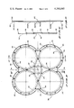
- FIG. 5 is a top plan view of a component of the drawing instrument in its preferred form
- FIG. 6 is a cross-sectional view taken along line 6--6 of FIG. 5;
- FIG. 7 is a cross-sectional view of the drawing instrument as taken along line 7--7 of FIG. 5;
- FIG. 8 is a top plan view of another component of the drawing instrument in its preferred form;
- FIG. 9 is a cross-sectional view taken line 9--9 of FIG. 8;
- FIG. 10 is a side view as taken along line 10--10 of FIG. 8;
- FIG. 11 is a top plan view of additional components of the drawing instrument in its preferred form
- FIG. 12 is a cross-sectional view taken along line 12--12 of FIG. 11;
- FIG. 13 is a cross-sectional view as taken along line 13--13 of FIG. 11;
- FIG. 14 is a top plan view of all the assembled components shown in FIGS. 5 to 13;
- FIG. 15 is a cross-sectional view as taken along line 15--15 of FIG. 14;
- FIG. 16 is a cross-sectional view as taken along line 16--16 of FIG. 14;
- FIGS. 17 and 18 show examples of designs produced by operation of the assembled instrument of FIG. 14.
- the drawing instrument shown includes a first member in the form of a disc 2 having a surface or edge 2A, and a second member in the form of a frame designated generally by reference numeral 4.
- the frame 4 is formed from opposed rectangularly-shaped plate-like members 6 and 8; the plate-like members 6 and 8 together defining a recess 10 therebetween in which is located the disc 2, the disc 2 being held captive, but movable, within the recess 10.
- Each plate-like member 6 and 8 has a circular opening therein, said openings being referenced by numerals 6A and 8A respectively.
- the surface or edge 10A of the recess 10 is a multi-lobed cam-shaped surface.
- the external surface or edge 2A of the disc 2 is also a multi-lobed cam-shaped surface; said two surfaces co-acting with one another, to form a conjugated cam system.
- the number of lobes on the cam-shaped surface 2A is one less than the number of lobes on the cam-shaped surface 10A, so that point contact of the cam surfaces is possible on all lobes, these points of contact being indicated by reference numeral 12. Such multiple contact ensures that the disc 2 cannot get out of "mesh", or wedge in a locked position with the surface 10A of the recess 10.
- the plate-like members (also referred to herein as plates) 6 and 8 are preferably, but not necessarily, formed of an opaque plastic material, and the disc 2 is preferably formed of a transparent or translucent plastic material.
- the lower surface of the plate 8 is covered with a thin film layer 14 of rubber, or other friction material, so that the writing instrument can be held stationary with ease, to prevent slipping with respect to surface 16 which supports the instrument, said surface 16, for example, being a sheet of paper.
- the layer 14 obviates the need for fastening pins or the like.
- the disc 2 is provided with downwardly extending dome-shaped elements or protrusions 30 which bear upon the base member 8.
- the disc 2 has a plurality of stencil-shaped apertures or openings 18, 20, 22, 24, and 26, which are capable of receiving the tip 28A of a hand-held writing instrument 28 such as a pen, pencil or the like, which projects through the opening 8A of the plate-like member 8 so as to be in contact with the supporting surface 16.
- the writing instrument 28 serves to move the disc 2 relative to the frame 4, and simultaneously draws or inscribes a design upon the supporting surface 16. The movement of the disc 2 and the simultaneous production of a design on the supporting surface is achieved as follows.
- the slight pressure of the tip 28A of the writing instrument 28 acting inside the stencil-shaped aperture produces contact between the surface or edge 2A of the disc 2, and the surface or edge 10A of the recess 10, at a point in line with the direction of this pressure, this line being at a right angle to the shape of the stencil-shaped aperture, at the point being touched by the tip 28A of the writing instrument 28.
- this line of pressure will have turned through one complete turn.
- the lobes of the cam-shaped surface 2A of the disc 2 will have been progressively pushed into the matching lobes of the cam-shaped surface 10A, and the disc 2 will have turned through 360 degrees divided by the number of lobes on the cam-shaped surface 10A.
- the disc 2 is automatically indexed, as the writing instrument 28 is moved around the surface of the stencil-shaped aperture. After the writing instrument 28 has been moved around the surface of the stencil-shaped aperture by as many times as there are lobes on the cam-shaped surface 10A, the writing instrument and the disc 2 will have returned to the original starting points relative to the frame 4 and the surface 16 on which the design is being produced; at this point, the design will be finished.
- the shape of the stencil-shaped aperture 18 has been computed to produce the finished design shown in FIG. 3, which consists of twelve circles surrounding a larger circle. In this particular case a slight deformation of the smaller circles of the design is theoretically inevitable, but this could be avoided by increasing the diameter of these circles to a calculable value.
- FIG. 4 A further example of a finished design is shown in FIG. 4, which is produced by the stencil-shaped aperture 20 of the disc 2.
- the movement of the disc 2 by the tip 28A of the writing instrument 28 relative to the frame 4 will, it should be appreciated, be in the opposite sense to the manner in which the writing instrument 28 is being moved, i.e., when the writing instrument 28 is moved in a clockwise direction, the disc 2 will be moved in a counter-clockwise direction and vice versa.
- FIGS. 5 to 16 of the drawings Having described the basic construction and principles of operation, of a drawing instrument according to the invention, a preferred embodiment of the invention will now be described with specific reference to FIGS. 5 to 16 of the drawings.
- FIGS 5 to 10 disclose a frame equivalent to the frame 4 of FIGS. 1 and 2.
- the frame is comprised of a plate-like member 32 (FIGS. 5 to 7) and a plate-like base member 60 (FIGS. 8 to 10); the complete frame being shown in FIGS. 14 to 16.
- the plate member 32 of FIGS. 5 to 7 is formed from a shaped plate-like member having a plurality of multi-lobed cam-shaped surfaces 34, 36, 38, and 40, which are spaced equidistantly from a theoretical center point 42 of the plate member, and located about respective openings 44, 46, 48, and 50 of the plate member.
- a multi-lobed cam-shaped surface 52 is provided, which is located symmetrically about the theoretical axis 42, and it includes an opening 54 at the center of the plate member 32.
- the cam-shaped surface 52 and the opening 54 are equi-spaced from the cam-shaped surfaces 34, 36, 38, and 40, and from the openings 44, 46, 48 and 50.
- the cam-shaped surfaces are raised from the planar surface of the member 32.
- the plate member 32 is preferably formed of an opaque plastic material, it has a plurality of recessed bosses 56, and its peripherry is flanged as indicated by reference numerals 58.
- the plate-like base member 60 consists of a shaped plate--which shape corresponds to the shape of the plate member 32--having four openings 62, 64, 66 and 68 spaced equidistantly from a theoretical center point 70 of the plate, and an opening 72 located symmetrically about said center point 70 and equi-spaced from the four openings 62, 64, 66 and 68.
- the base plate 60 further has a plurality of protruding pegs 74, the positioning of the pegs 74 corresponding to the positions of the recessed bosses 56 of the plate member 32, and the positions of the openings 62, 64, 66, 68, and 72 corresponding to the positions of the openings 44, 46 , 48, 50 and 54 in the plate member 32, so that said openings are in register when the apparatus is assembled with the pegs 74 located in and gripped by the recessed bosses 56.
- the outer planar surface of the base member 60 will preferably have a coating or film layer of rubber or other friction material similar to that shown and described in conjunction with FIG. 2
- the base member 60 is preferably formed of an opaque plastic material, similar to that of the plate member 32.
- the overall dimension of the base member 60 is slightly smaller than the overall dimension of the plate member 32, such that the base member 60 may fit within the flange 58 of the plate member 32, when the apparatus is in assembled condition.
- FIGS. 11 to 13 show a plurality of discs for location between, and cooperation with the members 32 and 60 of the frame, i.e., within a recess formed by the members 32 and 60.
- Each of the discs 76, 78, 80, 82 and 84 has a multi-lobed cam-shaped surface 76A, 78A, 80A, 82A and 84A respectively, the number of lobes on these cam-shaped surfaces being one less than the number of lobes on their co-acting cam-shaped surfaces 34, 36, 38, 40 and 52 of the frame.
- the number of lobes on the cam-shaped surfaces 76A, 78A, 80A and 82A are equal, but it will be appreciated that the number of lobes on these surfaces could differ, provided that the number of lobes on their respective co-acting cam-shaped surfaces 34, 36, 38 and 40, differed accordingly.
- Each disc has a plurality of shaped stencil-like apertures or openings, and each disc has a plurality of generally dome-shaped elements or protrusions 76B, 78B, 80B, 82B, and 84B respectively, to prevent flat-plate adhesion as previously referred to.
- the discs are preferably formed of a transparent or translucent plastic material.
- FIGS. 14 to 16 show the components of FIGS. 5 to 13 in their assembled condition.
- the plate-like base member 60 is located within the flange 58 of the plate member 32 with the discs 76, 68, 80, 82 and 84 located in the recess between the members 32 and 60, the plate members 32 and 60 being secured together so as to retain the discs in position by interaction between the recessed bosses 56 and the protruding pegs 74.
- the multi-lobed cam-shaped surfaces of the discs and frame are in interengagement and cannot come out of this engagement due to the discs being sandwiched between the members 32 and 60. If preferred, or course, the instrument could be constructed so that the discs could be removed and interchanged.
- the stencil-shaped apertures or openings in any one of the discs are computed so that a composite design can be drawn using several of the shaped apertures which are compatible with each other. Such a composite design is shown in FIG. 17.
- the design produced on the surface supporting the drawing apparatus is a combination of the shape of the aperture in the disc and the movement of the disc relative to the frame.
- Drawing apparatus according to the invention has the simplicity of use of a conventional stencil, but has the advantages firstly that the stencil moves automatically as the pen, pencil or the like, is moved by hand in the shaped aperture, and secondly that of producing accurate and intricate designs of interest and appeal.
- the provision of the thin film of rubber or other friction material enables the drawing apparatus to be used without the need for fastening pins or the like, which is an advantage when the apparatus is to be used by young children.
- the self-contained design and construction of the apparatus ensures that parts cannot be lost or misplaced, as can happen with other forms of drawing apparatus.
- the multi-lobed cam-shaped surface(s) of the frame might be formed on separate ring-shaped members which could be inserted into recessed areas in the plate-like members of the frame, so that the ring-shaped members would be immovable relative to the frame.
- the multi-lobed cam-shaped surfaces(s) of the frame could be formed by two mating plates, these plates being identical and each incorporating one-half of the cam-shaped surfaces.
Landscapes
- Toys (AREA)
- Manufacture Or Reproduction Of Printing Formes (AREA)
- Input Circuits Of Receivers And Coupling Of Receivers And Audio Equipment (AREA)
- Telephone Function (AREA)
- Materials For Medical Uses (AREA)
- Mechanical Pencils And Projecting And Retracting Systems Therefor, And Multi-System Writing Instruments (AREA)
Applications Claiming Priority (4)
| Application Number | Priority Date | Filing Date | Title |
|---|---|---|---|
| GB8009084 | 1980-03-18 | ||
| GB8009084 | 1980-03-18 | ||
| GB8029079 | 1980-09-09 | ||
| GB8029079 | 1980-09-19 |
Publications (1)
| Publication Number | Publication Date |
|---|---|
| US4391045A true US4391045A (en) | 1983-07-05 |
Family
ID=26274864
Family Applications (1)
| Application Number | Title | Priority Date | Filing Date |
|---|---|---|---|
| US06/244,506 Expired - Lifetime US4391045A (en) | 1980-03-18 | 1981-03-16 | Drawing instrument or apparatus |
Country Status (12)
| Country | Link |
|---|---|
| US (1) | US4391045A (fr) |
| EP (1) | EP0036732B1 (fr) |
| JP (1) | JPS6034493U (fr) |
| AU (1) | AU538162B2 (fr) |
| BR (1) | BR8101610A (fr) |
| CA (1) | CA1174042A (fr) |
| DE (1) | DE3162729D1 (fr) |
| DK (1) | DK117981A (fr) |
| ES (1) | ES500434A0 (fr) |
| FI (1) | FI810825A7 (fr) |
| NO (1) | NO810904L (fr) |
| NZ (1) | NZ196560A (fr) |
Cited By (6)
| Publication number | Priority date | Publication date | Assignee | Title |
|---|---|---|---|---|
| US5331744A (en) * | 1993-05-12 | 1994-07-26 | Bandai America Incorporated | Marker apparatus |
| FR2893534A1 (fr) * | 2005-11-21 | 2007-05-25 | Heller Sa Sa | Instrument de dessin pour la realisation de mandalas |
| WO2011047678A1 (fr) | 2009-10-19 | 2011-04-28 | Østberg Design Aps | Dispositif de dessin pour la création de mandalas |
| US20160243881A1 (en) * | 2015-02-24 | 2016-08-25 | Trends International, Llc | Drawing apparatus and method of use |
| US20220219484A1 (en) * | 2019-06-11 | 2022-07-14 | Yaaqov Israel BEN-DAVID | A fractal-based mandala drawing toolset |
| RU2826101C1 (ru) * | 2023-11-22 | 2024-09-03 | Варвара Сергеевна Загитова | Спирограф |
Families Citing this family (3)
| Publication number | Priority date | Publication date | Assignee | Title |
|---|---|---|---|---|
| GB2148201B (en) * | 1983-10-05 | 1987-09-03 | James Campbell Cramb | Drawing apparatus |
| GB201620901D0 (en) * | 2016-12-08 | 2017-01-25 | John Adams Leisure Ltd | Improvements to toy apparatus and method of assembly of the same |
| CN115008930B (zh) * | 2022-06-28 | 2023-06-02 | 中国地质大学(北京) | 一种戒指及手镯手绘设计模板尺 |
Citations (7)
| Publication number | Priority date | Publication date | Assignee | Title |
|---|---|---|---|---|
| US1349455A (en) * | 1920-03-25 | 1920-08-10 | Zeiner-Henriksen Hans Thorvald | Adjustable compass-dial |
| US2190071A (en) * | 1937-06-19 | 1940-02-13 | William M Keppers | Calculating protractor |
| FR1409907A (fr) * | 1964-07-23 | 1965-09-03 | Instrument de dessin servant à la confection de motifs géométriques | |
| US3230624A (en) * | 1963-07-25 | 1966-01-25 | Fisher Denys | Designs instruments or apparatus |
| FR1470756A (fr) * | 1965-03-05 | 1967-02-24 | Appareil pour le dessin de figures décoratives | |
| US3465445A (en) * | 1967-03-03 | 1969-09-09 | Denys Fisher Group Ltd | Drawing and design apparatus or instrument |
| US3900956A (en) * | 1972-04-15 | 1975-08-26 | Gakken Co Ltd | Apparatus for drawing composite pictorial patterns |
Family Cites Families (1)
| Publication number | Priority date | Publication date | Assignee | Title |
|---|---|---|---|---|
| US3568327A (en) * | 1967-11-10 | 1971-03-09 | Gakken Co Ltd | Apparatus for drawing composite pictorial patterns |
-
1981
- 1981-03-16 US US06/244,506 patent/US4391045A/en not_active Expired - Lifetime
- 1981-03-16 DK DK117981A patent/DK117981A/da not_active Application Discontinuation
- 1981-03-16 EP EP81301083A patent/EP0036732B1/fr not_active Expired
- 1981-03-16 DE DE8181301083T patent/DE3162729D1/de not_active Expired
- 1981-03-17 NO NO810904A patent/NO810904L/no unknown
- 1981-03-17 ES ES500434A patent/ES500434A0/es active Granted
- 1981-03-17 AU AU68459/81A patent/AU538162B2/en not_active Ceased
- 1981-03-17 CA CA000373137A patent/CA1174042A/fr not_active Expired
- 1981-03-17 FI FI810825A patent/FI810825A7/fi not_active Application Discontinuation
- 1981-03-18 BR BR8101610A patent/BR8101610A/pt unknown
- 1981-03-18 NZ NZ196560A patent/NZ196560A/xx unknown
-
1984
- 1984-06-30 JP JP1984099977U patent/JPS6034493U/ja active Pending
Patent Citations (7)
| Publication number | Priority date | Publication date | Assignee | Title |
|---|---|---|---|---|
| US1349455A (en) * | 1920-03-25 | 1920-08-10 | Zeiner-Henriksen Hans Thorvald | Adjustable compass-dial |
| US2190071A (en) * | 1937-06-19 | 1940-02-13 | William M Keppers | Calculating protractor |
| US3230624A (en) * | 1963-07-25 | 1966-01-25 | Fisher Denys | Designs instruments or apparatus |
| FR1409907A (fr) * | 1964-07-23 | 1965-09-03 | Instrument de dessin servant à la confection de motifs géométriques | |
| FR1470756A (fr) * | 1965-03-05 | 1967-02-24 | Appareil pour le dessin de figures décoratives | |
| US3465445A (en) * | 1967-03-03 | 1969-09-09 | Denys Fisher Group Ltd | Drawing and design apparatus or instrument |
| US3900956A (en) * | 1972-04-15 | 1975-08-26 | Gakken Co Ltd | Apparatus for drawing composite pictorial patterns |
Cited By (10)
| Publication number | Priority date | Publication date | Assignee | Title |
|---|---|---|---|---|
| US5331744A (en) * | 1993-05-12 | 1994-07-26 | Bandai America Incorporated | Marker apparatus |
| FR2893534A1 (fr) * | 2005-11-21 | 2007-05-25 | Heller Sa Sa | Instrument de dessin pour la realisation de mandalas |
| WO2011047678A1 (fr) | 2009-10-19 | 2011-04-28 | Østberg Design Aps | Dispositif de dessin pour la création de mandalas |
| US8458918B2 (en) | 2009-10-19 | 2013-06-11 | Ostberg Design Aps | Drawing device for creating mandala |
| US20160243881A1 (en) * | 2015-02-24 | 2016-08-25 | Trends International, Llc | Drawing apparatus and method of use |
| US10071592B2 (en) * | 2015-02-24 | 2018-09-11 | Spencer L Brinkerhoff, III | Drawing apparatus and method of use |
| US20220219484A1 (en) * | 2019-06-11 | 2022-07-14 | Yaaqov Israel BEN-DAVID | A fractal-based mandala drawing toolset |
| US11787224B2 (en) * | 2019-06-11 | 2023-10-17 | Yaaqov Israel BEN-DAVID | Fractal-based mandala drawing toolset |
| RU2826101C1 (ru) * | 2023-11-22 | 2024-09-03 | Варвара Сергеевна Загитова | Спирограф |
| RU2836751C1 (ru) * | 2024-09-04 | 2025-03-21 | Варвара Сергеевна Загитова | Спирограф |
Also Published As
| Publication number | Publication date |
|---|---|
| FI810825L (fi) | 1981-09-19 |
| NO810904L (no) | 1981-09-21 |
| AU6845981A (en) | 1981-09-24 |
| ES8204665A1 (es) | 1982-05-01 |
| DE3162729D1 (en) | 1984-04-26 |
| AU538162B2 (en) | 1984-08-02 |
| BR8101610A (pt) | 1982-10-26 |
| NZ196560A (en) | 1983-09-30 |
| EP0036732A1 (fr) | 1981-09-30 |
| ES500434A0 (es) | 1982-05-01 |
| CA1174042A (fr) | 1984-09-11 |
| JPS6034493U (ja) | 1985-03-09 |
| DK117981A (da) | 1981-09-19 |
| EP0036732B1 (fr) | 1984-03-21 |
| FI810825A7 (fi) | 1981-09-19 |
Similar Documents
| Publication | Publication Date | Title |
|---|---|---|
| US3465445A (en) | Drawing and design apparatus or instrument | |
| US4391045A (en) | Drawing instrument or apparatus | |
| USD249858S (en) | Table | |
| US4958454A (en) | Data recorder | |
| US4736526A (en) | Geometry template | |
| USD262485S (en) | Lavatory | |
| US10864766B2 (en) | Spiral art device | |
| US7055259B2 (en) | Template set for drawing three-dimensional shapes | |
| USD254695S (en) | Lantern housing | |
| US5390418A (en) | Tool for drawing circumferences | |
| US3061946A (en) | Drawing appliance for producing ornamental designs | |
| US4330955A (en) | Point of purchase display device | |
| US2602228A (en) | Protractor | |
| US2545131A (en) | Gear toy | |
| US1262971A (en) | Lettering-triangle. | |
| US3673712A (en) | Educational device | |
| USD265322S (en) | Educational electronic analog computer laboratory | |
| JPS62201785U (fr) | ||
| CN2167859Y (zh) | 幼儿计算绘画板 | |
| US3453738A (en) | Circle divider | |
| USD245807S (en) | Toy whistle | |
| JPS58184Y2 (ja) | 算数教習具 | |
| JPH0248390U (fr) | ||
| US5040986A (en) | Educational device for teaching handwriting skills | |
| JPH0444395Y2 (fr) |
Legal Events
| Date | Code | Title | Description |
|---|---|---|---|
| STCF | Information on status: patent grant |
Free format text: PATENTED CASE |
|
| MAFP | Maintenance fee payment |
Free format text: PAYMENT OF MAINTENANCE FEE, 4TH YEAR, PL 96-517 (ORIGINAL EVENT CODE: M170); ENTITY STATUS OF PATENT OWNER: LARGE ENTITY Year of fee payment: 4 |
|
| MAFP | Maintenance fee payment |
Free format text: PAYMENT OF MAINTENANCE FEE, 8TH YEAR, PL 96-517 (ORIGINAL EVENT CODE: M171); ENTITY STATUS OF PATENT OWNER: LARGE ENTITY Year of fee payment: 8 |
|
| MAFP | Maintenance fee payment |
Free format text: PAYMENT OF MAINTENANCE FEE, 12TH YEAR, LARGE ENTITY (ORIGINAL EVENT CODE: M185); ENTITY STATUS OF PATENT OWNER: LARGE ENTITY Year of fee payment: 12 |