US4424474A - Method and circuit arrangement for controlling the r.p.m. of a three-phase motor - Google Patents
Method and circuit arrangement for controlling the r.p.m. of a three-phase motor Download PDFInfo
- Publication number
- US4424474A US4424474A US06/326,907 US32690781A US4424474A US 4424474 A US4424474 A US 4424474A US 32690781 A US32690781 A US 32690781A US 4424474 A US4424474 A US 4424474A
- Authority
- US
- United States
- Prior art keywords
- circuit
- controlling
- circuit arrangement
- motor
- motor windings
- Prior art date
- Legal status (The legal status is an assumption and is not a legal conclusion. Google has not performed a legal analysis and makes no representation as to the accuracy of the status listed.)
- Expired - Fee Related
Links
Images



Classifications
-
- H—ELECTRICITY
- H02—GENERATION; CONVERSION OR DISTRIBUTION OF ELECTRIC POWER
- H02P—CONTROL OR REGULATION OF ELECTRIC MOTORS, ELECTRIC GENERATORS OR DYNAMO-ELECTRIC CONVERTERS; CONTROLLING TRANSFORMERS, REACTORS OR CHOKE COILS
- H02P27/00—Arrangements or methods for the control of AC motors characterised by the kind of supply voltage
- H02P27/02—Arrangements or methods for the control of AC motors characterised by the kind of supply voltage using supply voltage with constant frequency and variable amplitude
Definitions
- the invention relates to a method and circuit arrangement for controlling the r.p.m of a three-phase motor, the windings of which are connected in a Y-circuit or in a star circuit configuration.
- circuit arrangement for a three-phase or multi-phase electric motor which circuit may be implemented by low voltage circuit elements so as not to require, for example, power thyristors.
- the circuit arrangement according to the invention comprises a controlled diode system which connects the motor windings to the star point.
- the star point is connected to one terminal of a power source, such as a d.c. power source, and the controllable diode system or diode circuit is connected through a controlling circuit arrangement to the other terminal of the d.c. power source for controlling the time duration during which the three-phase power supply is connected to the motor windings by rendering said diode circuit conductive during said time durations and non-conductive during intermediate time intervals between said time durations.
- Each diode system or circuit may comprise triac means.
- each diode circuit arrangement may comprise a bridge circuit rectifier, for example, a full wave rectifier and each motor winding is connected through a branch of the bridge rectifier circuit to the star point of the motor operating circuit arrangement. Simultaneously, each motor winding is connected through a branch of the bridge rectifier circuit and through a thyristor to the star point of the motor driving circuit arrangement.
- a separate diode circuit system may be provided for each stage of a plurality of r.p.m. stages or ranges, if it is desired to operate the motor in a plurality of r.p.m. control ranges.
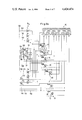
- FIG. 1 is a first simple embodiment of the invention employing triac circuit elements as the controlled circuit components;
- FIG. 2 is a second simple embodiment of the invention in which the controlled circuit components are full wave bridge rectifiers and diodes;
- FIG. 3 is a circuit arrangement similar to that of FIG. 2, however, employing only two bridge rectifier circuits and two controlled diodes for the three-phase motor windings;
- FIG. 4 illustrates three stages of a controlling circuit arrangement by means of which the r.p.m. of a three-phase motor may be controlled in three r.p.m. stages or ranges;
- FIGS. 5a and 5b illustrate controlled or controllable circuits with triacs arranged for cooperation with the controlling circuit arrangement according to FIG. 4, whereby however, the controlled circuits are arranged for a motor having divided motor windings;
- the example embodiment of FIG. 1 comprises a motor with the motor windings 20, 21 and 22.
- the motor windings of the three-phase motor are connected to a three-phase power supply symbolically represented by the terminals R, S, and T.
- Capacitors 27 are connected between the input ends of the windings 20 and 21 as well as 21 and 22 respectively.
- the output ends of the motor windings 20, 21, 22 are connected through controllable circuit means to the star point 23 of the motor drive circuit.
- the controllable circuit means comprise three triacs 24 the control terminal of which is connected to a control conductor 25 leading to a controlling circuit 26.
- a circuit interrupter for example a fuse, is conventionally interposed between each motor winding and the respective triac.
- the transistor TR operates substantially as a switch.
- the collector electrode of the transistor TR is connected through a limiting resistor W3 to one terminal of an auxiliary power source such as a d.c. power source.
- the other terminal of the d.c. power source is connected to the star point 23 of the motor drive circuit.
- the controlling circuit 26 further comprises a base resistor W2 and an adjustable resistor W1 connected between the collector terminal and the resistor W2. By adjusting the resistor W1 it is possible to adjust the base voltage of the transistor TR whereby the time duration during which the triacs 24 are conducting, may be manually adjusted for an open loop control.
- the star point 23 is connected to the negative terminal of the d.c. power source while the collector of the controlling transistor switch TR is connected through the limiting resistor W3 to the positive terminal of the d.c. power source.
- the capacitors 27, mentioned above, form with the windings 20, 21 and 22 resonance circuits for suppressing parasitic voltages in the form of harmonic waves.
- FIG. 2 The circuit arrangement of FIG. 2 is basically of the same structure as that of FIG. 1.
- the FIG. 2 embodiment comprises a full wave rectifier 28 operatively connected to its respective motor winding and to the star point 31 as well as to controllable diodes 29. More specifically, the motor windings are connected to one a.c. terminal of the respective full wave rectifier while the other a.c. terminal of each rectifier 28 is short circuited by a conductor 30.
- the negative d.c. terminal of each rectifier bridge circuit 28 is connected directly to the negative terminal of a d.c. power source connected to the star point 31.
- the positive terminals of the bridge rectifier circuits 28 are connected through respective controllable diodes, such as silicone controlled rectifier diodes, to a controlling conductor 32.
- the controlling conductor 32 is connected to the control transistor in the controlling circuit arrangement 26 corresponding to that described with reference to FIG. 1.
- Reverse blocking thyristors are suitable for embodying the controlled diodes 29.
- the cathode control terminal is connected to the control conductor 32.
- FIG. 3 illustrates basically an embodiment quite similar to that of FIG. 2. However, in FIG. 3 only two full wave rectifiers 33 are connected to the motor windings as shown.
- the controlled diodes 34 are also connected to the star point 35 leading to the negative terminal of a d.c. power source.
- the cathode control terminal of each controlled diode 34 is connected in common to the controlling circuit 26. As shown in FIG. 2 the a.c. terminals of the full wave bridge rectifiers 33 are connected between two adjacent motor windings.
- the controlling circuit 26 is the same as in FIGS. 1 and 2 and is connected to the positive terminal of the d.c. power source as shown in FIG. 1.
- the above described arrangements according to FIGS. 1, 2 and 3 control the r.p.m. of the three-phase motor automatically.
- the sum of the individual phase currents flows through the star points 23 in FIG. 1 or 31 in FIG. 2 or 35 in FIG. 3.
- the controlled diode circuit arrangement in each embodiment converts any occurring variations of the current flowing through the star point into respective voltage variations in response to the current input to the windings 20, 21, and 22.
- the controlling circuit 26, which is biased manually by the operator to a predetermined r.p.m. by the adjustment of the resistor W1, maintains the r.p.m by periodically switching the diode circuit arrangements into the conducting state for periodically applying the three-phase power source to energize the motor windings.
- the resistor W1 is adjusted to a predetermined r.p.m., the system will maintain that r.p.m. However, the r.p.m. may be changed by adjusting the resistor W1.
- circuit arrangements according to the invention for the open loop and/or closed loop control of pump motors particularly in heating systems.
- closed loop heating control systems including external temperature sensors and room thermostats
- the lead temperature of the exterior or room temperature is respectively adapted.
- Each radiator is also equipped with a thermostatic valve whereby an additional individual temperature control is possible for each room.
- FIGS. 4 and 5a as well as 5b show a practical embodiment of a circuit arrangement according to the invention in which the motor of a heating pump comprises a total of six windings.
- the windings connected to the three phase power supply lines R and S may be connected or switched in a crossover relationship. Thus, it is necessary to provide fourteen terminals between the controlling circuit arrangement and the windings.
- the simple controlling circuit arrangement 26 of the FIGS. 1, 2 and 3 is then replaced by the controlling circuit arrangement shown in FIG. 4.
- the circuit arrangement of FIG. 4 is simultaneously used for controlling in a closed and/or open loop fashion the pump r.p.m. in three different stages.
- the first pump r.p.m. is controlled by the circuit arrangement unit 40.
- the second stage is controlled by the unit 41 and the third stage is controlled by the unit 42.
- the input circuit connected to the d.c. power source is shown at 43.
- Each unit cooperates with a switch ST1, ST2, and ST3.
- a switch ST1, ST2, and ST3 At least the r.p.m. stage switches ST2 and ST3 are operated by a relay 44 which is controlled by a thermostatic sensor 45.
- Each of the circuit arrangement units 40, 41 and 42 comprises an optical coupling device for each phase R, S and T of the three-phase system and a control light emitting diode LED.
- Each optical coupling device in FIG. 4 is designated by two or three numbers which correspond to the above mentioned winding terminals 1 to 14 also shown in FIG. 5a.
- FIG. 5a is connected to FIG. 5b along the line 100, whereby the conductors or terminals 101 to 118 of FIG. 5a correspond to the terminals or conductors 101 to 118 of FIG. 5b.
- the d.c. power supply is provided by a rectifying unit 50 shown in FIG. 5b.
- the optical coupling devices OP of FIG. 4 form a component of circuit arrangements 51 shown in FIG. 5b. All the circuit arrangements 51 are identical to each other. Each circuit arrangement 51 comprises a phototransistor 52 which is light responsive and a switching transistor 53, as shown at the bottom of FIG. 5b.
- the circuit arrangements 51 are connected through their respective switching transistors 53 to thyristor circuits Th1, Th2 and Th3 for driving or controlling the energization of the motor windings 1 to 14.
- Each thyristor in the thyristor groups Th1, Th2 and Th3 is provided with a number corresponding to the number of the winding terminal to which the respective thyristor is connected.
- the switch S4 is used for connecting those motor windings in a crossover configuration which, as mentioned above, are adapted for such crossover connection for the purpose of starting the three-phase motor.
- FIGS. 4 and 5 shows that the method according to the invention for controlling in a closed or open loop fashion the r.p.m. of a three-phase operated motor may be performed by a circuit arrangement which is substantially less expensive than comparable prior art circuit arrangements because all the components are merely low voltage components and because power thyristors are not required.
- a circuit arrangement which is substantially less expensive than comparable prior art circuit arrangements because all the components are merely low voltage components and because power thyristors are not required.
- it was necessary to use such power thyristors because the prior art circuits required the switching of the entire current flowing through a winding by means of a power thyristor.
- the entire circuit arrangement can be realized at an economical price and in a compact structure.
- the galvanic separation between the controlling circuit arrangement and the controlled circuit arrangement by means of optical couplers has the advantage, among others, that the two circuits cannot influence each other in undesirable ways.
- FIG. 6 shows a further simple embodiment of the invention in a schematic manner.
- the motor windings are connected to respective terminals of a three-phase rectifier bridge circuit 60.
- At least one switching transistor 61 having a base resistor 62 in a controlling circuit arrangement 63 is connected to the respective terminals of the three-phase bridge rectifier circuit 60.
- the collector terminal of the switching transistor 61 is connected to the respective positive output terminal of the three-phase bridge rectifier circuit.
- the emitter terminal of the switching transistor 61 is connected to the negative terminal of the bridge rectifier circuit 60 and to the negative terminal member of the control input 64 of the circuit 63.
- the base of the switching transistor 61 is connected through the base transistor 62 to the positive terminal member of the control input 64.
- the arrangement of FIG. 6 receives at the control input 64 of the controlling circuit 63 a square waveform having a frequency corresponding to the base frequency of the three-phase power supply.
- the pulse width of the square waveform is variable. If it is desired to keep the frequency of the square waveform constant, it is possible to vary the frequency of the three-phase power supply for the motor windings in order to control the r.p.m. Further, it is possible to provide a combined control which involves varying the frequency of the three-phase power supply as well as the pulse width of the control input square waveform.
Landscapes
- Engineering & Computer Science (AREA)
- Power Engineering (AREA)
- Control Of Ac Motors In General (AREA)
Applications Claiming Priority (2)
| Application Number | Priority Date | Filing Date | Title |
|---|---|---|---|
| DE19803046406 DE3046406A1 (de) | 1980-12-10 | 1980-12-10 | Verfahren und schaltungsanordnung zum regeln bzw. steuern der drehzahl eines mit drehstrom betriebenen motors |
| DE3046406 | 1980-12-10 |
Publications (1)
| Publication Number | Publication Date |
|---|---|
| US4424474A true US4424474A (en) | 1984-01-03 |
Family
ID=6118725
Family Applications (1)
| Application Number | Title | Priority Date | Filing Date |
|---|---|---|---|
| US06/326,907 Expired - Fee Related US4424474A (en) | 1980-12-10 | 1981-12-02 | Method and circuit arrangement for controlling the r.p.m. of a three-phase motor |
Country Status (6)
| Country | Link |
|---|---|
| US (1) | US4424474A (fr) |
| EP (1) | EP0053799A1 (fr) |
| CA (1) | CA1172308A (fr) |
| DE (1) | DE3046406A1 (fr) |
| FI (1) | FI813841A7 (fr) |
| ZA (1) | ZA818482B (fr) |
Cited By (3)
| Publication number | Priority date | Publication date | Assignee | Title |
|---|---|---|---|---|
| US4978903A (en) * | 1988-07-19 | 1990-12-18 | A-Teollisuus Oy | Apparatus for the control of a three-phase a.c. motor, especially a squirrel-cage motor |
| US5541488A (en) * | 1994-04-11 | 1996-07-30 | Sundstrand Corporation | Method and apparatus for controlling induction motors |
| US20110012545A1 (en) * | 2008-03-22 | 2011-01-20 | Grundfos Management A/S | Method for controlling a multiphase electric motor operating in star-connected mode |
Families Citing this family (2)
| Publication number | Priority date | Publication date | Assignee | Title |
|---|---|---|---|---|
| DE19739780B4 (de) * | 1997-09-10 | 2007-03-22 | Sew-Eurodrive Gmbh & Co. Kg | Drehstrommotor |
| FR3094372B1 (fr) | 2019-03-26 | 2022-06-10 | Inst Mines Telecom | Procédé de fabrication d’une mousse à porosité fermée |
Citations (6)
| Publication number | Priority date | Publication date | Assignee | Title |
|---|---|---|---|---|
| US3309593A (en) | 1964-12-28 | 1967-03-14 | Combustion Eng | Reversing line starter |
| US3345549A (en) | 1965-03-09 | 1967-10-03 | Allis Louis Co | Rectifier bridge adjustable alternating current voltage control |
| US3376485A (en) | 1964-07-02 | 1968-04-02 | Toyo Electric Mfg Co Ltd | Control system for polyphase induction motors |
| US3387196A (en) | 1965-10-07 | 1968-06-04 | Gen Motors Corp | Speed control system for alternating current induction motors |
| US3437911A (en) | 1966-04-25 | 1969-04-08 | Gen Electric | Control circuit for controlling the power to an inductive load from a polyphase source |
| US3487345A (en) | 1968-10-18 | 1969-12-30 | Gen Electric | Electronic temperature regulation system using solid state devices and point contact sensors |
Family Cites Families (7)
| Publication number | Priority date | Publication date | Assignee | Title |
|---|---|---|---|---|
| DE1245486B (de) * | 1964-10-22 | 1967-07-27 | Schleicher Regelautomatik G M | Gleichrichtergruppe |
| DE1638512A1 (de) * | 1967-04-08 | 1970-05-21 | Pintsch Bamag Ag | Anordnung zur Regelung oder Steuerung der Drehzahl oder des Drehmomentes eines Drehstrom-Asynchronmo?ors |
| DE1613936B2 (de) * | 1967-09-15 | 1971-12-30 | Gebr. Honsberg, 5630 Remscheid | Mehrphasiger wechselstromsteller |
| DE2033513A1 (de) * | 1969-07-11 | 1971-01-28 | National Research Development Corp London | Schaltungsanordnung zur Drehzahl steuerung oder regelung eines Drei phasen Asynchronmotors |
| DE2007858A1 (de) * | 1970-02-20 | 1971-08-26 | Transformatoren Union Ag | Anordnung zur Regelung von Drehstrom Asynchronmaschinen |
| SE365673B (fr) * | 1972-10-18 | 1974-03-25 | Tour Agenturer Ab | |
| US3962613A (en) * | 1973-01-31 | 1976-06-08 | Wer Industrial Division Of Emerson Electric Co. | Polyphase AC motor control |
-
1980
- 1980-12-10 DE DE19803046406 patent/DE3046406A1/de not_active Withdrawn
-
1981
- 1981-12-01 FI FI813841A patent/FI813841A7/fi not_active Application Discontinuation
- 1981-12-02 US US06/326,907 patent/US4424474A/en not_active Expired - Fee Related
- 1981-12-03 EP EP81110098A patent/EP0053799A1/fr not_active Withdrawn
- 1981-12-07 ZA ZA818482A patent/ZA818482B/xx unknown
- 1981-12-07 CA CA000391673A patent/CA1172308A/fr not_active Expired
Patent Citations (6)
| Publication number | Priority date | Publication date | Assignee | Title |
|---|---|---|---|---|
| US3376485A (en) | 1964-07-02 | 1968-04-02 | Toyo Electric Mfg Co Ltd | Control system for polyphase induction motors |
| US3309593A (en) | 1964-12-28 | 1967-03-14 | Combustion Eng | Reversing line starter |
| US3345549A (en) | 1965-03-09 | 1967-10-03 | Allis Louis Co | Rectifier bridge adjustable alternating current voltage control |
| US3387196A (en) | 1965-10-07 | 1968-06-04 | Gen Motors Corp | Speed control system for alternating current induction motors |
| US3437911A (en) | 1966-04-25 | 1969-04-08 | Gen Electric | Control circuit for controlling the power to an inductive load from a polyphase source |
| US3487345A (en) | 1968-10-18 | 1969-12-30 | Gen Electric | Electronic temperature regulation system using solid state devices and point contact sensors |
Cited By (4)
| Publication number | Priority date | Publication date | Assignee | Title |
|---|---|---|---|---|
| US4978903A (en) * | 1988-07-19 | 1990-12-18 | A-Teollisuus Oy | Apparatus for the control of a three-phase a.c. motor, especially a squirrel-cage motor |
| US5541488A (en) * | 1994-04-11 | 1996-07-30 | Sundstrand Corporation | Method and apparatus for controlling induction motors |
| US20110012545A1 (en) * | 2008-03-22 | 2011-01-20 | Grundfos Management A/S | Method for controlling a multiphase electric motor operating in star-connected mode |
| US8796970B2 (en) * | 2008-03-22 | 2014-08-05 | Grundfos Management A/S | Method for controlling a multiphase electric motor operating in star-connected mode |
Also Published As
| Publication number | Publication date |
|---|---|
| ZA818482B (en) | 1982-10-27 |
| DE3046406A1 (de) | 1982-07-22 |
| FI813841L (fi) | 1982-06-11 |
| FI813841A7 (fi) | 1982-06-11 |
| EP0053799A1 (fr) | 1982-06-16 |
| CA1172308A (fr) | 1984-08-07 |
Similar Documents
| Publication | Publication Date | Title |
|---|---|---|
| KR960001071B1 (ko) | 전자적으로 스위칭되는 전력 리셉터클 | |
| JP7037656B2 (ja) | 電子スイッチおよび調光器 | |
| EP3533138B1 (fr) | Commutateur électronique et gradateur | |
| US20040227560A1 (en) | High speed bi-directional solid state switch | |
| US20050122747A1 (en) | Power supply system | |
| JPS63277468A (ja) | 位相制御された信号入力を有する電力制御回路 | |
| US8619443B2 (en) | System and method to boost voltage | |
| US9564832B2 (en) | Circuit for synchronously switching series connected electronic switches | |
| CN110784101B (zh) | 固态继电器、电力系统和控制电力系统中的电流的方法 | |
| US4424474A (en) | Method and circuit arrangement for controlling the r.p.m. of a three-phase motor | |
| US6356043B2 (en) | Motor controller power switch arrangement | |
| KR970060661A (ko) | 스위치드 릴럭턴스 모터(srm)의 컨버터 | |
| CA2179356C (fr) | Alimentation de controleurs d'energie en ligne et thermostat electronique dipole utilisant une telle alimentation | |
| US5498915A (en) | Electronically switched power receptacle | |
| JP2001112265A (ja) | インバータ装置及び電動機駆動装置 | |
| US3818308A (en) | Inverting bridge circuit | |
| US5162682A (en) | Solid state relay employing triacs and plurality of snubber circuits | |
| US3754177A (en) | Solid state controller | |
| US4494049A (en) | Commutating device for an electric motor supplied from a d-c voltage source | |
| US4318094A (en) | Interface device for remote control | |
| US20010026433A1 (en) | Demagnetizing circuit | |
| SU1348920A1 (ru) | Трансформаторный фазорегул тор | |
| GB2121248A (en) | Capacitive voltage dropper | |
| EP3021471A1 (fr) | Ensemble de convertisseur | |
| JPH03265460A (ja) | トランジスタ制御用電源回路 |
Legal Events
| Date | Code | Title | Description |
|---|---|---|---|
| AS | Assignment |
Owner name: FIRMA IWE INGENIEURGESELLSCHAFT FUR WIRTSCHAFTLICH Free format text: ASSIGNMENT OF ASSIGNORS INTEREST.;ASSIGNORS:DURR, WALTER;WEISSE, DIETRICH;SIMON, ULRICH;AND OTHERS;REEL/FRAME:004153/0182 Effective date: 19811125 |
|
| MAFP | Maintenance fee payment |
Free format text: PAYMENT OF MAINTENANCE FEE, 4TH YEAR, PL 96-517 (ORIGINAL EVENT CODE: M170); ENTITY STATUS OF PATENT OWNER: SMALL ENTITY Year of fee payment: 4 |
|
| MAFP | Maintenance fee payment |
Free format text: PAYMENT OF MAINTENANCE FEE, 8TH YEAR, PL 96-517 (ORIGINAL EVENT CODE: M171); ENTITY STATUS OF PATENT OWNER: SMALL ENTITY Year of fee payment: 8 |
|
| FEPP | Fee payment procedure |
Free format text: PAYOR NUMBER ASSIGNED (ORIGINAL EVENT CODE: ASPN); ENTITY STATUS OF PATENT OWNER: SMALL ENTITY |
|
| FEPP | Fee payment procedure |
Free format text: MAINTENANCE FEE REMINDER MAILED (ORIGINAL EVENT CODE: REM.); ENTITY STATUS OF PATENT OWNER: SMALL ENTITY |
|
| LAPS | Lapse for failure to pay maintenance fees | ||
| FP | Lapsed due to failure to pay maintenance fee |
Effective date: 19960103 |
|
| STCH | Information on status: patent discontinuation |
Free format text: PATENT EXPIRED DUE TO NONPAYMENT OF MAINTENANCE FEES UNDER 37 CFR 1.362 |