US4445203A - Memory device - Google Patents
Memory device Download PDFInfo
- Publication number
- US4445203A US4445203A US06/304,036 US30403681A US4445203A US 4445203 A US4445203 A US 4445203A US 30403681 A US30403681 A US 30403681A US 4445203 A US4445203 A US 4445203A
- Authority
- US
- United States
- Prior art keywords
- data line
- threshold level
- potential
- memory cells
- data
- Prior art date
- Legal status (The legal status is an assumption and is not a legal conclusion. Google has not performed a legal analysis and makes no representation as to the accuracy of the status listed.)
- Expired - Lifetime
Links
- 230000015654 memory Effects 0.000 claims abstract description 122
- 230000003111 delayed effect Effects 0.000 claims description 15
- 230000035945 sensitivity Effects 0.000 claims 18
- 230000008034 disappearance Effects 0.000 claims 3
- 239000004020 conductor Substances 0.000 claims 1
- 230000004048 modification Effects 0.000 description 11
- 238000012986 modification Methods 0.000 description 11
- 238000010586 diagram Methods 0.000 description 7
- 239000004065 semiconductor Substances 0.000 description 4
- 230000003068 static effect Effects 0.000 description 3
- 230000010354 integration Effects 0.000 description 2
- 238000004904 shortening Methods 0.000 description 2
- 238000010276 construction Methods 0.000 description 1
- 238000013500 data storage Methods 0.000 description 1
- 238000005516 engineering process Methods 0.000 description 1
- 230000006870 function Effects 0.000 description 1
- 238000000034 method Methods 0.000 description 1
- 238000004377 microelectronic Methods 0.000 description 1
- 239000007787 solid Substances 0.000 description 1
- 230000001360 synchronised effect Effects 0.000 description 1
Images


Classifications
-
- G—PHYSICS
- G11—INFORMATION STORAGE
- G11C—STATIC STORES
- G11C7/00—Arrangements for writing information into, or reading information out from, a digital store
- G11C7/06—Sense amplifiers; Associated circuits, e.g. timing or triggering circuits
- G11C7/062—Differential amplifiers of non-latching type, e.g. comparators, long-tailed pairs
-
- G—PHYSICS
- G11—INFORMATION STORAGE
- G11C—STATIC STORES
- G11C17/00—Read-only memories programmable only once; Semi-permanent stores, e.g. manually-replaceable information cards
- G11C17/08—Read-only memories programmable only once; Semi-permanent stores, e.g. manually-replaceable information cards using semiconductor devices, e.g. bipolar elements
- G11C17/10—Read-only memories programmable only once; Semi-permanent stores, e.g. manually-replaceable information cards using semiconductor devices, e.g. bipolar elements in which contents are determined during manufacturing by a predetermined arrangement of coupling elements, e.g. mask-programmable ROM
- G11C17/12—Read-only memories programmable only once; Semi-permanent stores, e.g. manually-replaceable information cards using semiconductor devices, e.g. bipolar elements in which contents are determined during manufacturing by a predetermined arrangement of coupling elements, e.g. mask-programmable ROM using field-effect devices
-
- G—PHYSICS
- G11—INFORMATION STORAGE
- G11C—STATIC STORES
- G11C7/00—Arrangements for writing information into, or reading information out from, a digital store
- G11C7/06—Sense amplifiers; Associated circuits, e.g. timing or triggering circuits
- G11C7/065—Differential amplifiers of latching type
-
- G—PHYSICS
- G11—INFORMATION STORAGE
- G11C—STATIC STORES
- G11C7/00—Arrangements for writing information into, or reading information out from, a digital store
- G11C7/06—Sense amplifiers; Associated circuits, e.g. timing or triggering circuits
- G11C7/067—Single-ended amplifiers
Definitions
- the present invention relates to a memory device with an improved sense amplifier.
- CMOS complementary metal-oxide-semiconductor
- CMOS complementary metal-oxide-semiconductor
- CMOS complementary metal-oxide-semiconductor
- sense amplifier The sense amplifier
- FIG. 1 shows a configuration of a general semiconductor read only memory (ROM). Illustrated in the figure are a column decoder 1, column lines (data lines) 2, column selecting MOS transistors 3, a row decoder 4, row lines (word lines) 5, MOS transistors 6 forming memory cells each of which is driven by the corresponding line 5, a load MOS transistor 7 for charging the lines 2, and a sense amplifier 8 with an output buffer.
- the transistors 3 and 6 are of the enhancement type.
- the transistor 7 is of the depletion type.
- FIG. 2 shows a simple equivalent circuit for illustrating the charge and discharge of either data line 2 shown in FIG. 1.
- resistance R7 represents an internal resistance of the load transistor 7.
- Resistance R6 is representative of a conduction resistance of the memory cell transistor 6.
- the symbols R6 and R7 are also used to indicate equivalent resistors for providing the corresponding resistances.
- Switches S3 and S6 represent ON and OFF functions of the transistors 3 and 6, respectively.
- a capacitance C indicates a total capacitance of the data line 2 and the sensing point S.
- the conduction resistance of the transistor 3 is much smaller than the resistance R7 and therefore is neglected. Alternately, it may be considered that the resistance R7 includes the conduction resistance of the transistor 3.
- FIG. 3 shows time varying curves of a charged voltage VC or a sense potential VS of the capacitance C shown in FIG. 2.
- the switch S3 is ON, while the switch S6 is OFF, and the line 2 is charged up to the power supply potential E.
- the switch S6 is ON.
- the line 2 is discharged to a dividend potential ⁇ R6/(R6+R7) ⁇ E, or a minimum potential Ed, by the resistances R6 and R7.
- the switch S6 is OFF. Then, the line 2 is charged up to the maximum potential E.
- a threshold level VTH for distinguishing logic 0 from logic 1 and vice versa is set midway between the potentials E and Ed.
- the stored data "logic 0" is sensed when the sense potential VS is less than the level VTH.
- the stored data "logic 1” is sensed when the sense potential VS is more than the level VTH. Accordingly, the read out time of the logic 0 is TL1, and the read out time of the logic 1 is TH1.
- a transistor with the shortest possible channel length and width is used for each memory cell in order to make the chip size small as possible.
- To reduce the resistance R6 as mentioned above results in enlarging the channel width the transistor 6. Therefore, the memory size and hence the chip size are also made large. This is the reason for the restriction in reducing the size of the resistance R6.
- the transistor size is further reduced while the memory capacity of the semiconductor memory is increased. Accordingly, the number of transistors connected to one data line 2 is correspondingly increased, resulting in the increase of a capacity of the data line 2. Consequently, the ratio of charge/discharge time of the data line 2 to the total read out time is increased (address data inputted to the memory data is read out from the output buffer 8). In the case of FIG. 2, this is equivalent to the increase of the capacitance C. Accordingly, it is impossible to to make both the read out times TL and TH small, and therefore, the selection of the read out times TL and TH must be a compromise between both the times.
- the read out times TL and TH can be changed by adjusting the threshold level VTH. Even this method involves a conflicting interrelation between the shortenings of the time TL and the time TH.
- the level VTH is set high, the time TL can be made short, but the time TH is long.
- the level VTH is set low, the time TH can be made short, though the time TL is long. Therefore, it is impossible to shorten both the read out times TL and TH, whatever threshold VTH is selected.
- the present invention therefore, has an object to provide a memory device with a sense amplifier capable of shortening a read out time of stored data.
- a memory device is provided with a sense amplifier having two threshold levels each for independently distinguishing a logic 0 stored in each memory cell from a logic 1 and vice versa.
- the threshold level of the sense amplifier is changed for detecting the data stored in a newly-selected memory cell in accordance with the data stored in the memory cell already selected.
- the threshold levels are a first threshold level VH equal to or slightly less than the maximum potential at a sensing point connected to the memory cells and a second threshold levl VL equal to or slightly more than the minimum potential at the sensing point.
- a logic 0 of the stored data is sensed when a potential VS at the sensing point is less than the first threshold level VH
- a logic 1 of the stored data is sensed when the potential Vs is more than the second threshold level VL. Since the two threshold levels VH and VL are independent of each other, it is possible to make both the read times of the logic 0 and logic 1 as short as possible. The read out times are little effected by the charge/discharge speed at the sensing point.
- FIG. 1 shows a configuration of a general ROM
- FIG. 2 shows a simple equivalent circuit for illustrating the charge and discharge of one data line of the ROM shown in FIG. 1;
- FIG. 3 shows a variation of the charge and discharge to and from a capacitance C shown in FIG. 2 with respect to time;
- FIG. 5 shows an embodiment of a circuitry of the sense amplifier shown in FIG. 4;
- FIGS. 6 and 6A to 6G are timing diagrams useful in explaining the operation of the circuitry shown in FIG. 5;
- FIG. 7 shows a circuit diagram of a sense amplifier according to the present invention which is suitable for a static RAM
- FIGS. 8A to 8C are timing diagrams useful in explaining the operation of the circuitry shown in FIG. 7;
- FIGS. 10A to 10E are timing diagrams illustrating a sequence of signals in the operation of the circuitry shown in FIG. 9;
- FIG. 11 is a circuit arrangement of a modification of FIG. 9;
- FIG. 12 is a circuit arrangement of another example of the circuitry of each of the comparators shown in FIG. 4;
- FIG. 13 diagrammatically shows a circuitry of a logic circuit connected to the comparators shown in FIG. 5 or FIG. 12;
- FIG. 15 illustrates a circuit arrangement of a modification of FIG. 13
- FIG. 17 illustrates a circuit arrangement of another modification of the logic circuit in FIG. 13;
- FIGS. 18A to 18G are a set of timing charts for illustrating the operation of the circuitry shown in FIG. 17;
- FIG. 19 illustrates a circuit arrangement of another embodiment of the sense amplifier shown in FIG. 4.
- the outputs a and b are inputted to a logic circuit 40.
- the circuit 40 produces an output e which becomes logic 0 immediately after the potential VS goes less than the level VH, and becomes logic 1 immediately after the potential VS goes more than the level VL.
- the output e is read out of the memory device as read out data by way of an output buffer 12.
- the transistors 22 to 28 form the first comparator 20.
- the first comparison output a is derived from the drain of the transistor 26.
- the second threshold level VL is obtained from a source of a depletion mode MOS transistor 52 in a voltage divider 50.
- a drain of the transistor 52 is connected to the power supply potential E.
- a source and a gate of the transistor 52 are coupled with a drain of an enhancement mode MOS transistor 54.
- a source of the transistor 54 is connected to a drain of an enhancement mode MOS transistor 56.
- a source of the transistor 56 is grounded. Gates of the transistors 54 and 56 are connected with the potential E.
- the sense potential VS is also applied to a gate of a depletion mode MOS transistor 32.
- a drain of the transistor 32 is coupled with the power supply potential E.
- a source of the transistor 32 is connected to a drain of an enhancement mode MOS transistor 36 and a gate of an enhancement mode MOS transistor 38.
- a gate of the transistor 36 and a drain of the transistor 38 are connected with a source of a depletion mode MOS transistor 34. Sources of the transistors 36 and 38 ar both grounded.
- a drain of the transistor 34 is connected to the potential E, and its gate is supplied with the second threshold level VL.
- the transistors 32 to 38 make up the second comparator 30. This arrangement is the same as that of said first comparator 20.
- the second comparison output b is derived from a drain of the transistor 36.
- the first comparison output a is applied to the first input of a NOR gate 42.
- the second comparison output b is applied to the first input of a NOR gate 44.
- a NOR output c of the gate 42 and a NOR output d of the gate 44 are applied to the first and second inputs of a NOR gate 46, respectively.
- a NOR output e of the gate 46 is inputted to a delay circuit 60.
- the circuit 60 includes integration circuits of two stages. Each of the integration circuits is comprised of an inverter and a CR low pass filter.
- a delayed output f outputted from the circuit 60 is applied to the second input of the gate 44.
- the output f is inverted into an inverted output g through an inverter 48.
- the output g is applied to the second input of the gate 42.
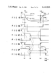
- FIGS. 6 and 6A to 6G illustrate the operation of the circuitry of the sense amplifier 10 shown in FIG. 5.
- the first threshold level VH is illustrated lower than the maximum potential E, while the second threshold level VL is illustrated higher than the minimum potential Ed for a better understanding. All the MOS transistors are of the N channel type. It is evident that the levels VH and VL are actually set at these levels.
- the level change from logic 1 to logic 0 of the output e is delayed by a given time period (t12 and t16) by the delay circuit 60.
- the delayed output f becomes logic 0 (FIG. 6F) and the inverted output g becomes logic 1 (FIG. 6G).
- the NOR output c returns in the level to logic 0 (FIG. 6C).
- the output b has a logic 0 (FIG. 6B).
- the logic 0 of the output f causes the output d to have a logic 1 (FIG. 6D).
- the output c becomes logic 0, while the output d becomes logic 1.
- the output c is delayed behind the output d by the signal passage time of the inverter 48. Therefore, the output e keeps its level at logic 0.
- the charging operation for the data line 2 starts.
- the sense potential VS substantially exponentially rises from the minimum potential Ed toward the maximum potential E (FIG. 6).
- the level changing operation from logic 0 to logic 1 at the output e at time t22 is delayed by a given time period (t22 to t26) by the circuit 60.
- the delayed output f is logic 1 (FIG. 6F) and the inverted output g is logic 0 (FIG. 6G).
- the output a is logic 1 (FIG. 6A), so that the NOR output c remains its logic 0 (FIG. 6C).
- the output b is also logic 1, so that the NOR output d remains its logic 0 (FIG. 6D).
- the NOR output e keeps its logic 1 level (FIG. 6E).
- the operation after time t26 is a repeat of the operation during the time period from time t10 to time t26.
- the stored data in the memory cells are read out as the output e.
- the output e is also logic 0, while when the stored data is logic 1, the output e is logic 1.
- the delay time in the delay circuit 60 is selected so as to satisfy the following relations.
- FIGS. 6 and 6E shows the following facts.
- the read out time TL is extremely short, which ranges from an instant (t10) that the memory cell with the logic 0 data is selected till the logic 0 data is read out (t12).
- the read out time TH is also extremely short, which ranges from an instant (t20) that the memory cell of logic 1 is selected till the logic 1 is read out (t22). Consequently, ROMs, static RAMs or the like of which the data read out speed is extremely high can be fabricated by using the sense amplifier according to the present invention.
- the transistors 54 and 56 in the divider 50 are not necessarily always in an ON state but may be turned ON when the comparison is made by a signal synchronized with the operation timing of the decoder 1.
- FIG. 7 shows a circuit arrangement of a sense amplifier of the invention which adapts well for a static RAM.
- the potential VS on a data line is inputted to a delay circuit 60.
- a delayed output h of the circuit 60 is level-inverted to an inverted output h by an inverter 62.
- the potential VS is applied to gates of enhancement mode MOS transistors 70 and 72. Drains of the transistors 70 and 72 are connected together to a source and a gate of a depletion mode MOS transistor 74.
- a drain of the transistor 74 is connected with a positive supply voltage VD.
- the voltage VD correspond to the potential E of FIG. 5.
- a source of the transistor 70 is coupled with a drain of an enhancement mode MOS transistor 76.
- a source of the transistor 72 is connected to a drain of an enhancement mode MOS transistor 78.
- a gate of the transistor 76 is connected with the voltage VD and a gate of the transistor 78 is connected to the output of the inverter 62.
- a potential VS of an inverted data line is applied to gates of enhancement mode MOS transistors 80 and 82. Drains of the transistors 80 and 82 are connected together to a source and a gate of a depletion mode MOS transistor 84. A drain of the transistor 84 is connected with the voltage VD. A source of the transistor 80 is connected to a drain of an enhancement mode MOS transistor 86. A source of the transistor 82 is coupled with a drain of an enhancement mode MOS transistor 88. A gate of the transistor 86 is connected to the voltage VD, and a gate of the transistor 88 is coupled with the output of the circuit 60. Sources of the transistors 76, 78, 86 and 88 are connected with a drain of a depletion mode MOS transistor 90. A gate and a source of the transistor 90 are connected together to another supply voltage VE corresponding to the ground potential in FIG. 5.
- the transistors 70 to 78 and the transistors 80 to 88 make up a differential amplifier 100 having a transistor 90 as a common impedance.
- the transconductance (gm) of the transistors 70 and 72 goes high, while the transconductance of the transistor 80 is low.
- the transistor 78 is OFF and the transistor 88 is turned ON, the transconductance of the transistors 80 and 82 goes high, while the transconductance of the transistor 70 is low.
- a difference between those transconductances (gm) puts the input level balance of the differential amplifier 100 into disorder. This is a key to the circuit of FIG. 7.
- FIGS. 8A to 8C graphically illustrate the operation of the FIG. 7 circuit.
- the sense potential VS, the output h, and output e are all logic 1
- the outputs VS, h and e are all logic 0.
- the transistor 70 is turned ON, while the transistors 72, 80 and 82 are turned OFF. In this case, the transistor 70 is a low gm, and the transistors 80 and 82 are a high gm.
- the potential VS starts to fall, while the potential VS starts to rise. If there is no difference among those gm's, the output e and e of the differential amplifier 100 are not level-inverted until time t34 when VS ⁇ VS. However, the level inversion in fact takes place at the outputs e and e even when VS>VS, since the transistors 80 and 82 supplied with the potential VS have high gm.
- the transistors 80 and 82 are turned ON, while the transistor 70 is turned OFF. Then, the output e is logic 0 and the output e is logic 1 (FIG. 8C).
- the delayed output h is logic 0 and the inverted output h is logic 1 (FIG. 8B).
- the transistor 88 is turned OFF.
- the transistor 82 is also cut off to zero the drain current of the transistor 82.
- the voltage drop by the transistor 84 becomes small, so that the potential of the output rises slightly (FIG. 8C). Because of a slight amount of the potential rise, the output e yet remains logic 0.
- the transistors 70 and 72 are both turned OFF and hence the potential of the output e keeps its state.
- the transistors 70 and 72 are slightly conductive even if the potential VS is a low potential. In this case, the logic 1 state of the output h turns ON the transistor 78. As a result, the voltage drop by the transistor 74 increases, so that the potential of the output e slightly falls (as indicated by a broken line during the time period t36 to t40 in FIG. 8C). However, since the potential drop is slight, the output e keeps the logic 1 level.
- the transistors 70, 72, 80 and 82 are preferably of the depletion mode type.
- the outputs h and h are logic 1 and logic 0, respectively (FIG. 8B). Then, the transistor 78 is turned OFF and the potential of the output e slightly rises (FIG. 8C). After time t46, the circuit state returns to that before time t30. If the transistors 80 and 82 are conductive under a condition that the VS is at a low level, the potential of the output e slightly drops while keeping the logic 1 state.
- the threshold level for detecting the sense potential VS is only one level VTH shown in FIG. 8A.
- the circuit arrangement according to the present invention has the two threshold levels; the first threshold level VH for detecting the logic 0 of the output e and the second threshold level VL for detecting the logic 1 of the output e. As seen from FIG. 8, if the level VH is set much closer to the maximum level of the potential VS, the read out time TL for the logic 0 is extremely short.
- the read out time TH for logic 1 is considerably short. In other words, a memory device at a high read out speed can be realized without speeding up the change of the potential VS.
- the transistor 82 has a higher gm than the transistor 70, resulting in setting the level VH high. If the transistor 72 is substituted by a plurality of transistors parallel connected, its gm is higher than that of the transistor 80. The high gm may also be obtained by increasing the sizes of the transistors 72 and 82. Alternately, the threshold voltage of the transistor 82 may be set lower than that of the transistor 70, and the threshold voltage of the transistor 72 may be set lower than that of the transistor 80.
- FIG. 9 shows an arrangement of a modification of the sense amplifier 10 shown in FIG. 4.
- a single comparator is used here, and either of two levels VH and VL is used as its comparison level.
- the first threshold level VH is used for the read out of logic 0
- the second threshold level VL is used for the read out of logic 1.
- the sense potential VS is applied to a gate of an enhancement mode MOS transistor 104 by way of a drain-source path of an enhancement mode MOS transistor 102.
- a gate of the transistor 104 is connected with a positive supply voltage VD via a source-drain path of a depletion mode MOS transistor 106.
- a gate of the transistor 106 is coupled with its source.
- a drain of the transistor 104 is connected with a gate and a source of a depletion mode MOS transistor 108.
- a drain of the transistor 108 is connected to the voltage VD.
- a source of the transistor 104 is connected with a drain of an enhancement mode MOS transistor 110.
- a gate of the transistor 110 is connected to the voltage VD through a source-drain path of a depletion mode MOS transistor 112 whose gate is coupled with its source.
- a gate of the transistor 110 receives the potential VS by way of a drain-source path of an enhancement mode MOS transistor 114.
- a source of the transistor 110 is connected with a drain of a depletion mode MOS transistor 116.
- a gate and a source of the transistor 116 are coupled with another supply voltage VE through a drain-source path of an enhancement mode MOS transistor 118.
- the voltage VE may be the ground level.
- a gate of the transistor 118 receives a chip enable signal CE.
- the signal CE becomes logic 1 when its memory chip is in an active state. When the signal CE is logic 0, circuit elements in the chip are powered off to prevent power dissipation.
- a drain of the transistor 116 is connected to a source of an enhancement mode MOS transistor 120.
- a gate of the transistor 120 is connected with the voltage VD via a source-drain path of a depletion mode MOS transistor 122.
- a gate of the transistor 122 is connected with its source.
- a drain of the transistor 120 is coupled with a source of an enhancement mode MOS transistor 124.
- a drain of the transistor 124 is connected to a gate and a source of a depletion mode MOS transistor 126.
- a gate of the transistor 124 is connected with a gate and a source of a depletion mode MOS transistor 128. Drains of the transistors 126 and 128 are connected to the voltage VD.
- a first threshold level VH is applied to a gate of the transistor 124 via a drain-source path of an enhancement mode MOS transistor 130.
- a gate of the transistor 120 is supplied with a second threshold level VL by way of a drain-source path of an enhancement mode MOS transistor 132.
- the level VH is obtained from a first threshold level source 140.
- the source 140 has series resistors 142 and 144 connected between the voltages VD and VE.
- a first divided voltage V1 which appears at a junction point of the resistors 142 and 144 is applied to a gate of an enhancement mode MOS transistor 146.
- a source of the transistor 146 is connected with the voltage VE, and its drain is connected to the transistor 130 via a drain-source path of an enhancement mode MOS transistor 148.
- a gate of the transistor 148 is coupled with the voltage VD.
- the level VL is obtained from a second threshold level source 150.
- the source 150 includes series resistors 152 and 154 connected between the voltages VD and VE.
- a second divided voltage V2 which appears at a junction point of the resistors 152 and 154 is applied to a gate of an enhancement mode MOS transistor 156.
- a source of the transistor 156 is connected with the voltage VE and its drain is coupled with the transistor 132 through a drain-source path of an enhancement mode MOS transistor 158.
- a gate of the transistor 158 is connected to the voltage VD.
- the sources 140 and 150 have the same configurations. Resistors 142, 144, 152 and 154 are so set that V2 is larger than V1. Since V2>V1, a drain current of the transistor 156 is larger than that of the transistor 146, if the sizes of the transistors 146 and 156 are equal to each other. Therefore, a drain potential VL of the transistor 158 is lower than a drain potential VH of the transistor 148.
- a drain of the transistor 104 is connected with a gate of an enhancement mode MOS transistor 160.
- a drain of the transistor 124 is connected with a gate of an enhancement mode MOS transistor 162.
- Drains of the transistors 160 and 162 are coupled with the voltage VD by way of source-drain paths of enhancement mode MOS transistors 164 and 166, respectively.
- Gates of the transistors 164 and 166 receive the chip enable signal CE.
- a source of the transistor 160 is connected to each drain and gate of each of enhancement mode MOS transistors 168 and 170.
- a source of the transistor 162 is respectively coupled with each gate and drain of the transistors 168 and 170. Sources of the transistors 168 and 170 are connected to the voltage VE.
- a signal Q which appears at a source of the transistor 160 is applied to a gate of an enhancement mode MOS transistor 172.
- a source of the transistor 172 is connected to the voltage VE by way of a drain-source path of an enhancement mode MOS transistor 174.
- a signal Q which appears at a source of the transistor 162 is fed to a gate of an enhancement mode MOS transistor 176.
- a source of the transistor 176 is connected with the voltage VE through a drain-source path of an enhancement mode MOS transistor 178. Drains of the transistors 172 and 176 are coupled with a gate and a source of a depletion mode MOS transistor 180.
- a drain of the transistor 180 is connected to the voltage VD.
- a signal i at a source of the transistor 180 is inputted to an inverter 182 and a gate of an enhancement mode MOS transistor 184.
- An output j from the inverter 182 is applied to a gate of an enhancement mode MOS transistor 186.
- a signal k which appears at a junction point of the transistors 184 and 186 is converted to an output e through inverters 188 and 190.
- the transistor 184 is connected between a source of the transistor 162 and an input terminal of the inverter 188.
- the transistor 186 is connected between the input terminal of the inverter 188 and an output terminal of the inverter 190.
- the components 182 to 190 form a latch circuit 192 to latch a level change of the signal Q.
- the signal Q is delayed by a predetermined time by a delay circuit 60.
- a delayed output A of the circuit 60 is inverted into an inverted output B by an inverter 194.
- the output A is applied to the gates of the transistors 102, 130 and 178. Further, the output B is fed to the gates of the transistors 114, 132 and 174.
- FIGS. 10A to 10E graphically illustrate the operation of the sense amplifier 10 shown in FIG. 9.
- the delayed output A is logic 1 and the inverted output B is logic 0 (FIG. 10B).
- the potential VS is applied to the transistor 104 and the first threshold level VH is applied to the transistor 124.
- VS>VH and the transistor 104 is ON and the transistor 124 is almost OFF. Accordingly, the signal Q is logic 1 and the inverted signal Q is logic 0 (FIG. 10C).
- the outputs A and B are level-inverted (FIG. 10B).
- the transistor 174 is turned ON.
- the logic states of the signals A and B are logic 0 and logic 1, respectively (FIG. 10B).
- the potential VS is applied to the transistor 110 and the second threshold level VL is applied to the transistor 120.
- the delayed outputs A and B are level-inverted (FIG. 10B).
- FIG. 11 shows a modification of the FIG. 9 circuit.
- the sense potential VS is inputted into the delay circuit 60.
- the remaining construction is the same as that of the FIG. 9 circuit.
- a basic operation of this modification is the same as that of the FIG. 9 circuit.
- the threshold voltage of each of the transistors 104, 110, 120, 124, 160, 162, 164 and 166 is preferably about 0 V.
- the reason for this is that the logic level "1" at the Q and Q may be set at higher potential.
- the voltages VH and VL are switched by the transistors 130 and 132, but the voltages V1 and V2 may be switched in place of them. In the latter case, the number of the transistors may be reduced.
- FIG. 12 shows another example of the comparators 20 and 30 shown in FIG. 4.
- the sense potential VS is inputted to a gate of an enhancement mode MOS transistor 200.
- a drain of the transistor 200 is connected with a gate and a source of a depletion mode MOS transistor 202.
- a source of the transistor 200 is connected to a drain of a depletion mode MOS transistor 204 and a source of an enhancement mode MOS transistor 206.
- a gate and a source of the transistor 204 are grounded.
- a drain of the transistor 206 is coupled with a gate and a source of a depletion mode MOS transistor 208. Drains of the transistors 202 and 208 are connected to a positive supply voltage VD.
- a gate of the transistor 206 receives a first threshold level VH.
- the level VH is derived from a first threshold level source (voltage divider) 140.
- a drain of the transistor 200 is coupled with a gate of an enhancement mode MOS transistor 210.
- a source of the transistor 210 is connected with a drain and a gate of enhancement mode MOS transistors 212 and 214. Sources of the transistors 212 and 214 are grounded.
- a gate of the transistor 212 and a drain of the transistor 214 are connected to a source of an enhancement mode MOS transistor 216.
- a gate of the transistor 216 is coupled with a drain of the transistor 206.
- a source of the transistor 210 is connected to gates of enhancement mode MOS transistors 218 and 220.
- a source of the transistor 216 is connected with gates of enhancement mode MOS transistors 222 and 224. Sources of the transistors 220 and 224 are grounded. Drains of the transistors 210, 216, 218 and 222 are connected to the voltage VD.
- a first comparison output a is produced from a drain of the transistor 220, and an inverted output a is produced from a drain of the transistor 224.
- the transistors 200 to 224 make up the first comparator 20.
- the comparison output a is logic 1 in the condition of VS>VH. When VS ⁇ VH, the output a is logic 0.
- the output a has an opposite logic level to that of the output a.
- the potential VS is also inputted to a gate of an enhancement mode MOS transistor 300.
- the second comparator 30 has the same configuration as that of the first comparator 20. In FIG. 12, the same lower two digits of reference numerals represent common transistors.
- the transistor 200 corresponds to the transistor 300.
- a gate of an enhancement mode MOS transistor 306 which forms a differential amplifier, together with the transistor 300, is applied with a second threshold level VL.
- the level VL is derived from a second threshold level source 150.
- a second comparison output b is derived from a drain of an enhancement mode MOS transistor 320.
- the output b is logic 1 when VS>VL, and is logic 0 when VS ⁇ VL. Further, an output b with an opposite level to that of the output b is obtained from a drain of an enhancement mode MOS transistor 324.
- FIG. 13 shows an arrangement of the logic circuit 40 connected to the comparators 20 and 30 shown in FIG. 12.
- the circuit 40 is comprised of only NAND gates.
- the output a is applied to a first input of a NAND gate 400.
- the output b is applied to a second input of the gate 400.
- the output b is also applied to first inputs of NAND gates 402 and 404.
- a NANDed output l of the gate 400 is inputted to first inputs of NAND gates 406 and 408.
- a second input of the gate 406 receives a NANDed output m of the gate 402.
- a NANDed output n of the gate 406 is inputted to a second input of the gate 402.
- the output n is level-inverted by an inverter 410.
- An inverted output o of the inverter 410 is applied to a second input of the gate 404.
- a NANDed output p of the gate 404 is inputted to a second input of the gate 408.
- the gate 408 produces a NANDed output e by NANDing of the outputs l and p.
- the output e is applied to the output buffer 12 in FIG. 4.
- FIGS. 14A to 14I graphically illustrate the operation of the sense amplifier shown in FIGS. 12 and 13.
- the memory cell with the stored data of logic 0 is selected and the potential VS is at the minimum level.
- the potential VS starts to rise.
- the signal b is logic 1 (FIG. 14C).
- FIG. 15 shows a modification of the logic circuit shown in FIG. 13. All the gates in the modification are NOR gates.
- the inverted signal b of the output b is inputted to first inputs of NOR gates 420 to 426.
- the output a is inputted to the second inputs of the gates 420 and 424.
- a NORed output q of the gate 420 is inputted to the second input of the gate 422.
- a NORed output r of the gate 422 is delayed by a delay circuit 60 to be a delayed output s.
- the output s is inputted to a third input of the gate 420 and an inverter 428.
- An inverted output t of the inverter 428 is inputted to a third input of the gate 424.
- a NORed output u of the gate 424 is inputted to a second input of the gate 426.
- a NORed output e of the gate 426 is applied to the output buffer 12 (FIG. 4).
- FIGS. 16A to 16I illustrate the operation of the circuit of FIG. 15.
- a memory cell of logic 0 is selected.
- FIG. 17 shows another modification of the logic circuit 40.
- the output a is inputted to gates of enhancement mode MOS transistors 430 and 450.
- the output b is inputted to gates of enhancement mode MOS transistors 432, 434, 452 and 454.
- Sources of the transistors 430, 434, 450 and 454 are grounded. Drains of the transistors 430 and 450 are connected with sources of the transistors 432 and 452, respectively. Drains of the transistors 434 and 454 are connected to sources of enhancement mode MOS transistors 436 and 456, respectively. Drains of the transistors 432 and 436 are connected to a gate and a source of a depletion mode MOS transistor 438, respectively. Drains of the transistors 452 and 456 are connected to a gate and a source of a depletion mode MOS transistor 458, respectively.
- a source of the transistor 438 is connected with a gate of an enhancement mode MOS transistor 440 and a gate of the transistor 456.
- a source of the transistor 440 is grounded, and its drain is connected with a gate of the transistor 436.
- a drain of the transistor 440 is connected to a gate and a source of a depletion mode MOS transistor 442.
- Drains of the transistors 438 and 442 are connected with a positive supply voltage VD.
- a source of the transistor 458 is connected with a gate of an enhancement mode MOS transistor 460.
- a source of the transistor 460 is grounded, and its drain is connected to a gate and a source of a depletion mode MOS transistor 462. Drains of the transistor 458 and 462 are connected to the voltage VD.
- the output e is derived from the drain of the transistor 460.
- FIGS. 18A to 18G graphically illustrate the operation of the circuit 40 shown in FIG. 17.
- VS>VL FIG. 18A
- the output e representing logic 1 of the stored data is produced (FIG. 18G).
- FIG. 19 shows another embodiment of the sense amplifier 10 shown in FIG. 4.
- the sense potential VS is inputted into a gate of an enhancement or depletion mode MOS transistor 470.
- a drain of the transistor 470 is connected to a gate of an enhancement mode MOS transistor 472.
- Sources of the transistors 470 and 472 are grounded through a resistor R1. Drains of the transistors 470 and 472 are connected to a positive supply voltge VD, through resistors R2 and R3. In the present embodiment, R2 ⁇ R3.
- the circuitry of FIG. 19 forms a hysteresis comparator with two threshold levels VH and VL.
- a source potential y at this time is VD ⁇ R1/(R1+R2). This corresponds to a first threshold level VH.
- VS ⁇ VH during the course of reading out the logic 0, the transistor 470 is turned OFF and the transistor 472 is turned ON.
- e logic 0.
- the source potential y drops to VD ⁇ R1/(R1+R3). This dropped potential level corresponds to a second threshold level VL.
- the threshold levels VH and VL in FIG. 19 can properly be changed in accordance with resistances of the resistors R1 to R3 and an input threshold level of the transistor 470.
- the resistor R1 may be coupled with a proper negative potential in place of ground.
- the MOS transistors used may be of N channel, P channel or C-MOS type.
- the P channel MOS transistors When the P channel MOS transistors are used, the polarities of the potential are inverted for those of the N channel transistors.
- the selection of the channel type of the transistors used are within the scope of the invention.
- the transistors used are not limited to the MOS FETs.
- the present invention is applicable for sense amplifiers using bipolar transistors or the like, or level sensors such as CCD shift registers.
- each MOS transistor as a memory cell may be electrically connected to or disconnected from the data line 2.
- the data storage may be realized by raising or dropping the threshold voltage of the MOS transistor of the memory cell.
Landscapes
- Read Only Memory (AREA)
- Static Random-Access Memory (AREA)
Applications Claiming Priority (2)
| Application Number | Priority Date | Filing Date | Title |
|---|---|---|---|
| JP55133559A JPS5856198B2 (ja) | 1980-09-25 | 1980-09-25 | 半導体記憶装置 |
| JP55-133559 | 1980-09-25 |
Publications (1)
| Publication Number | Publication Date |
|---|---|
| US4445203A true US4445203A (en) | 1984-04-24 |
Family
ID=15107631
Family Applications (1)
| Application Number | Title | Priority Date | Filing Date |
|---|---|---|---|
| US06/304,036 Expired - Lifetime US4445203A (en) | 1980-09-25 | 1981-09-21 | Memory device |
Country Status (4)
| Country | Link |
|---|---|
| US (1) | US4445203A (de) |
| EP (2) | EP0053428B1 (de) |
| JP (1) | JPS5856198B2 (de) |
| DE (2) | DE3177199D1 (de) |
Cited By (11)
| Publication number | Priority date | Publication date | Assignee | Title |
|---|---|---|---|---|
| US4480321A (en) * | 1981-08-24 | 1984-10-30 | Fujitsu Limited | Semiconductor memory device |
| US4488264A (en) * | 1982-06-10 | 1984-12-11 | Dshkhunian Valery | Transistor storage |
| US4572977A (en) * | 1982-12-24 | 1986-02-25 | Fujitsu Limited | Range checking comparator |
| US4636664A (en) * | 1983-01-10 | 1987-01-13 | Ncr Corporation | Current sinking responsive MOS sense amplifier |
| US4654826A (en) * | 1984-08-20 | 1987-03-31 | National Semiconductor Corporation | Single device transfer static latch |
| EP0250060A1 (de) * | 1986-02-27 | 1987-12-23 | Fujitsu Limited | Nichtflüchtige Halbleiter-Speichereinrichtung |
| US4719600A (en) * | 1986-02-18 | 1988-01-12 | International Business Machines Corporation | Sense circuit for multilevel storage system |
| US5023838A (en) * | 1988-12-02 | 1991-06-11 | Ncr Corporation | Random access memory device with integral logic capability |
| US5291452A (en) * | 1991-02-13 | 1994-03-01 | Sharp Kabushiki Kaisha | Sensing amplifier circuit for data readout from a semiconductor memory device |
| US5293345A (en) * | 1989-06-12 | 1994-03-08 | Kabushiki Kaisha Toshiba | Semiconductor memory device having a data detection circuit with two reference potentials |
| EP0905702A3 (de) * | 1997-09-30 | 1999-09-01 | Siemens Aktiengesellschaft | Selbstgetakteter sekundärer Abfühlverstärker mit Fensterdiskriminator |
Families Citing this family (8)
| Publication number | Priority date | Publication date | Assignee | Title |
|---|---|---|---|---|
| US4435658A (en) * | 1981-02-17 | 1984-03-06 | Burroughs Corporation | Two-level threshold circuitry for large scale integrated circuit memories |
| DE3381955D1 (de) * | 1982-07-26 | 1990-11-29 | Toshiba Kawasaki Kk | Halbleiterspeicheranlage mit datenuebertragungs- und erkennungsmitteln. |
| JPS62222498A (ja) * | 1986-03-10 | 1987-09-30 | Fujitsu Ltd | 消去及び書き込み可能な読み出し専用メモリ |
| US4831284A (en) * | 1988-03-22 | 1989-05-16 | International Business Machines Corporation | Two level differential current switch MESFET logic |
| JPH0274665A (ja) * | 1988-09-10 | 1990-03-14 | Katsuo Shinoda | 衣服用生地延反コンベヤ及び該生地の裁断方法 |
| JP2530055B2 (ja) * | 1990-08-30 | 1996-09-04 | 株式会社東芝 | 半導体集積回路 |
| US5272674A (en) * | 1992-09-21 | 1993-12-21 | Atmel Corporation | High speed memory sense amplifier with noise reduction |
| US5455802A (en) * | 1992-12-22 | 1995-10-03 | Sgs-Thomson Microelectronics, Inc. | Dual dynamic sense amplifiers for a memory array |
Citations (4)
| Publication number | Priority date | Publication date | Assignee | Title |
|---|---|---|---|---|
| US3953839A (en) * | 1975-04-10 | 1976-04-27 | International Business Machines Corporation | Bit circuitry for enhance-deplete ram |
| US4094008A (en) * | 1976-06-18 | 1978-06-06 | Ncr Corporation | Alterable capacitor memory array |
| US4123799A (en) * | 1977-09-19 | 1978-10-31 | Motorola, Inc. | High speed IFGET sense amplifier/latch |
| US4134151A (en) * | 1977-05-02 | 1979-01-09 | Electronic Memories & Magnetics Corporation | Single sense line memory cell |
Family Cites Families (3)
| Publication number | Priority date | Publication date | Assignee | Title |
|---|---|---|---|---|
| US3648071A (en) * | 1970-02-04 | 1972-03-07 | Nat Semiconductor Corp | High-speed mos sense amplifier |
| US4023122A (en) * | 1975-01-28 | 1977-05-10 | Nippon Electric Company, Ltd. | Signal generating circuit |
| JPS5824874B2 (ja) * | 1979-02-07 | 1983-05-24 | 富士通株式会社 | センス回路 |
-
1980
- 1980-09-25 JP JP55133559A patent/JPS5856198B2/ja not_active Expired
-
1981
- 1981-09-16 EP EP81304262A patent/EP0053428B1/de not_active Expired
- 1981-09-16 EP EP86201858A patent/EP0227128B1/de not_active Expired
- 1981-09-16 DE DE8686201858T patent/DE3177199D1/de not_active Expired - Lifetime
- 1981-09-16 DE DE8181304262T patent/DE3176940D1/de not_active Expired
- 1981-09-21 US US06/304,036 patent/US4445203A/en not_active Expired - Lifetime
Patent Citations (4)
| Publication number | Priority date | Publication date | Assignee | Title |
|---|---|---|---|---|
| US3953839A (en) * | 1975-04-10 | 1976-04-27 | International Business Machines Corporation | Bit circuitry for enhance-deplete ram |
| US4094008A (en) * | 1976-06-18 | 1978-06-06 | Ncr Corporation | Alterable capacitor memory array |
| US4134151A (en) * | 1977-05-02 | 1979-01-09 | Electronic Memories & Magnetics Corporation | Single sense line memory cell |
| US4123799A (en) * | 1977-09-19 | 1978-10-31 | Motorola, Inc. | High speed IFGET sense amplifier/latch |
Cited By (12)
| Publication number | Priority date | Publication date | Assignee | Title |
|---|---|---|---|---|
| US4480321A (en) * | 1981-08-24 | 1984-10-30 | Fujitsu Limited | Semiconductor memory device |
| US4488264A (en) * | 1982-06-10 | 1984-12-11 | Dshkhunian Valery | Transistor storage |
| US4572977A (en) * | 1982-12-24 | 1986-02-25 | Fujitsu Limited | Range checking comparator |
| US4636664A (en) * | 1983-01-10 | 1987-01-13 | Ncr Corporation | Current sinking responsive MOS sense amplifier |
| US4654826A (en) * | 1984-08-20 | 1987-03-31 | National Semiconductor Corporation | Single device transfer static latch |
| US4719600A (en) * | 1986-02-18 | 1988-01-12 | International Business Machines Corporation | Sense circuit for multilevel storage system |
| EP0250060A1 (de) * | 1986-02-27 | 1987-12-23 | Fujitsu Limited | Nichtflüchtige Halbleiter-Speichereinrichtung |
| US4799194A (en) * | 1986-02-27 | 1989-01-17 | Fujitsu Limited | Semiconductor random access nonvolatile memory device with restore and control circuits |
| US5023838A (en) * | 1988-12-02 | 1991-06-11 | Ncr Corporation | Random access memory device with integral logic capability |
| US5293345A (en) * | 1989-06-12 | 1994-03-08 | Kabushiki Kaisha Toshiba | Semiconductor memory device having a data detection circuit with two reference potentials |
| US5291452A (en) * | 1991-02-13 | 1994-03-01 | Sharp Kabushiki Kaisha | Sensing amplifier circuit for data readout from a semiconductor memory device |
| EP0905702A3 (de) * | 1997-09-30 | 1999-09-01 | Siemens Aktiengesellschaft | Selbstgetakteter sekundärer Abfühlverstärker mit Fensterdiskriminator |
Also Published As
| Publication number | Publication date |
|---|---|
| EP0053428A2 (de) | 1982-06-09 |
| DE3176940D1 (en) | 1988-12-22 |
| EP0053428B1 (de) | 1988-11-17 |
| EP0227128A3 (en) | 1987-10-28 |
| DE3177199D1 (de) | 1990-08-16 |
| EP0053428A3 (en) | 1984-04-04 |
| JPS5758297A (en) | 1982-04-07 |
| EP0227128B1 (de) | 1990-07-11 |
| EP0227128A2 (de) | 1987-07-01 |
| JPS5856198B2 (ja) | 1983-12-13 |
Similar Documents
| Publication | Publication Date | Title |
|---|---|---|
| US4445203A (en) | Memory device | |
| US6181591B1 (en) | High speed CAM cell | |
| US4984201A (en) | Semiconductor storage device with common data line structure | |
| US3967252A (en) | Sense AMP for random access memory | |
| US6400594B2 (en) | Content addressable memory with potentials of search bit line and/or match line set as intermediate potential between power source potential and ground potential | |
| EP0130910A2 (de) | Leseverstärker | |
| EP0212665B1 (de) | Leseverstärker für statischer Speicher | |
| EP0834883B1 (de) | Nichtflüchtige Halbleiterspeicheranordnung | |
| JPH08181548A (ja) | 差動増幅回路、cmosインバータ、パルス幅変調方式用復調回路及びサンプリング回路 | |
| US5208773A (en) | Semiconductor memory device having bit lines and word lines different in data reading and data writing | |
| US4131951A (en) | High speed complementary MOS memory | |
| EP0368328B1 (de) | Adressenübergangsabfühlschaltung | |
| JPH04238197A (ja) | センスアンプ回路 | |
| US4447893A (en) | Semiconductor read only memory device | |
| US6816425B2 (en) | Balanced sense amplifier control for open digit line architecture memory devices | |
| JPH0743933B2 (ja) | 遷移検出回路 | |
| JPH0344400B2 (de) | ||
| US5654926A (en) | Semiconductor memory device | |
| US4926379A (en) | Data read circuit for use in semiconductor memory device | |
| US5204838A (en) | High speed readout circuit | |
| NL8800893A (nl) | Schrijf-leesschakeling. | |
| GB1484941A (en) | High density high speed random access memory device | |
| KR940008139B1 (ko) | 반도체 메모리 장치의 데이타 감지 증폭회로 | |
| JPS5938674B2 (ja) | 記憶装置 | |
| JPH0793028B2 (ja) | 半導体記憶装置 |
Legal Events
| Date | Code | Title | Description |
|---|---|---|---|
| AS | Assignment |
Owner name: TOKYO SHIBAURA DENKI KABUSHIKI KAISHA; 72 HORIKAWA Free format text: ASSIGNMENT OF ASSIGNORS INTEREST.;ASSIGNOR:IWAHASHI, HIROSHI;REEL/FRAME:003932/0344 Effective date: 19810902 |
|
| STCF | Information on status: patent grant |
Free format text: PATENTED CASE |
|
| FPAY | Fee payment |
Year of fee payment: 4 |
|
| FEPP | Fee payment procedure |
Free format text: PAYOR NUMBER ASSIGNED (ORIGINAL EVENT CODE: ASPN); ENTITY STATUS OF PATENT OWNER: LARGE ENTITY |
|
| FPAY | Fee payment |
Year of fee payment: 8 |
|
| FPAY | Fee payment |
Year of fee payment: 12 |