US4452090A - Ultrasonic flowmeter - Google Patents
Ultrasonic flowmeter Download PDFInfo
- Publication number
- US4452090A US4452090A US06/379,240 US37924082A US4452090A US 4452090 A US4452090 A US 4452090A US 37924082 A US37924082 A US 37924082A US 4452090 A US4452090 A US 4452090A
- Authority
- US
- United States
- Prior art keywords
- phase
- ultrasonic
- gas
- transducer
- signal
- Prior art date
- Legal status (The legal status is an assumption and is not a legal conclusion. Google has not performed a legal analysis and makes no representation as to the accuracy of the status listed.)
- Expired - Lifetime
Links
- 238000011144 upstream manufacturing Methods 0.000 claims abstract description 15
- 238000013459 approach Methods 0.000 claims abstract description 9
- 238000000034 method Methods 0.000 claims description 3
- 230000003213 activating effect Effects 0.000 claims description 2
- 230000004913 activation Effects 0.000 claims 1
- 239000007789 gas Substances 0.000 abstract description 35
- 230000010363 phase shift Effects 0.000 abstract description 10
- 238000005259 measurement Methods 0.000 abstract description 6
- 230000000712 assembly Effects 0.000 description 17
- 238000000429 assembly Methods 0.000 description 17
- GQPLMRYTRLFLPF-UHFFFAOYSA-N Nitrous Oxide Chemical compound [O-][N+]#N GQPLMRYTRLFLPF-UHFFFAOYSA-N 0.000 description 6
- 230000008859 change Effects 0.000 description 6
- 238000002604 ultrasonography Methods 0.000 description 5
- QVGXLLKOCUKJST-UHFFFAOYSA-N atomic oxygen Chemical compound [O] QVGXLLKOCUKJST-UHFFFAOYSA-N 0.000 description 4
- 229910052760 oxygen Inorganic materials 0.000 description 4
- 239000001301 oxygen Substances 0.000 description 4
- 230000029058 respiratory gaseous exchange Effects 0.000 description 4
- 230000007423 decrease Effects 0.000 description 3
- 230000000694 effects Effects 0.000 description 3
- 239000001272 nitrous oxide Substances 0.000 description 3
- 230000000630 rising effect Effects 0.000 description 3
- 238000010586 diagram Methods 0.000 description 2
- 238000000926 separation method Methods 0.000 description 2
- 230000004075 alteration Effects 0.000 description 1
- XAGFODPZIPBFFR-UHFFFAOYSA-N aluminium Chemical compound [Al] XAGFODPZIPBFFR-UHFFFAOYSA-N 0.000 description 1
- 229910052782 aluminium Inorganic materials 0.000 description 1
- 239000003994 anesthetic gas Substances 0.000 description 1
- 230000002457 bidirectional effect Effects 0.000 description 1
- 238000004140 cleaning Methods 0.000 description 1
- 238000004891 communication Methods 0.000 description 1
- 230000005494 condensation Effects 0.000 description 1
- 238000009833 condensation Methods 0.000 description 1
- 238000012937 correction Methods 0.000 description 1
- 230000008878 coupling Effects 0.000 description 1
- 238000010168 coupling process Methods 0.000 description 1
- 238000005859 coupling reaction Methods 0.000 description 1
- 238000012864 cross contamination Methods 0.000 description 1
- 239000013078 crystal Substances 0.000 description 1
- 230000005611 electricity Effects 0.000 description 1
- 239000012530 fluid Substances 0.000 description 1
- 239000003193 general anesthetic agent Substances 0.000 description 1
- 238000012797 qualification Methods 0.000 description 1
- 230000000241 respiratory effect Effects 0.000 description 1
- 230000004044 response Effects 0.000 description 1
- 238000005070 sampling Methods 0.000 description 1
- 229920000260 silastic Polymers 0.000 description 1
- 229920002379 silicone rubber Polymers 0.000 description 1
- 239000000126 substance Substances 0.000 description 1
- 230000000007 visual effect Effects 0.000 description 1
- XLYOFNOQVPJJNP-UHFFFAOYSA-N water Substances O XLYOFNOQVPJJNP-UHFFFAOYSA-N 0.000 description 1
Images
Classifications
-
- G—PHYSICS
- G01—MEASURING; TESTING
- G01F—MEASURING VOLUME, VOLUME FLOW, MASS FLOW OR LIQUID LEVEL; METERING BY VOLUME
- G01F1/00—Measuring the volume flow or mass flow of fluid or fluent solid material wherein the fluid passes through a meter in a continuous flow
- G01F1/66—Measuring the volume flow or mass flow of fluid or fluent solid material wherein the fluid passes through a meter in a continuous flow by measuring frequency, phase shift or propagation time of electromagnetic or other waves, e.g. using ultrasonic flowmeters
- G01F1/667—Arrangements of transducers for ultrasonic flowmeters; Circuits for operating ultrasonic flowmeters
- G01F1/668—Compensating or correcting for variations in velocity of sound
-
- G—PHYSICS
- G01—MEASURING; TESTING
- G01F—MEASURING VOLUME, VOLUME FLOW, MASS FLOW OR LIQUID LEVEL; METERING BY VOLUME
- G01F1/00—Measuring the volume flow or mass flow of fluid or fluent solid material wherein the fluid passes through a meter in a continuous flow
- G01F1/66—Measuring the volume flow or mass flow of fluid or fluent solid material wherein the fluid passes through a meter in a continuous flow by measuring frequency, phase shift or propagation time of electromagnetic or other waves, e.g. using ultrasonic flowmeters
- G01F1/667—Arrangements of transducers for ultrasonic flowmeters; Circuits for operating ultrasonic flowmeters
Definitions
- the present invention relates to ultrasonic flowmeters of the type that measure time of flight of an ultrasonic signal transmitted and received alternately between a pair of oppositely disposed transducers.
- Such flowmeters have included vortex-shedding type, rotameters featuring various shaped rotating vanes or blades, hot wire anemometers, but all have certain disadvantages due to the particular need for accuracy over various flow ranges and in the presence of a particular environment.
- the flowmeter Since relative low pressures are experienced in the patient's breathing circuit, the flowmeter must be designed so as to present a minimum resistance to breathing and introduce minimal pressure drop in the system. Further qualifications of such flowmeters are that they must be easily cleanable or, in the alternative, be isolated completely from the flow of gas in the patient circuit to prevent cross-contamination between patients. A relatively fast response time is needed so that attending personnel can keep an accurate and instantaneous record of the conditions of gases supplied to or from the patient. As such, therefore, the flowmeter should also have bidirectional capability.
- Ultrasonic transducers are commercially available and are capable of acting both as transmitters and receivers.
- Such flowmeters may be of the single transducer type utilizing Doppler frequency shift measurement or time-of-flight measurement which utilize more than one transducer and measure the actual time elapsed as the transmitted signal travels from one transducer to the other.
- the former approach may have some inherent disadvantages, in that it does not measure a time average velocity but may interpret peak velocities.
- the Doppler technique requires a flow media that is an efficient reflector of the acoustic energy and such is not normally the case in patient breathing circuits.
- phase angle difference exceeds 360°.
- Normally, to measure the phase angle shift one establishes a phase reference at zero flow and measures the shift recognized by the receiving transducer. When that phase shift exceeds 360° the flowmeter cannot readily distinguish the true phase angle shift and therefore the result is ambiguous.
- gas density affects sound velocity and in clinical applications, it is common to have a gas stream to be analyzed that contains both air and nitrous oxide.
- the sound velocity of air at 20° C. is 342 meters/sec. and of nitrous oxide is 273 meters/sec.
- the zero flow phase shift at 100 kHz is at least 660° and is thus beyond the capability of present ultrasonic flowmeter systems, using the phase measurement approach.
- the ultrasonic flowmeter of the present invention utilizes a pair of oppositely disposed transducers arranged about the conduit through which the gas flows to be measured. As described with respect to the prior art, the present flowmeter measures direct time of flight by means of phase shift in both the upstream and the downstream directions.
- the ultrasonic transducers are located at a tilt angle to the mean flow direction of the measured gas and that angle ⁇ thus changes somewhat the equation of Plaut and Webster to the following: ##EQU2## by introducing the cosine function of the tilt angle.
- the difficulty with phase ambiguity occurring upon a phase shift in excess of 360° has been solved by utilizing a "floating reference phase" where the reference phase, from which the phase shift is measured, is determined and set by the microcomputer and therefore can be changed as necessary in the event the gas composition causes an effective flow phase shift in excess of 360°.
- the microcomputer monitors the status of the present zero flow phase by determining an average value of ⁇ u and ⁇ d , thus eliminating the effect of the gas velocity on the phase shift.
- the microcomputer thus knows the zero flow phase as determined by the gas composition within the conduit and, as that zero flow phase approaches a predetermined limit, i.e. 90° or 270°, the computer alters the phase reference to a new position to avoid the 360° ambiguity.
- the timer clock is divided into a plurality of phases and the microcomputer can select the correct phase to be used as a phase reference upon determining the zero flow phase for the particular gas concentration at that time and, at the same time, keep track of the phase reference changes so that the integer portion (2 n ⁇ ) can be continually corrected for an umlimited shift in phase angle.
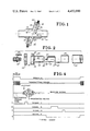
- FIG. 1 is a side view, partly in cross section, showing a pair of transducers mounted on a conduit containing the gas being measured;
- FIG. 2 is an exploded view of an ultrasonic transducer used with the present invention
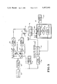
- FIG. 3 is a block schematic circuit diagram of the circuitry used to carry out the invention.
- FIG. 4 is illustrative of various signal wave forms at locations in the circuitry shown in FIG. 3.
- FIG. 1 there is shown a side view, partly in cross-section of a pair of ultrasonic transducer assemblies 10 and 12 oppositely mounted on a conduit 14 through which moves the particular gas to be measured.
- arrows 16 depict the direction of the gas flow through conduit 14.
- the transducer assemblies 10 and 12 are contained within cylindrical walls 18, 20 respectively which extend outwardly from the conduit 14 and are in communication with the flow of gas therein. As shown, the cylindrical walls 18 and 20 are disposed opposite and coaxial to each other and have an axis that meets the main axis of the path of gas flowing through conduit 15 at an angle ⁇ . In the preferred embodiment, that angle ⁇ is approximately 60° for a spacing or distance between the transducer assemblies 10 and 12 of about 1.06 inches.
- the cylindrical walls 18 and 20 provide mounting means for the transducer assemblies 10 and 12 so as to keep the transducer assemblies 10 and 12 out of the main flow of the gas in conduit 14.
- a minor dead space is created by the use of cylindrical walls 18 and 20, however such causes minor, if any, inaccuracy in making flow determinations.
- recessing transducer assemblies 10 and 12 as shown they present no obstruction to the normal flow of gas through conduit 14 and, therefore, introduce negligible flow resistance.
- transducer assemblies 10 and 12 within cylindrical walls 18 and 20 may be by a wide variety of means, however, as shown, a pair of releasable clips 22 (only one of each pair being shown) can be mounted on the transducer assemblies 10 and 12 and clip into suitable recesses 24 formed in the exterior surface of each of the cylindrical walls 18 and 20.
- the transducer assemblies 10 and 12 are thus readily removable from the cylindrical walls 18 and 20 for cleaning, replacement or the like.
- transducer assemby 10 is similarly constructed for positioning within cylindrical walls 18 and 20.
- the transducer assembly 10 comprises a housing 26 having a cylindrically shaped opening 28 which tightly receives the transducer 30.
- the transducer 30 can be obtained commercially and one suitable model is Channel Industries 5500 II having a resonant frequency of about 100 kHz and being about 0.5 inches long with a diameter of about 0.375 inches.
- a plurality of silicon rubber rails 32 extend along the length of cylindrically shaped opening 28 and serve to provide acoustic decoupling to isolate the transducer 30 acoustically from the housing 26.
- Suitable electrical lead wires 34 from both surfaces of the transducer 30 may be led through opening 36 in the housing 26 for outside electrical connections. Further acoustic decoupling is provided by a silastic pad 38 which separates transducer 30 from the rear surface of cylindrically shaped opening 28. Grounding of the aluminum housing 26 also serves to provide electrostatic shielding between the two transducers used with this invention.
- a film heater 40 Surrounding the outer cylindrical surface of the housing 26 is fitted a film heater 40 having electrical wires 42 for connection to a source of electricity.
- the film heater 40 retains the temperature of transducer 30 at about 40° C. to prevent water condensation on any exposed surface of transducer 30.
- a sleeve 44 which protects the film heater 40 and retains the film heater 40 in good thermal contact with the transducer 30.
- the sleeve 44 fits within annular groove 43 formed in the housing 26 and electrical wires 42 are lead through an aperture 45.
- a cap 46 for various electrical connections is secured to housing 26 by means such as cap screws 48 and a coaxial connector 50 is mounted on the cap 46 to provide external connections for the transducer 30 and film heater 40.
- FIGS. 3 and 4 the electronic circuitry of FIG. 3 is exemplified by the wave forms of signals depicted in FIG. 4.
- FIG. 3 there is shown a schematic diagram of the electronic circuitry used with the present invention and including an oscillator 52 that provides a square wave of predetermined frequency.
- an oscillator 52 that provides a square wave of predetermined frequency.
- a crystal controlled oscillator is used and which generates a square wave signal at 100 kHz for driving the preferred ultrasonic transducer.
- the oscillator 52 provides the square wave signal to a transmitting driver 54 which amplifies that signal to the necessary amplitude and power requirements to drive the transducer.
- Oscillator 52 also provides the square wave signal both to the control logic circuitry 56 that generates a series of timed pulses that will be later explained and also to phase divider 58.
- the signal from the transmitting driver 54 powers the ultrasonic transducer assembies 10 and 12 (note FIG. 1). As shown in FIG. 1, the transducer assembly 10 sends the ultrasound in the downstream direction of the gas being analyzed while the transducer assembly 12 sends its ultrasound in the upstream direction of such gas. Switches 60 and 62 control the signal from transmitting driver 54 to, respectively, transducer assemblies 10 and 12.
- the signal from one of those transducers assemblies is amplified, respectively, by amplifiers 64 and 66 and fed into zero crossing detectors 68 and 70 where the sinusoidal signal shape from the amplifiers 64 and 66 is reshaped into a square pulse train.
- a further set of switches 72 and 74 receives the signal from each of the zero crossing detectors 68 and 70 and, when one of the switches 72 or 74 is in the closed position, feeds the signal into a digital phase detector 76 for phase determination.
- the digital phase detector 76 compares the phase of the signals from zero crossing detectors 68 and 70 with a phase reference provided by multiplexer 78 as will be explained.
- a ⁇ is determined by the digital phase detector 76 for both a downstream direction, i.e. when transducer assembly 10 is transmitting and an upstream direction, i.e. when transducer assembly 12 is transmitting.
- ⁇ u and ⁇ d are those fed into the microprocessor 80 which perform several functions.
- the microprocessor 80 can utilize the equation: ##EQU3## to determine the flow velocity, the other parameters of the equation being known, in this instance, f is the operating frequency (100 kHz) L is the effective transducer separation and ⁇ is the tilt angle of the transducer assemblies 10 and 12 to the main axis of the flowing gas. That flow rate calculation can thus be calculated by the flow rate calculator 82 and the result provided to a read out device such as flowrate output device 84 where a visual indication of the flow velocity may be readily viewed by the user.
- Microprocessor 80 also, however, determines an average ⁇ u and ⁇ d to be used to change the phase reference provided by multiplexer 78 to the digital phase detector 76. In the case of zero flow, the upstream phase change and downstream phase change will be the same and depend upon the composition of the gas being detected. As will be explained, when there is flow, the average of the two variables ⁇ u and ⁇ d is therefore computed by microprocessor 80, and, as that average value reaches a predetermined limit, it is sensed by the phase limit detector 86 and a change made in the phase reference by phase control 88 so that the multiplexer 78 provides a different phase reference to the digital phase detector 76 to provide the phase shift comparisons with signals from zero crossing detectors 68 and 70.
- FIG. 4 shows the wave form of the various signals involved in the circuitry.
- FIG. 4 shows the wave form for the signals A, B, C, D, and E which are generated by the control logic circuitry 56 from the pulses from oscillator 52.
- signal A is generated and controls the closing of switch 60, thus activating transducer assembly 10 as a transmitter of ultrasound through the gas stream in the downstream direction to transducer assembly 12 which acts, during this time, as a receiver.
- the length of such signal may be about 100 ⁇ sec., thus the square wave pulse from transmitting driver 54 at or about the resonant frequency of the particular transducer, actuates the same.
- switch 62 is open and thus the transducer assembly 12 is in the proper condition to receive the sound waves.
- the switch 60 is opened to avoid electrostatic coupling between the transducer assemblies 10 and 12 which could cause distortion in the function of transducer assembly 12 acting as a receiver.
- Received Signal due to the ringing characteristics of the receiving ultrasonic transducer assembly 12, it takes between 10-15 cycles before the transducer assembly 12 fully responds to the signal from transmitting transducer assembly 10.
- the Received Signal of FIG. 4 is characterized by a "wave front" region with gradually rising amplitude. The rising amplitude reaches a peak value at about the 12th cycle and the amplitude thereafter gradually diminishes.
- the received signal from transducer assembly 12 is thereafter amplified by amplifier 66 and shaped to a square pulse-train by zero crossing detector 70.
- the switch 74 is closed only during the time that those predetermined cycles are available.
- the control logic circuitry 56 sends signal C to close switch 74 only during certain cycles, preferably cycle 6 to about cycle 10, thereby only allowing signals occurring during a window of a specific time period to reach the digital phase detector 76.
- the transducer assemblies 10 and 12 alternate at specified times.
- the control logic circuitry 56 provides signal B to close switch 62, thus allowing the 100 kHz signal from transmitting driver 54 to switch transducer assembly 12 into the transmitting mode, and, conversely, since switch 60 is open, the transducer assembly 10 is in the receiving mode.
- the ultrasound pulse is thus being transmitted upstream with respect to the direction of gas flow within conduit 14.
- the digital phase detector 76 receives, alternately, the selected square pulse waves from zero crossing detectors 68 and 70 and determines a ⁇ d and ⁇ u by comparing the phase angles of those signals with a phase reference.
- the phase reference is initially derived from phase divider 58 which divides the output from oscillator 52 into equal pulses with phases 360°/N apart from each other, with N being the number of divisions. In the preferred embodiment, the phase divider 58 divides the signal from oscillator 52 into two square waves, 180° apart.
- the rising edge of the square wave from phase divider 58 is thus used by the digital phase detector 76 as a 0° phase reference to be compared with the upstream and downstream phase angles derived from zero crossing detector 70 and 68 respectively, to obtain ⁇ u and ⁇ d and those values supplied to microprocessor 80.
- the microprocessor 80 in turn, in its flowrate calculator 82, takes the signals representing ⁇ u and ⁇ d for use in the aforedescribed equation to derive flow velocity.
- a further signal E from control logic circuitry 56 (see FIG. 4) is high when transducer assembly 10 is transmitting and is low when transducer 12 is in the receiving mode.
- the microprocessor 80 knows whether the sampled from digital phase detector 76 is from an upstream sample or a downstream sample.
- the microprocessor 80 also provides a shifting function for the phase reference used by the digital phase detector 76 to determine ⁇ u and ⁇ d .
- ⁇ u and ⁇ d are equal but the exact value of each is a function of the gas composition being analyzed or detected. As the gas composition changes, the velocity of sound through the gas also changes.
- conduit 14 is initially filled with air and a predetermined phase reference is chosen by the microprocessor 80 to give a zero flow phase of 170°.
- a predetermined phase reference is chosen by the microprocessor 80 to give a zero flow phase of 170°.
- the zero flow phase in oxygen will increase about 145° and the zero flow phase would thus be 170°+145° or about 315°.
- phase angle of ⁇ u increases while that of ⁇ d decreases.
- a zero flow phase still can be approximately calculated by taking the average of ⁇ u and ⁇ d and using that value to determine the phase reference used by digital phase detector 76.
- the microprocessor 80 will change the phase reference to the digital phase detector 76 to avoid ambiguity which occurs at 360°.
- a zero flow phase of 358° the value may be truly at no flow or an averaged value of ⁇ u and ⁇ d under flow conditions.
- the microprocessor 80 calculates the zero flow phase at every data sampling time by calculating the average ⁇ u and ⁇ d . That zero flow phase is then compared to a predetermined limit by phase limit detector 86 at, say 90° and 270°. At any time the calculated zero flow phase exceeds the predetermined limit, the phase control 88 changes the phase reference used by digital phase detector 76 by adding or taking away 180° through phase divider 58 and multiplexer 78. The microprocessor 80 remembers the phase alteration it makes and thus corrects itself in its determining the value of 2n ⁇ in the denominator of the equation used to calculate flow velocity, that is each phase correction corresponds to a connection of 180° or ⁇ , thus any ambiguity is completely avoided.
Landscapes
- Physics & Mathematics (AREA)
- Electromagnetism (AREA)
- Fluid Mechanics (AREA)
- General Physics & Mathematics (AREA)
- Measuring Volume Flow (AREA)
Priority Applications (6)
| Application Number | Priority Date | Filing Date | Title |
|---|---|---|---|
| US06/379,240 US4452090A (en) | 1982-05-17 | 1982-05-17 | Ultrasonic flowmeter |
| AU13880/83A AU543396B2 (en) | 1982-05-17 | 1983-04-22 | Ultrasonic flowmeter |
| CA000427606A CA1189948A (fr) | 1982-05-17 | 1983-05-06 | Debitmetre ultrasonique |
| DE8383302713T DE3364370D1 (en) | 1982-05-17 | 1983-05-13 | Ultrasonic flowmeter |
| EP83302713A EP0100584B1 (fr) | 1982-05-17 | 1983-05-13 | Débitmètre à ultrasons |
| JP58086484A JPS5931411A (ja) | 1982-05-17 | 1983-05-17 | 超音波流速計及流速測定方法 |
Applications Claiming Priority (1)
| Application Number | Priority Date | Filing Date | Title |
|---|---|---|---|
| US06/379,240 US4452090A (en) | 1982-05-17 | 1982-05-17 | Ultrasonic flowmeter |
Publications (1)
| Publication Number | Publication Date |
|---|---|
| US4452090A true US4452090A (en) | 1984-06-05 |
Family
ID=23496415
Family Applications (1)
| Application Number | Title | Priority Date | Filing Date |
|---|---|---|---|
| US06/379,240 Expired - Lifetime US4452090A (en) | 1982-05-17 | 1982-05-17 | Ultrasonic flowmeter |
Country Status (6)
| Country | Link |
|---|---|
| US (1) | US4452090A (fr) |
| EP (1) | EP0100584B1 (fr) |
| JP (1) | JPS5931411A (fr) |
| AU (1) | AU543396B2 (fr) |
| CA (1) | CA1189948A (fr) |
| DE (1) | DE3364370D1 (fr) |
Cited By (24)
| Publication number | Priority date | Publication date | Assignee | Title |
|---|---|---|---|---|
| US4823612A (en) * | 1986-07-10 | 1989-04-25 | Kaijo Denki Co., Ltd. | Socket structure for mounting ultrasonic gas flow measuring device with respect to gas flow pipe |
| US4928534A (en) * | 1986-07-10 | 1990-05-29 | Kaijo Denki Co. Ltd. | Socket structure for mounting ultrasonic gas flow measuring device with respect to gas flow pipe |
| US5035147A (en) * | 1990-02-09 | 1991-07-30 | Curtin Matheson Scientific, Inc. | Method and system for digital measurement of acoustic burst travel time in a fluid medium |
| US5117698A (en) * | 1988-12-07 | 1992-06-02 | Joseph Baumoel | Pulse train detection in transit time flowmeter |
| US5496517A (en) * | 1989-12-22 | 1996-03-05 | Beckman Instruments, Inc. | Laboratory workstation using thermal vaporization control |
| WO1998000685A3 (fr) * | 1996-06-28 | 1998-10-15 | Rocky Mountain Research Inc | Procede et dispositif debimetrique a correction en fonction de la temperature et de la densite |
| US6089104A (en) * | 1996-05-27 | 2000-07-18 | Chang; Hak Soo | Ultrasonic flow meter using transit time across tube chords for determining the flow rates |
| WO2001050144A3 (fr) * | 2000-01-06 | 2003-02-06 | Data Sciences Int Inc | Detecteur de phase |
| US20030041679A1 (en) * | 2001-08-30 | 2003-03-06 | Allen Charles R. | Ultrasonic flowmeter transducer mount |
| US6595071B1 (en) | 2000-01-06 | 2003-07-22 | Transoma Medical, Inc. | Estimation of error angle in ultrasound flow measurement |
| US20030164661A1 (en) * | 2002-03-01 | 2003-09-04 | Sick Engineering Gmbh | Ultrasonic transducer system |
| US20030209054A1 (en) * | 2002-05-08 | 2003-11-13 | Ngk Spark Plug Co., Ltd. | Gas concentration sensor |
| US6647804B1 (en) * | 1999-02-10 | 2003-11-18 | Rd Instruments, Inc. | System and method for flow measurement in a pipe |
| WO2007000047A1 (fr) * | 2005-06-28 | 2007-01-04 | Nimtech Inc. | Interferometre ultrasonore avance et procede associe de classification non lineaire et d'identification de matiere |
| US7658114B1 (en) | 2008-11-17 | 2010-02-09 | General Electric Company | Ultrasonic flow meter |
| US8550703B2 (en) | 2010-09-27 | 2013-10-08 | Sartorius Stedim North America Inc. | Systems and methods for use in freezing or thawing biopharmaceutical materials |
| US8700344B2 (en) * | 2011-04-20 | 2014-04-15 | Neptune Technology Group Inc. | Ultrasonic flow meter |
| WO2015183107A1 (fr) * | 2014-05-27 | 2015-12-03 | Fisher & Paykel Healthcare Limited | Mélange et mesure de gaz pour un dispositif médical |
| US20160231153A1 (en) * | 2015-02-10 | 2016-08-11 | Javad Rezanezhad Gatabi | Ultrasonic Sensor for Displacement, Vibration, Linear and Rotational Speed and position, and fluid flow measurement |
| CN105911308A (zh) * | 2016-06-13 | 2016-08-31 | 中科同德(厦门)物联网科技有限公司 | 一种风速风向的测量方法 |
| US10357629B2 (en) | 2012-04-05 | 2019-07-23 | Fisher & Paykel Healthcare Limited | Respiratory assistance apparatus |
| US10497350B2 (en) * | 2015-04-24 | 2019-12-03 | Endress + Hauser Flowtec Ag | Arrangement and ultrasonic, flow measuring device |
| US10610659B2 (en) | 2017-03-23 | 2020-04-07 | General Electric Company | Gas mixer incorporating sensors for measuring flow and concentration |
| US11666720B2 (en) | 2015-12-02 | 2023-06-06 | Fisher & Paykel Healthcare Limited | Flow path sensing for flow therapy apparatus |
Families Citing this family (5)
| Publication number | Priority date | Publication date | Assignee | Title |
|---|---|---|---|---|
| GB2197472A (en) * | 1986-11-17 | 1988-05-18 | British Gas Plc | Ultrasonic flowmeter |
| GB8813640D0 (en) * | 1988-06-09 | 1988-07-13 | Gill M J | Speed measurement device |
| FR2749652B1 (fr) * | 1996-06-07 | 1998-08-21 | Schlumberger Ind Sa | Procede de mesure du temps de propagation d'un signal acoustique dans un fluide par passage a zero dudit signal acoustique |
| DE102007058132A1 (de) * | 2007-11-30 | 2009-06-04 | Endress + Hauser Flowtec Ag | Messsystem, insbesondere zur Durchflussmessung eines in einer Rohrleitung strömenden Messmediums |
| EP3320840B1 (fr) * | 2016-11-11 | 2022-08-17 | Tata Consultancy Services Limited | Système et procédé de surveillance de la santé pulmonaire |
Citations (2)
| Publication number | Priority date | Publication date | Assignee | Title |
|---|---|---|---|---|
| US2724269A (en) * | 1952-12-30 | 1955-11-22 | Kalmus Henry Paul | Apparatus for measuring flow |
| US2991650A (en) * | 1956-03-07 | 1961-07-11 | Henry S Katzenstein | Sonic flow meter |
Family Cites Families (3)
| Publication number | Priority date | Publication date | Assignee | Title |
|---|---|---|---|---|
| US4164865A (en) * | 1977-02-22 | 1979-08-21 | The Perkin-Elmer Corporation | Acoustical wave flowmeter |
| GB2022255B (en) * | 1978-05-16 | 1982-09-15 | Cho Onpa Kogyo Co | Acoustic measuring instruments eg flowmeters |
| JPS5749813A (en) * | 1980-09-10 | 1982-03-24 | Toshiba Corp | Ultrasonic flowmeter |
-
1982
- 1982-05-17 US US06/379,240 patent/US4452090A/en not_active Expired - Lifetime
-
1983
- 1983-04-22 AU AU13880/83A patent/AU543396B2/en not_active Ceased
- 1983-05-06 CA CA000427606A patent/CA1189948A/fr not_active Expired
- 1983-05-13 DE DE8383302713T patent/DE3364370D1/de not_active Expired
- 1983-05-13 EP EP83302713A patent/EP0100584B1/fr not_active Expired
- 1983-05-17 JP JP58086484A patent/JPS5931411A/ja active Pending
Patent Citations (2)
| Publication number | Priority date | Publication date | Assignee | Title |
|---|---|---|---|---|
| US2724269A (en) * | 1952-12-30 | 1955-11-22 | Kalmus Henry Paul | Apparatus for measuring flow |
| US2991650A (en) * | 1956-03-07 | 1961-07-11 | Henry S Katzenstein | Sonic flow meter |
Cited By (38)
| Publication number | Priority date | Publication date | Assignee | Title |
|---|---|---|---|---|
| US4928534A (en) * | 1986-07-10 | 1990-05-29 | Kaijo Denki Co. Ltd. | Socket structure for mounting ultrasonic gas flow measuring device with respect to gas flow pipe |
| US4823612A (en) * | 1986-07-10 | 1989-04-25 | Kaijo Denki Co., Ltd. | Socket structure for mounting ultrasonic gas flow measuring device with respect to gas flow pipe |
| US5117698A (en) * | 1988-12-07 | 1992-06-02 | Joseph Baumoel | Pulse train detection in transit time flowmeter |
| US5496517A (en) * | 1989-12-22 | 1996-03-05 | Beckman Instruments, Inc. | Laboratory workstation using thermal vaporization control |
| US5552580A (en) * | 1989-12-22 | 1996-09-03 | Beckman Instruments, Inc. | Heated cover device |
| US5035147A (en) * | 1990-02-09 | 1991-07-30 | Curtin Matheson Scientific, Inc. | Method and system for digital measurement of acoustic burst travel time in a fluid medium |
| US6089104A (en) * | 1996-05-27 | 2000-07-18 | Chang; Hak Soo | Ultrasonic flow meter using transit time across tube chords for determining the flow rates |
| US6390999B1 (en) | 1996-06-28 | 2002-05-21 | Rocky Mountain Research, Inc. | Method and apparatus for flow measurement with temperature and density compensation |
| WO1998000685A3 (fr) * | 1996-06-28 | 1998-10-15 | Rocky Mountain Research Inc | Procede et dispositif debimetrique a correction en fonction de la temperature et de la densite |
| US6647804B1 (en) * | 1999-02-10 | 2003-11-18 | Rd Instruments, Inc. | System and method for flow measurement in a pipe |
| WO2001050144A3 (fr) * | 2000-01-06 | 2003-02-06 | Data Sciences Int Inc | Detecteur de phase |
| US6595071B1 (en) | 2000-01-06 | 2003-07-22 | Transoma Medical, Inc. | Estimation of error angle in ultrasound flow measurement |
| US20030041679A1 (en) * | 2001-08-30 | 2003-03-06 | Allen Charles R. | Ultrasonic flowmeter transducer mount |
| US6761078B2 (en) * | 2001-08-30 | 2004-07-13 | Daniel Industries, Inc. | Ultrasonic flowmeter transducer mount |
| US6672166B2 (en) * | 2002-01-03 | 2004-01-06 | Sick Engineering Gmbh | Ultrasonic transducer system |
| US20030164661A1 (en) * | 2002-03-01 | 2003-09-04 | Sick Engineering Gmbh | Ultrasonic transducer system |
| US20030209054A1 (en) * | 2002-05-08 | 2003-11-13 | Ngk Spark Plug Co., Ltd. | Gas concentration sensor |
| US6892566B2 (en) * | 2002-05-08 | 2005-05-17 | Ngk Spark Plug Co., Ltd. | Gas concentration sensor |
| WO2007000047A1 (fr) * | 2005-06-28 | 2007-01-04 | Nimtech Inc. | Interferometre ultrasonore avance et procede associe de classification non lineaire et d'identification de matiere |
| US7658114B1 (en) | 2008-11-17 | 2010-02-09 | General Electric Company | Ultrasonic flow meter |
| US8550703B2 (en) | 2010-09-27 | 2013-10-08 | Sartorius Stedim North America Inc. | Systems and methods for use in freezing or thawing biopharmaceutical materials |
| US8700344B2 (en) * | 2011-04-20 | 2014-04-15 | Neptune Technology Group Inc. | Ultrasonic flow meter |
| US10357629B2 (en) | 2012-04-05 | 2019-07-23 | Fisher & Paykel Healthcare Limited | Respiratory assistance apparatus |
| US12296103B2 (en) | 2012-04-05 | 2025-05-13 | Fisher & Paykel Healthcare Limited | Respiratory assistance apparatus |
| US11918748B2 (en) | 2012-04-05 | 2024-03-05 | Fisher & Paykel Healthcare Limited | Respiratory assistance apparatus |
| US10980967B2 (en) | 2012-04-05 | 2021-04-20 | Fisher & Paykel Healthcare Limited | Respiratory assistance apparatus |
| CN110354356A (zh) * | 2014-05-27 | 2019-10-22 | 费雪派克医疗保健有限公司 | 用于医疗装置的气体混合和测量 |
| AU2015268171B2 (en) * | 2014-05-27 | 2020-05-07 | Fisher & Paykel Healthcare Limited | Gases mixing and measuring for a medical device |
| US11433210B2 (en) | 2014-05-27 | 2022-09-06 | Fisher & Paykel Healthcare Limited | Gases mixing and measuring for a medical device |
| US20230026603A1 (en) * | 2014-05-27 | 2023-01-26 | Fisher & Paykel Healthcare Limited | Gases mixing and measuring for a medical device |
| US12053585B2 (en) * | 2014-05-27 | 2024-08-06 | Fisher & Paykel Healthcare Limited | Gases mixing and measuring for a medical device |
| WO2015183107A1 (fr) * | 2014-05-27 | 2015-12-03 | Fisher & Paykel Healthcare Limited | Mélange et mesure de gaz pour un dispositif médical |
| US10209110B2 (en) * | 2015-02-10 | 2019-02-19 | Javad Rezanezhad Gatabi | Ultrasonic sensor for displacement, vibration, linear and rotational speed and position, and fluid flow measurement |
| US20160231153A1 (en) * | 2015-02-10 | 2016-08-11 | Javad Rezanezhad Gatabi | Ultrasonic Sensor for Displacement, Vibration, Linear and Rotational Speed and position, and fluid flow measurement |
| US10497350B2 (en) * | 2015-04-24 | 2019-12-03 | Endress + Hauser Flowtec Ag | Arrangement and ultrasonic, flow measuring device |
| US11666720B2 (en) | 2015-12-02 | 2023-06-06 | Fisher & Paykel Healthcare Limited | Flow path sensing for flow therapy apparatus |
| CN105911308A (zh) * | 2016-06-13 | 2016-08-31 | 中科同德(厦门)物联网科技有限公司 | 一种风速风向的测量方法 |
| US10610659B2 (en) | 2017-03-23 | 2020-04-07 | General Electric Company | Gas mixer incorporating sensors for measuring flow and concentration |
Also Published As
| Publication number | Publication date |
|---|---|
| EP0100584A2 (fr) | 1984-02-15 |
| JPS5931411A (ja) | 1984-02-20 |
| EP0100584A3 (en) | 1984-03-21 |
| AU1388083A (en) | 1983-11-24 |
| AU543396B2 (en) | 1985-04-18 |
| CA1189948A (fr) | 1985-07-02 |
| EP0100584B1 (fr) | 1986-07-02 |
| DE3364370D1 (en) | 1986-08-07 |
Similar Documents
| Publication | Publication Date | Title |
|---|---|---|
| US4452090A (en) | Ultrasonic flowmeter | |
| Garbini et al. | Measurement of fluid turbulence based on pulsed ultrasound techniques. Part 2. Experimental investigation | |
| EP0566708B1 (fr) | Systeme de mesure | |
| US5728948A (en) | Fluid meter construction | |
| JP4800543B2 (ja) | 多相液体/気体混合物の流量及び濃度を同時に測定する方法及び装置 | |
| US5736649A (en) | Vortex flowmeter | |
| KR20060003022A (ko) | 가스의 농도와 유량을 측정하기 위한 초음파 장치 및 방법 | |
| US20020062681A1 (en) | Oxygen sensor and flow meter device | |
| WO1988008540A1 (fr) | Dispositif comprenant des transducteurs a ultrasons permettant la mesure de la vitesse d'ecoulement d'un fluide dans un tube | |
| HUT73364A (en) | Fluid flow meter | |
| WO1988008516A1 (fr) | Debitmetre ultrasonore pour fluide | |
| US20040123674A1 (en) | Single-body dual-chip orthogonal sensing transit-time flow device | |
| US4240299A (en) | Method and apparatus for determining fluid density and mass flow | |
| Plaut et al. | Ultrasonic measurement of respiratory flow | |
| JP2002286559A (ja) | 流体温度の音響測定アレンジメントおよび方法 | |
| EP1439377A2 (fr) | Débitmètre à ultrasons avec une surface parabolique réflechissante | |
| US6854339B2 (en) | Single-body dual-chip orthogonal sensing transit-time flow device using a parabolic reflecting surface | |
| EP0022828B1 (fr) | Procede et appareil pour determiner le debit de masse d'un courrant de fluide | |
| Jackson et al. | A three-path ultrasonic flowmeter for small-diameter pipelines | |
| JPS60115810A (ja) | 超音波流量計 | |
| JPH02107924A (ja) | 二相流超音波式流量測定方法及び測定装置 | |
| Kou et al. | A pulsed phase measurement ultrasonic flowmeter for medical gases | |
| JPH01134213A (ja) | 流量計 | |
| KR100321074B1 (ko) | 초음파 유량계의 센서사이의 거리 측정방법 | |
| JP3458460B2 (ja) | 流量計測装置 |
Legal Events
| Date | Code | Title | Description |
|---|---|---|---|
| AS | Assignment |
Owner name: AIRCO, INC., A CORP. OF DEL., NEW JERSEY Free format text: ASSIGNMENT OF ASSIGNORS INTEREST;ASSIGNORS:KOU, ABRAHAM H.;BUSBY, MICHAEL G.;POLENSKE, ERROL E.;AND OTHERS;REEL/FRAME:004003/0051 Effective date: 19820511 Owner name: AIRCO, INC., 85 CHESTNUT RIDGE ROD, MONTVALE, N.J. Free format text: ASSIGNMENT OF ASSIGNORS INTEREST.;ASSIGNORS:KOU, ABRAHAM H.;BUSBY, MICHAEL G.;POLENSKE, ERROL E.;AND OTHERS;REEL/FRAME:004003/0051 Effective date: 19820511 |
|
| STCF | Information on status: patent grant |
Free format text: PATENTED CASE |
|
| FPAY | Fee payment |
Year of fee payment: 4 |
|
| FEPP | Fee payment procedure |
Free format text: PAYOR NUMBER ASSIGNED (ORIGINAL EVENT CODE: ASPN); ENTITY STATUS OF PATENT OWNER: LARGE ENTITY |
|
| FPAY | Fee payment |
Year of fee payment: 8 |
|
| FPAY | Fee payment |
Year of fee payment: 12 |
|
| REMI | Maintenance fee reminder mailed |