US4456038A - Apparatus for pressurizing tires to a desired level - Google Patents
Apparatus for pressurizing tires to a desired level Download PDFInfo
- Publication number
- US4456038A US4456038A US06/247,609 US24760981A US4456038A US 4456038 A US4456038 A US 4456038A US 24760981 A US24760981 A US 24760981A US 4456038 A US4456038 A US 4456038A
- Authority
- US
- United States
- Prior art keywords
- tire
- pressure level
- conduit
- pressure
- block
- Prior art date
- Legal status (The legal status is an assumption and is not a legal conclusion. Google has not performed a legal analysis and makes no representation as to the accuracy of the status listed.)
- Expired - Lifetime
Links
- 238000013022 venting Methods 0.000 claims abstract description 7
- 239000011324 bead Substances 0.000 claims description 20
- 230000004044 response Effects 0.000 claims description 3
- 238000000034 method Methods 0.000 description 39
- 230000008569 process Effects 0.000 description 28
- 230000008859 change Effects 0.000 description 11
- 238000004891 communication Methods 0.000 description 4
- 238000010586 diagram Methods 0.000 description 4
- 239000012530 fluid Substances 0.000 description 4
- 238000005070 sampling Methods 0.000 description 4
- 230000001276 controlling effect Effects 0.000 description 3
- 230000008901 benefit Effects 0.000 description 2
- 230000000694 effects Effects 0.000 description 2
- 230000006870 function Effects 0.000 description 2
- 230000000977 initiatory effect Effects 0.000 description 2
- 230000007257 malfunction Effects 0.000 description 2
- 230000000740 bleeding effect Effects 0.000 description 1
- 230000001143 conditioned effect Effects 0.000 description 1
- 230000001419 dependent effect Effects 0.000 description 1
- 238000005259 measurement Methods 0.000 description 1
- 230000002035 prolonged effect Effects 0.000 description 1
- 230000001105 regulatory effect Effects 0.000 description 1
Images


Classifications
-
- B—PERFORMING OPERATIONS; TRANSPORTING
- B60—VEHICLES IN GENERAL
- B60S—SERVICING, CLEANING, REPAIRING, SUPPORTING, LIFTING, OR MANOEUVRING OF VEHICLES, NOT OTHERWISE PROVIDED FOR
- B60S5/00—Servicing, maintaining, repairing, or refitting of vehicles
- B60S5/04—Supplying air for tyre inflation
- B60S5/043—Supplying air for tyre inflation characterised by the inflation control means or the drive of the air pressure system
- B60S5/046—Supplying air for tyre inflation characterised by the inflation control means or the drive of the air pressure system using electrical or electronical means
-
- Y—GENERAL TAGGING OF NEW TECHNOLOGICAL DEVELOPMENTS; GENERAL TAGGING OF CROSS-SECTIONAL TECHNOLOGIES SPANNING OVER SEVERAL SECTIONS OF THE IPC; TECHNICAL SUBJECTS COVERED BY FORMER USPC CROSS-REFERENCE ART COLLECTIONS [XRACs] AND DIGESTS
- Y10—TECHNICAL SUBJECTS COVERED BY FORMER USPC
- Y10T—TECHNICAL SUBJECTS COVERED BY FORMER US CLASSIFICATION
- Y10T137/00—Fluid handling
- Y10T137/2496—Self-proportioning or correlating systems
- Y10T137/2544—Supply and exhaust type
-
- Y—GENERAL TAGGING OF NEW TECHNOLOGICAL DEVELOPMENTS; GENERAL TAGGING OF CROSS-SECTIONAL TECHNOLOGIES SPANNING OVER SEVERAL SECTIONS OF THE IPC; TECHNICAL SUBJECTS COVERED BY FORMER USPC CROSS-REFERENCE ART COLLECTIONS [XRACs] AND DIGESTS
- Y10—TECHNICAL SUBJECTS COVERED BY FORMER USPC
- Y10T—TECHNICAL SUBJECTS COVERED BY FORMER US CLASSIFICATION
- Y10T137/00—Fluid handling
- Y10T137/3584—Inflatable article [e.g., tire filling chuck and/or stem]
- Y10T137/36—With pressure-responsive pressure-control means
-
- Y—GENERAL TAGGING OF NEW TECHNOLOGICAL DEVELOPMENTS; GENERAL TAGGING OF CROSS-SECTIONAL TECHNOLOGIES SPANNING OVER SEVERAL SECTIONS OF THE IPC; TECHNICAL SUBJECTS COVERED BY FORMER USPC CROSS-REFERENCE ART COLLECTIONS [XRACs] AND DIGESTS
- Y10—TECHNICAL SUBJECTS COVERED BY FORMER USPC
- Y10T—TECHNICAL SUBJECTS COVERED BY FORMER US CLASSIFICATION
- Y10T137/00—Fluid handling
- Y10T137/7722—Line condition change responsive valves
- Y10T137/7758—Pilot or servo controlled
- Y10T137/7761—Electrically actuated valve
-
- Y—GENERAL TAGGING OF NEW TECHNOLOGICAL DEVELOPMENTS; GENERAL TAGGING OF CROSS-SECTIONAL TECHNOLOGIES SPANNING OVER SEVERAL SECTIONS OF THE IPC; TECHNICAL SUBJECTS COVERED BY FORMER USPC CROSS-REFERENCE ART COLLECTIONS [XRACs] AND DIGESTS
- Y10—TECHNICAL SUBJECTS COVERED BY FORMER USPC
- Y10T—TECHNICAL SUBJECTS COVERED BY FORMER US CLASSIFICATION
- Y10T137/00—Fluid handling
- Y10T137/8593—Systems
- Y10T137/86389—Programmer or timer
Definitions
- This invention relates to pressurizing tires to desired pressure levels, and more particularly, to an apparatus for automatically, rapidly inflating and/or deflating a tire to a desired pressure level.
- One such method is substantially wholly manual. It involves the placing of a pressure gauge in fluid communication with the interior of the tire, generally through the valve stem, and obtaining an indication of the pressure level within the tire. Pressure is then released or added as required either by bleeding excess pressure out of the tire or opening a valve connected to a source of gas under pressure to pass pressurized gas to the interior of the tire. At points in the process, it is necessary to halt gas flow to or from the tire and obtain a pressure reading to determine whether the pressure level desired has been achieved. Not infrequently, the several steps of this process must be repeated a number of times and at the conclusion of an inflation cycle, it may be necessary to bleed off excess pressure since the tire was overpressurized during inflation. The converse may occur during a deflation cycle as well where too much pressure is bled off.
- the pressurized gas line from a source of gas under pressure is provided with an adjustable pressure regulator and then connected to the interior of the tire, usually by the tire valve stem.
- a desired pressure level is set on the adjustable pressure regulator and gas will flow from the source to the pressure regulator, be regulated down to the desired pressure set thereon and then flow into the tire until equilibrium is achieved.
- An exemplary embodiment of the invention achieves the foregoing objects in an apparatus including a conduit having one end for connection to a source of gas under pressure and another end for connection to a port on the tire.
- Valve means are provided for opening and closing the conduit.
- Means are provided for selecting a desired pressure level to be placed in the tire and pressure level sensing means are connected to the conduit.
- a control means is responsive to the sensing means and to the selecting means for digitally operating the valve means to apply gas under pressure substantially at the pressure level of the source to the tire port throughout an inflation cycle. The invention therefore maintains a high pressure differential throughout the inflation cycle to minimize the length thereof.
- valve means include means for venting the conduit to the atmosphere, which valve means are operated by the control means so as to automatically reduce the pressure level of an overinflated tire to a desired pressure level when the system is employed.
- a highly preferred embodiment of the invention includes means for distinguishing between small volume tires such as bicycle tires and larger tires to make the system adaptable to virtually any size tire in use.
- control means also be operable in a mode to provide a pressure readout, and thereby act solely as a pressure gauge, when that is desired.
- FIG. 1 is a block diagram of one embodiment of the invention and is comprised of FIG. 1A and FIG. 1B; FIG. 1A being placed to the top of FIG. 1B;
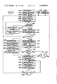
- FIG. 2 is a flow chart of a main program utilized in the control means of the invention.
- FIG. 3 is a flow chart of a "flate" sub-routine of the program
- FIG. 4 is a flow diagram of an "energize" sub-routine of the main program.
- FIG. 5 is a flow chart of a "finish" sub-routine of the main program.
- P i is initial pressure, that is, the pressure level in the tire immediately after the system is connected to the tire, usually by the valve stem, and before an inflation or deflation process is initiated.
- P c is the current pressure, that is, the pressure level in the tire at the time it is sensed during an inflation or deflation process.
- P f is the desired final pressure, that is, the desired pressure level to be present in the tire when an inflation or deflation process is concluded.
- P l is the "line" pressure, that is, a pressure level substantially equal to the pressure of a source of gas under pressure less whatever flow losses may occur during the flow of the gas from the source to the point of measurement.
- P r is a reference pressure slightly less than line pressure and which may be somewhat arbitrarily chosen. In the exemplary embodiment, P r is chosen to equal 31/32 P l .
- ⁇ P is the change in pressure from the initial pressure at any point in the inflation or deflation process, that is, P c -P i .
- the exemplary embodiment includes a conduit shown schematically at 10.
- One end 12 is adapted to be connected to a source of gas under pressure such as an air compressor shown schematically at 14.
- the other end 16 is adapted to be connected to the fill port on a tire, as for example, a typical valve stem.
- the conduit end 16 will typically be provided with a so-called air chuck by which the conduit 10 may be affixed to the tire in fluid communication with the interior therewith.
- a normally closed valve 20 Between the conduit ends 12 and 16 there is located a normally closed valve 20.
- the valve 20 When the valve 20 is closed, of course, air cannot flow from the source 14 to the tire while the converse will be true when the valve 20 is opened as will be seen. It is preferred to use a normally closed valve as the valve 20 for the reason that in the event of a malfunction in the system, the valve 20 will revert to its normally closed condition to prevent overinflation of any tire connected to the conduit end 16.
- a second valve 22 is in fluid communication with the conduit 10 downstream of the valve 20.
- the valve 22 is a normally open bleed valve for venting the conduit 10 to atmosphere to relieve pressure from the interior of a tire when it is in excess of the desired level.
- a normally opened valve is preferred, again for the reason that if there is a system malfunction, it will revert to an open condition to allow an overinflated tire to deflate.
- a pressure transducer 24 is in fluid communication with the interior of the conduit 10 between the valve 22 and the end 16 so as to sense the pressure level within the conduit at that point.
- the transducer 24 provides an electrical output signal whose magnitude is proportional to the pressure sensed.
- a normally open overpressure switch 26 (shown at the lower righthand corner of FIG. 1A).
- the purpose of the switch 26 will be described hereinafter. At present it is sufficient to note that when some particular pressure level regarded as an undesirably high level exists within the conduit 10, the switch 26 will close in response thereto to alter the operational sequence of the system.
- An information input into the system includes three thumbwheel switches 28, 30 and 32 on which the operator manually sets the hundreds, tens, and units of the desired pressure level to be placed in a tire.
- Other manual inputs include a normally open start switch 34 by which an operational sequence is initiated, and a normally open stop switch 36 by which the system may be deenergized.
- a final manual input may be provided on a switch 38.
- the switch 38 is utilized when the system is to be put into a so-called "bead-seat" mode. As is well known, when tubeless tires have just been mounted on a wheel, the tire beads will not be in abutment with the rim flanges of the wheel, but are forced to that location by elevated pressure within the tire.
- a pressure level of 40 psig within the interior of the tire will be sufficient to cause the beads to fully seat, that is, move into abutment with the rim flanges of the wheel.
- the bead seat switch 38 is utilized when such bead seating is necessary.
- the system includes three light emitting diode displays 40, 42, and 44 which indicate the hundreds, tens and units of system pressures at times monitored as will be seen.
- a second output is an audible chime 46 to provide a signal that an operational process performed by the system is complete.
- Control of inflation or deflation by the system including control of the valves, the provision of outputs, and the utilization of the inputs is attained through the use of a microprocessor 48.
- the system is powered by a power supply 50 outputed through a decade counter 52 to the microprocessor 48.
- the decade counter 52 converts the output frequency of the power supply to a suitable time base for use by the microprocessor.
- Programming instructions for the microprocessor, to be described hereinafter, are contained in a program memory or ROM 54.
- a data and address bus 56 communicates with the ROM 54 and utilizes an address latch 58 by which the address in the ROM is latched so that data may be subsequently transferred.
- Input information from the thumbwheel switches 28, 30 and 32 and output information for the LED displays 40-44 and the microprocessor 48 is controlled by a multiplexing unit 60.
- the thumbwheel switches 28-32 are also buffered at 62 into an I/O expander 64 connected to the microprocessor.
- the I/O expander 64 is utilized to enlarge the total number of system ports available to receive or transmit information due to the limited number of ports in the particular microprocessing unit utilized.
- Customary components such as decoder drivers 70 and latches 72 are utilized in connection with the LED displays 40-44 and the I/O expander while a signal conditioner 74 and an analogue to digital converter 76 are employed in connection with the transducer 24 and the microprocessor 48 to provide sensed pressure information to the latter in digital, as opposed to analogue, form.
- valves 20 and 22 are operated by outputs received from the I/O expander 64 via suitable driving circuits 78 and 80, respectively.
- valve 20 is open for predetermined periods of time, some fixed by the program, and others variable depending upon operational parameters existing in the system, to allow air from the source to flow to the interior of the tire. It will be observed that when such occurs, the application of air to the tire will be substantially at the pressure of the source. In the typical case, source pressure will be on the order of 150 psig while, in the case of a typical automobile tire, the desired pressure level will be on the order of 30 psig. Consequently, a large pressure differential will exist throughout the operational cycle and air flow will be rapid enabling rapid inflation of the tire to the desired level.
- the tire may be overinflated and in such an event, upon connection of the system thereto and operation of the system, the valve 22 will be opened as required to bleed off the excess pressure to the desired pressure level.
- the operation of the valve 22 will be automatic as determined by the system program and operational parameters.
- Very small tires such as bicycle tires represent a special case and the system includes a particular sequence which senses whether a small tire is involved and alters system operation appropriately.
- the LED displays 40-44 may be utilized to provide a simple pressure indication thereby acting as a digital pressure gauge without accompanying inflation or deflation when desired.
- the power is turned on as shown in block 100.
- a five second delay ensues to eliminate spurious signals associated with start-up.
- the next step is to initialize the various ports in the microprocessor and the I/O expander and this step is followed by a command 108 to close all system valves, that is, to close the inflate valve 20 and the bleed valve 22.
- the pressure within the tire is read by the transducer 24 as shown in block 110.
- This sampling of tire pressure will yield the pressure indication corresponding to the initial pressure in the tire.
- the same sampling procedure will yield current pressure information.
- the system then questions whether the overpressure switch 26 has been closed due to an overpressure within the tire. This decision is shown at block 112 and if it is determined that an overpressure condition exists, a loop is followed wherein the bleed valve 22 is opened as shown in block 114 and the LED display is intermittedly operated as shown at block 116 to display whatever pressure was read at block 110. The loop is continually followed until such time as the overpressure switch 26 opens indicating that the overpressure condition has been relieved. Once such has occurred, all valves are again closed as shown at block 118 and the then existent pressure within the tire is read and displayed on the LED display as shown in block 120.
- the system then questions whether or not it has received a start command from the start switch 34 as shown at block 122. If no such command has been received, the program executes a loop back to block 106 and continues to repeat the loop until a start command is received.
- the first program step is to reset and enable the interupt circuit for the stop switch 36 as shown in block 124. This is followed by a reading of the thumbwheel switches 28-32 to obtain the desired final pressure in the tire. This step is shown in block 126. The current pressure in the tire is then read as shown at block 128.
- the program proceeds to interrogate the bead seat switch 38 to determine whether the system is in the "bead-seat" mode. This interrogation is shown in block 130 and if the system is conditioned for the bead-seat mode, the next step, shown in block 132, is to display the current pressure on the LED displays 40-44. An arbitrary final pressure of 40 psig is then set as shown in block 134. This pressure level is empirically determined as it has been found that an internal pressure of 40 pounds per square inch is sufficient to drive unseated beads in any tire and wheel combination to the rim flanges of the wheel to thereby seat the beads.
- the next step is to select which valve is to be opened. This is shown in block 136 and if the pressure then existing within the tire is in excess of 40 psig, the bleed valve 22 will be selected while if the tire pressure is less than 40 psig, the inflate valve 20 will be selected.
- the system then proceeds to adjust the internal pressure to the desired pressure. Accordingly, the desired final pressure is then read from the thumbwheel switches 28-32 as shown in block 140 and the program proceeds to select which of the valves should be opened to achieve the desired pressure level as shown in block 142.
- the program proceeds to a decision shown in block 144 whereat the determination of whether the current pressure is equal to the desired final pressure is made. If the two are equal, the program returns to the initialize block 106. If not, the program proceeds to the block 142 for valve selection purposes.
- the flate routine is executed as shown at block 145.
- the flate routine may or may not include an execution of the finish routine shown in FIG. 5 and will be described in greater detail hereinafter.
- the desired final pressure in the tire will be achieved and the chime 46 will be sounded as shown at block 146.
- a two second delay ensues as shown at block 148 and then the program proceeds to execute the finish routine shown in FIG. 5 as designated by block 150.
- a decision is made at block 152 to determine whether the current pressure as sensed at the transducer 24 is equal to zero psig. If so, the system perceives this as an indication that the conduit end 16 has been disconnected from the tire (thereby allowing any pressurized gas in the conduit 10 to vent to the atmosphere through the end 16) and the program returns to the initialize block 106.
- flate in that it is capable of causing either inflation or deflation of a tire to the desired pressure level.
- the first step requires the reading and storing of the initial pressure within the tire as shown in block 160. This is accomplished by closing both of the valves 20 and 22 at the initiation of the flate routine and determining the then existent pressure within the tire by the transducer 24.
- Inquiry is then made as to whether the system is in the bead seat mode as shown at block 162. If not, a determination is made as shown at block 164 as to whether the initial pressure is within 10 psig of the desired final pressure. If it is not, the system takes this determination as an indication that a substantial inflation or deflation operation must be performed and returns to a block 166. At block 166, there is set a one second time as a control parameter and the system proceeds to execute the energize routine shown in FIG. 4.
- the program proceeds to block 168 to bypass the block 166.
- the block 168 is similar to the block 166 except that the set time is one-half of a second rather than one second.
- the energize routine proceeds for a time period as will be explained and at the conclusion thereof, the program proceeds to a block 170 which reads and displays the current pressure in the tire by means of the transducer 24 after the valves 20 and 22 have been closed.
- the program proceeds to block 172 for the purpose of determining whether the current pressure is equal to zero. This determination is made to determine whether the conduit end 16 is still connected to the tire, a zero pressure determination being an indication that disconnection, either intentional or inadvertant, has occurred.
- the program returns to its leave off point in the main program. If the current pressure is other than zero, a determination is made at the next stage of the program, block 174, as to whether the change in pressure from initial to current exceeds 20%. If so, the program splits to a block 176 which makes the determination that a small tire such as a bicycle tire is being inflated and from the block 176 proceeds to execute the finish routine shown in FIG. 5 and designated in FIG. 3 as block 178.
- the program calls for a reading and a display of the then current pressure. If the current pressure is zero, again indicating disconnection, at block 183, the program branches to return to the main program. If the pressure is not zero, at block 184, a determination is made as to whether the change in pressure exceeds 40% of that desired. If the answer is yes, the program proceeds to an initial calculation shown at block 186. If not, the program branches to a block 188 and a block 190 which repeat the steps of blocks 180 and 182.
- Equation 1 the time required to fill the tire according to Equation 1. It should be noted that the 0.9 multiplier used in Equation 1 is employed to insure that the calculated time will not exceed the actual time required in practice to achieve the desired inflation level.
- the program proceeds to a block 194 which sets a time equal to one-half of that calculated and causes the energize routine to be executed.
- the current pressure is read and displayed at block 196 and that is followed by a determination at block 198 as to whether the current pressure is equal to zero, again for determining whether disconnection has been made. Again, if yes, there is a return to the main program whereas, if no, the program proceeds to a block 200 which calls for recalculating the time required to complete inflation of the tire according to the relationship employed in Equation 1. From there, the program proceeds to block 202 which sets the time calculated and executes the energize routine.
- the purpose at block 194 of setting only one-half the time calculated versus the setting of the full time calculated at block 202 is to assure that the actual time required to attain the desired pressure level is not exceeded at the stage of the program represented by the block 194 when the inflation or deflation process will normally be further from being complete than at the time at which block 202 occurs in the process.
- the current pressure is again read and displayed at block 204 and a determination then made at block 206 as to whether the current pressure is equal to zero, again indicating a disconnection of the system from the tire. If yes, there is again a return to the main program while if not, the program proceeds to block 178 to cause execution of the finish routine. Once the finish routine is executed and completed, there will be a return to the main program as indicated in both FIGS. 3 and 5.
- the finish routine is illustrated in FIG. 5 and in addition to being always performed at the conclusion of the flate routine unless there is an earlier return to the main program due to system disconnection, can be performed independently as a step in the main program as shown at block 150 of FIG. 2 for the purposes mentioned previously.
- the first step of the finish routine is to read the thumbwheel switches 28, 30 and 32 as shown at block 210. This is followed by the step of reading and displaying the current pressure as shown in block 212. If the current pressure is equal to zero as determined by a step indicated in block 214, the routine returns to the main program again, for the purposes of indicating system disconnection.
- the routine proceeds to a block 216 whereat a determination is made as to whether the current pressure is within twenty psig of the desired final pressure. If yes, the routine proceeds to block 218 whereat a determination as to whether the current pressure is within five psig of the desired final pressure is made. Again, if the answer is yes, the routine proceeds to the block 220 to determine whether the current pressure is within two psig of the desired final pressure. If this determination is yes, the routine proceeds to a block 222 which determines whether the current pressure is equal to the final pressure. If the answer to this determination is yes, there is a return to the main program with the result that the chime 46 will ultimately be sounded to indicate the conclusion of the process.
- the program splits to a block 224 which sets up a one second time period and causes execution of the energize routine. At the conclusion of that step, the program loops back to the block 210.
- step shown in block 224 is performed. If a small tire is being inflated, the program branches to a block 226 which sets a time of one fifth of a second and executes the energize routine after which the program loops back to the block 210.
- the program branches to a block 230 again to question whether a small tire is being inflated. In this case, if the answer is no, the program proceeds to a block 232 which sets time of two fifths of a second and executes the energize routine. Upon conclusion of the energize routine, the system then loops back to the block 210. Conversely, if a small tire is being inflated, at block 230 the program branches to a block 234 which sets a time of one tenth of a second and executes the energize routine after which there is a return to the block 210.
- routine branches to the block 234 which sets a one tenth of a second time and executes the energize routine following which there is a return to the block 210.
- finish routine returns to its start whenever current pressure does not equal the final pressure, regardless of where such determination is made, it will be repetitively performed until the current pressure does equal the final pressure.
- the energize routine shown in FIG. 4 provides the actual control over the inflate valve 20 or the bleed valve 22. It utilizes, during its performance, the various times that are indicated as "set" at various stages of the flate and finish routines. However, only in the case of an inflation process is the time indicated actually used. In the case of a deflation process, the time indicated multiplied by two is utilized. This is due to the fact that the pressure differential from the source to the pressure in the tire during an inflation process will be far greater in virtually every instance than the pressure differential between the pressure in the tire and the desired final pressure during a deflation process. Consequently, because of the lesser pressure differential existing in the usual case during a deflation process, gas flow from the tire will not be as rapid and more time will be required to effect a further change in the pressure of the tire.
- the first step in the energize routine is to determine whether the bleed valve has been selected, which determination is made in either block 136 or block 142 of the main program or blocks 224, 226, 232 or 234 of the finish routine. If so, at block 242, a control parameter equal to two times the set time is introduced. If not, the set time indicated is utilized and at block 244, a timer is started to open the appropriate one of the valves 20 and 22 as shown at block 246. Following block 246, the system is then interrogated again as to whether the bleed valve has been selected as shown at block 248. If yes, the program proceeds to a block 250 for the purpose of reading the line pressure.
- the pressure in this sequence, is read via the transducer 24 with the bleed valve 22 open. Consequently, a pressure level will be sensed that will be slightly higher than atmospheric pressure unless the conduit end 16 has been disconnected from the tire in which case, atmospheric pressure will be sensed.
- the routine may branch in the event that the bleed valve 22 has not been selected. First, a determination is made at block 252 as to whether the set time for which the valve is to be opened is greater than 3/10 of a second. If the answers is no, the routine returns to block 250 and the current pressure will be read with the inflate valve 20 open. If the answer is yes, the line pressure is read at block 254, again with the inflate valve 20 open and that is followed, at block 256, by a determination of the reference pressure along with the storage of the same.
- the reference pressure determined at block 256 is selected to equal 31/32 of the line pressure and from that determination, the program returns to the block 250.
- the program proceeds to a block 262 which again questions whether the bleed valve has been selected. If so, the routine continues to a block 264 to determine whether the value in the timer, started at block 244, is equal to the time the particular valve involved is to be opened, that is, the set time in the case of the inflate valve 20 or twice the set time in the case of the bleed valve 22. If the answer is no, the program loops to return to the block 250 while if the answer is yes, the selected valve is closed at block 260.
- the program branches to a block 266 which again questions whether the time that the valve is to be opened is greater than three tenths of a second. If the answer is no, the routine returns to the block 264 for the purpose mentioned previously. If the answer is yes, the routine proceeds to a block 268 whereat the determination is made as to whether the current line pressure is less than the reference pressure determined at block 256. If yes, the valves are closed at block 260 and the routine returns to either the flate or finish routine at the point therein whereat such routines left off. Conversely, if the current line pressure is greater than the reference pressure, at block 268, the routine returns to the block 264.
- the determination made at block 268 allows the routine to be abruptly aborted in the event, for some reason, the line pressure falls below the reference pressure.
- the determinations made in blocks 252 and 266 are for the purpose of bypassing this abort mode in the event that the scheduled time for the valve to be open is less than 3/10 of a second, in which case there is insufficient time for the mechanical parts of the system to be appropriately controlled.
- the set times given in absolute terms have been empirically determined so as to provide the system with almost universal capability of controlling pressure levels in tires ranging from very small volume tires such as bicycle tires to extremely high volume tires operated at high pressures such as truck tires or even larger tires.
- desired pressure levels can be rapidly obtained hence the flate routine immediately branches to the finish routine when a determination that a small tire is connected to the system is made as the set times involved in the finish routine are small compared to those utilized at various points in the flate routine and are all that are required to rapidly inflate a small tire.
- the large times employed in the flate routine insure that a tire other than a small tire will have its internal pressure brought rapidly to a point somewhat closer to the desired pressurization level. Accurate completion of the process is then accomplished by turning to the finish routine.
- the full pressure available at the source 14 (less minor flow losses occurring in the conduit 10) is applied to the tire.
- the system provides digital control of the valves 20 and 22 as they are either opened or closed, thereby allowing unrestricted gas flow or halt it altogether. There is never a metering or throttling function performed by the valves 20 and 22 which would reduce the pressure differential involved.
- the bead-seat mode provided by the invention is a distinct advantage at tire servicing facilities that change tires in that each tire changed, or even removed from a wheel for servicing, must have its beads seated on the wheel before the wheel can be replaced on a vehicle.
- the bead-seat mode of the present invention not only insures that the beads are seated, but after that has been accomplished, automatically proceeds to set the desired pressure level within the tire without any intervention by an operator.
- the invention also automatically compensates for any leakage present at the connection between the conduit end 16 and the tire by repetitively re-executing the finish routine as required so long as the conduit 10 is connected to the tire even though the operator may neglect to make the disconnection for a sizable time period.
- Rapidity of the inflation or deflation process performed by the invention is maximized in that part of the system that calculates, based on parameters existing within the system, the time required to complete a process to thereby minimize the time spent in sampling tire pressure which of course requires closure of the valves 20 and 22 with the consequence that no inflation or deflation can occur during such sampling.
- the invention can operate as a simple pressure gauge with a digital readout. If connected to a tire, but no start command as shown in block 122 in FIG. 2 is received, the instruction at block 120 to read and display the current pressure within the tire will result in the system providing a digital pressure indication of the pressure within the tire as though it were a simple pressure gauge.
Landscapes
- Engineering & Computer Science (AREA)
- Mechanical Engineering (AREA)
- Vehicle Cleaning, Maintenance, Repair, Refitting, And Outriggers (AREA)
- Measuring Fluid Pressure (AREA)
Priority Applications (2)
| Application Number | Priority Date | Filing Date | Title |
|---|---|---|---|
| US06/247,609 US4456038A (en) | 1981-03-25 | 1981-03-25 | Apparatus for pressurizing tires to a desired level |
| JP56203319A JPS57158108A (en) | 1981-03-25 | 1981-12-15 | Device for pressurizing tire up to desired pressure level |
Applications Claiming Priority (1)
| Application Number | Priority Date | Filing Date | Title |
|---|---|---|---|
| US06/247,609 US4456038A (en) | 1981-03-25 | 1981-03-25 | Apparatus for pressurizing tires to a desired level |
Publications (1)
| Publication Number | Publication Date |
|---|---|
| US4456038A true US4456038A (en) | 1984-06-26 |
Family
ID=22935573
Family Applications (1)
| Application Number | Title | Priority Date | Filing Date |
|---|---|---|---|
| US06/247,609 Expired - Lifetime US4456038A (en) | 1981-03-25 | 1981-03-25 | Apparatus for pressurizing tires to a desired level |
Country Status (2)
| Country | Link |
|---|---|
| US (1) | US4456038A (de) |
| JP (1) | JPS57158108A (de) |
Cited By (42)
| Publication number | Priority date | Publication date | Assignee | Title |
|---|---|---|---|---|
| US4510979A (en) * | 1982-05-24 | 1985-04-16 | Hjorth Hansen Arne | Apparatus for controlling the inflation of tires |
| US4583566A (en) * | 1983-08-16 | 1986-04-22 | Kalavitz Paul V | Pressure control system |
| FR2584347A1 (fr) * | 1985-07-04 | 1987-01-09 | Houbre Maurice | Procede de gonflage automatique de pneumatiques et dispositif pour sa mise en oeuvre |
| US4640331A (en) * | 1984-06-04 | 1987-02-03 | Eaton Corporation | Central tire inflation system |
| EP0133482A3 (en) * | 1983-08-05 | 1987-05-06 | Mahle Gmbh | Method for regulating a tyre inflating device |
| US4687014A (en) * | 1984-08-17 | 1987-08-18 | Godal Egil O | Method and apparatus for reducing the response time of remotely controlled, hydraulic control systems |
| US4696334A (en) * | 1985-02-18 | 1987-09-29 | Precision Mecanique Labinal | Deflating device for pneumatic tires of vehicles |
| US4763709A (en) * | 1986-07-03 | 1988-08-16 | Teledyne Industries Inc. | Tire inflation system |
| US4782878A (en) * | 1986-12-18 | 1988-11-08 | Tire Inflation Systems, Corp. | Tire inflating and deflating system and apparatus |
| US4782879A (en) * | 1985-10-04 | 1988-11-08 | Precision Mecanique Labinal | Hydraulic or pneumatic pressure control device and its application in devices regulating the pressure of tires of vehicles in motion |
| US4850402A (en) * | 1987-10-28 | 1989-07-25 | Hennessy Industries, Inc. | System for controlling the inflation of tires |
| US4862938A (en) * | 1986-12-18 | 1989-09-05 | Tire Inflation Systems Corp. | Vehicular tire dump valve and pressurization system |
| US4869306A (en) * | 1987-12-04 | 1989-09-26 | Keys Kenneth B | Air inlet and automatic pressure adjustment device for a tire |
| US4905742A (en) * | 1989-02-27 | 1990-03-06 | Bruno Wessel Limited | Pneumatic safety circuit for air inflation devices |
| GB2250061A (en) * | 1990-11-13 | 1992-05-27 | Jose Edmans Forti | Setting tyre pressures |
| EP0542728A1 (de) | 1988-07-25 | 1993-05-19 | Eaton Corporation | Luftabfuhr-Kontrollsystem und Verfahren |
| US5249609A (en) * | 1988-07-25 | 1993-10-05 | Eaton Corporation | Deflation control system and method |
| EP0590462A1 (de) * | 1992-09-28 | 1994-04-06 | Fujikura Ltd. | Reifen-Druckregelvorrichtung für Kraftfahrzeuge |
| US5540268A (en) * | 1991-12-17 | 1996-07-30 | Mittal; Chander | Apparatus for repeatable adjustment of tire pressure |
| WO1996041244A1 (en) * | 1995-06-07 | 1996-12-19 | The Curators Of The University Of Missouri | Pressure/vacuum regulator |
| US5617898A (en) * | 1991-09-10 | 1997-04-08 | Smc Kabushiki Kaisha | Fluid pressure apparatus |
| US5621398A (en) * | 1995-08-07 | 1997-04-15 | Saint Switch, Inc. | Programmable switch |
| GB2323453A (en) * | 1997-03-21 | 1998-09-23 | Andre Alan Donald King | Apparatus for inflating vehicle tyre incorporating set pressure reading device |
| GB2328036A (en) * | 1997-08-05 | 1999-02-10 | John Daniel Davies | Electronic tyre inflator |
| US6021799A (en) * | 1994-03-03 | 2000-02-08 | Nordson Corporation | Air regulator control system for powder coating operation |
| US6385554B1 (en) * | 1999-11-02 | 2002-05-07 | Leo Wu | Digital tire gauge with visual and voice response system |
| US6532796B1 (en) | 1997-02-21 | 2003-03-18 | Anelva Corporation | Method of substrate temperature control and method of assessing substrate temperature controllability |
| US6894607B1 (en) * | 2001-12-03 | 2005-05-17 | Dana Corporation | Tire pressure management system valve integrity verification method |
| US20060002800A1 (en) * | 2004-06-30 | 2006-01-05 | Klein Christopher D | Compressor control apparatus |
| US20060169327A1 (en) * | 2004-03-09 | 2006-08-03 | Mks Instruments, Inc. | Pressure regulation in remote zones |
| US20080275605A1 (en) * | 2007-05-01 | 2008-11-06 | Murphy Jeffrey B | Method and apparatus for monitoring the status of automotive service equipment and signaling the status by a wireless technology to the operator |
| US20090260710A1 (en) * | 2008-04-21 | 2009-10-22 | Lydi, Llc | Automated apparatus and method for tire pressure maintenance |
| US7789112B1 (en) * | 2006-11-09 | 2010-09-07 | Wise Robert W | Method and system for inflating an inflatable object |
| US20110100480A1 (en) * | 2009-10-29 | 2011-05-05 | Raymond Huang | Mobile tire inflator |
| US20110101010A1 (en) * | 2009-10-30 | 2011-05-05 | Maiocco Mark A | Tilting rack system |
| US7975731B2 (en) | 2007-05-01 | 2011-07-12 | Rti Technologies, Inc. | Method and apparatus for evacuating and filling tires with high purity nitrogen |
| US20110265894A1 (en) * | 2010-04-30 | 2011-11-03 | Kanjun Yamamoto | Apparatus for controlling internal pressure of hermetically sealed chamber |
| USD834070S1 (en) | 2017-12-12 | 2018-11-20 | Milwaukee Electric Tool Corporation | Inflator |
| EP3434539A1 (de) * | 2017-07-27 | 2019-01-30 | Robert Bosch GmbH | Verfahren und vorrichtung zur identifikation eines reifentyps an einem fahrzeug |
| US10496112B2 (en) * | 2016-12-26 | 2019-12-03 | Shimadzu Corporation | Valve device |
| US10974701B2 (en) | 2018-02-28 | 2021-04-13 | Milwaukee Electric Tool Corporation | Inflator with dynamic pressure compensation |
| US11320843B2 (en) * | 2019-10-17 | 2022-05-03 | Dongguan Hesheng Machinery & Electric Co., Ltd. | Air compression system with pressure detection |
Families Citing this family (4)
| Publication number | Priority date | Publication date | Assignee | Title |
|---|---|---|---|---|
| JPS60128007A (ja) * | 1983-12-14 | 1985-07-08 | Onodani Kiko Kk | 自動空気圧充填装置 |
| JPH0592473U (ja) * | 1992-05-20 | 1993-12-17 | 川崎重工業株式会社 | 汎用エンジンの電装ケーブルクランプ機構 |
| JP2000118364A (ja) * | 1998-10-14 | 2000-04-25 | Bridgestone Corp | 大型タイヤにn2ガスを充填するための方法 |
| ES3055309T3 (en) * | 2016-12-15 | 2026-02-11 | Active Tools Int Hk Ltd | Tire maintenance means |
Citations (3)
| Publication number | Priority date | Publication date | Assignee | Title |
|---|---|---|---|---|
| EP0019463A2 (de) * | 1979-05-18 | 1980-11-26 | John Sansbury Knubley | Luftverteilungsanlage |
| US4241750A (en) * | 1978-11-27 | 1980-12-30 | Kabushiki Kaisha Cosmo Keiki | Pressure setting device |
| US4253480A (en) * | 1978-03-16 | 1981-03-03 | Knorr-Bremse Gmbh | Pressure regulator for fluid pressures |
Family Cites Families (1)
| Publication number | Priority date | Publication date | Assignee | Title |
|---|---|---|---|---|
| JPS5031439A (de) * | 1973-07-23 | 1975-03-27 |
-
1981
- 1981-03-25 US US06/247,609 patent/US4456038A/en not_active Expired - Lifetime
- 1981-12-15 JP JP56203319A patent/JPS57158108A/ja active Granted
Patent Citations (4)
| Publication number | Priority date | Publication date | Assignee | Title |
|---|---|---|---|---|
| US4253480A (en) * | 1978-03-16 | 1981-03-03 | Knorr-Bremse Gmbh | Pressure regulator for fluid pressures |
| US4241750A (en) * | 1978-11-27 | 1980-12-30 | Kabushiki Kaisha Cosmo Keiki | Pressure setting device |
| EP0019463A2 (de) * | 1979-05-18 | 1980-11-26 | John Sansbury Knubley | Luftverteilungsanlage |
| US4333491A (en) * | 1979-05-18 | 1982-06-08 | Knubley John S | Air dispensing apparatus |
Cited By (62)
| Publication number | Priority date | Publication date | Assignee | Title |
|---|---|---|---|---|
| US4510979A (en) * | 1982-05-24 | 1985-04-16 | Hjorth Hansen Arne | Apparatus for controlling the inflation of tires |
| EP0133482A3 (en) * | 1983-08-05 | 1987-05-06 | Mahle Gmbh | Method for regulating a tyre inflating device |
| US4583566A (en) * | 1983-08-16 | 1986-04-22 | Kalavitz Paul V | Pressure control system |
| US4640331A (en) * | 1984-06-04 | 1987-02-03 | Eaton Corporation | Central tire inflation system |
| US4687014A (en) * | 1984-08-17 | 1987-08-18 | Godal Egil O | Method and apparatus for reducing the response time of remotely controlled, hydraulic control systems |
| US4696334A (en) * | 1985-02-18 | 1987-09-29 | Precision Mecanique Labinal | Deflating device for pneumatic tires of vehicles |
| FR2584347A1 (fr) * | 1985-07-04 | 1987-01-09 | Houbre Maurice | Procede de gonflage automatique de pneumatiques et dispositif pour sa mise en oeuvre |
| US4782879A (en) * | 1985-10-04 | 1988-11-08 | Precision Mecanique Labinal | Hydraulic or pneumatic pressure control device and its application in devices regulating the pressure of tires of vehicles in motion |
| US4763709A (en) * | 1986-07-03 | 1988-08-16 | Teledyne Industries Inc. | Tire inflation system |
| US4782878A (en) * | 1986-12-18 | 1988-11-08 | Tire Inflation Systems, Corp. | Tire inflating and deflating system and apparatus |
| US4862938A (en) * | 1986-12-18 | 1989-09-05 | Tire Inflation Systems Corp. | Vehicular tire dump valve and pressurization system |
| US4850402A (en) * | 1987-10-28 | 1989-07-25 | Hennessy Industries, Inc. | System for controlling the inflation of tires |
| US4869306A (en) * | 1987-12-04 | 1989-09-26 | Keys Kenneth B | Air inlet and automatic pressure adjustment device for a tire |
| EP0542728A1 (de) | 1988-07-25 | 1993-05-19 | Eaton Corporation | Luftabfuhr-Kontrollsystem und Verfahren |
| US5249609A (en) * | 1988-07-25 | 1993-10-05 | Eaton Corporation | Deflation control system and method |
| US5409045A (en) * | 1988-07-25 | 1995-04-25 | Eaton Corporation | Deflating control system and method |
| US4905742A (en) * | 1989-02-27 | 1990-03-06 | Bruno Wessel Limited | Pneumatic safety circuit for air inflation devices |
| GB2250061A (en) * | 1990-11-13 | 1992-05-27 | Jose Edmans Forti | Setting tyre pressures |
| US5617898A (en) * | 1991-09-10 | 1997-04-08 | Smc Kabushiki Kaisha | Fluid pressure apparatus |
| US5884664A (en) * | 1991-09-10 | 1999-03-23 | Smc Kabushiki Kaisha | Fluid pressure apparatus |
| US5540268A (en) * | 1991-12-17 | 1996-07-30 | Mittal; Chander | Apparatus for repeatable adjustment of tire pressure |
| EP0590462A1 (de) * | 1992-09-28 | 1994-04-06 | Fujikura Ltd. | Reifen-Druckregelvorrichtung für Kraftfahrzeuge |
| US5429166A (en) * | 1992-09-28 | 1995-07-04 | Fujikura Ltd. | Apparatus for regulating the pneumatic pressure of a motor vehicle tire |
| AU667123B2 (en) * | 1992-09-28 | 1996-03-07 | Fujikura Ltd. | Apparatus for regulating the pneumatic pressure of a motor vehicle tire |
| US6021799A (en) * | 1994-03-03 | 2000-02-08 | Nordson Corporation | Air regulator control system for powder coating operation |
| US5813426A (en) * | 1995-06-07 | 1998-09-29 | University Of Missouri | Vacuum regulator |
| US5613514A (en) * | 1995-06-07 | 1997-03-25 | The Curators Of The University Of Missouri | Pressure/vacuum regulator |
| WO1996041244A1 (en) * | 1995-06-07 | 1996-12-19 | The Curators Of The University Of Missouri | Pressure/vacuum regulator |
| US5621398A (en) * | 1995-08-07 | 1997-04-15 | Saint Switch, Inc. | Programmable switch |
| US6532796B1 (en) | 1997-02-21 | 2003-03-18 | Anelva Corporation | Method of substrate temperature control and method of assessing substrate temperature controllability |
| GB2323453A (en) * | 1997-03-21 | 1998-09-23 | Andre Alan Donald King | Apparatus for inflating vehicle tyre incorporating set pressure reading device |
| GB2328036A (en) * | 1997-08-05 | 1999-02-10 | John Daniel Davies | Electronic tyre inflator |
| US6385554B1 (en) * | 1999-11-02 | 2002-05-07 | Leo Wu | Digital tire gauge with visual and voice response system |
| US6894607B1 (en) * | 2001-12-03 | 2005-05-17 | Dana Corporation | Tire pressure management system valve integrity verification method |
| US20060007007A1 (en) * | 2001-12-03 | 2006-01-12 | Claussen Stephen P | Tire pressure management system valve integrity verification method |
| US7265659B2 (en) | 2001-12-03 | 2007-09-04 | Dana Corporation | Tire pressure management system valve integrity verification method |
| US20070290826A1 (en) * | 2001-12-03 | 2007-12-20 | Claussen Stephen P | Tire pressure management system valve integrity verification method |
| US7538661B2 (en) | 2001-12-03 | 2009-05-26 | Dana Heavy Vehicle Systems Group, Llc | Tire pressure management system valve integrity verification method |
| US20060169327A1 (en) * | 2004-03-09 | 2006-08-03 | Mks Instruments, Inc. | Pressure regulation in remote zones |
| US8689822B2 (en) | 2004-03-09 | 2014-04-08 | Mks Instruments, Inc. | Pressure regulation in remote zones |
| US8037896B2 (en) * | 2004-03-09 | 2011-10-18 | Mks Instruments, Inc. | Pressure regulation in remote zones |
| US20060002800A1 (en) * | 2004-06-30 | 2006-01-05 | Klein Christopher D | Compressor control apparatus |
| US7556478B2 (en) | 2004-06-30 | 2009-07-07 | Campbell Hausfeld/Scott Fetzer Company | Compressor control apparatus |
| US7789112B1 (en) * | 2006-11-09 | 2010-09-07 | Wise Robert W | Method and system for inflating an inflatable object |
| US7778751B2 (en) | 2007-05-01 | 2010-08-17 | Rti Technologies, Inc. | Method and apparatus for monitoring the status of automotive service equipment and signaling the status by a wireless technology to the operator |
| US7975731B2 (en) | 2007-05-01 | 2011-07-12 | Rti Technologies, Inc. | Method and apparatus for evacuating and filling tires with high purity nitrogen |
| US20080275605A1 (en) * | 2007-05-01 | 2008-11-06 | Murphy Jeffrey B | Method and apparatus for monitoring the status of automotive service equipment and signaling the status by a wireless technology to the operator |
| US20090260710A1 (en) * | 2008-04-21 | 2009-10-22 | Lydi, Llc | Automated apparatus and method for tire pressure maintenance |
| US8191586B2 (en) | 2008-04-21 | 2012-06-05 | Lydi, Llc | Automated apparatus and method for tire pressure maintenance |
| US20110100480A1 (en) * | 2009-10-29 | 2011-05-05 | Raymond Huang | Mobile tire inflator |
| US8418713B2 (en) * | 2009-10-29 | 2013-04-16 | Raymond Huang | Mobile tire inflator |
| US20110101010A1 (en) * | 2009-10-30 | 2011-05-05 | Maiocco Mark A | Tilting rack system |
| US8365758B2 (en) * | 2009-10-30 | 2013-02-05 | Angels' Share Innovations, LLC. | Beverage barrel bladder system and apparatus |
| US8453671B2 (en) * | 2010-04-30 | 2013-06-04 | Shibuya Kogyo Co., Ltd. | Apparatus for controlling internal pressure of hermetically sealed chamber |
| US20110265894A1 (en) * | 2010-04-30 | 2011-11-03 | Kanjun Yamamoto | Apparatus for controlling internal pressure of hermetically sealed chamber |
| US10496112B2 (en) * | 2016-12-26 | 2019-12-03 | Shimadzu Corporation | Valve device |
| EP3434539A1 (de) * | 2017-07-27 | 2019-01-30 | Robert Bosch GmbH | Verfahren und vorrichtung zur identifikation eines reifentyps an einem fahrzeug |
| USD834070S1 (en) | 2017-12-12 | 2018-11-20 | Milwaukee Electric Tool Corporation | Inflator |
| US10974701B2 (en) | 2018-02-28 | 2021-04-13 | Milwaukee Electric Tool Corporation | Inflator with dynamic pressure compensation |
| US20210206353A1 (en) * | 2018-02-28 | 2021-07-08 | Milwaukee Electric Tool Corporation | Inflator with dynamic pressure compensation |
| US11679744B2 (en) | 2018-02-28 | 2023-06-20 | Milwaukee Electric Tool Corporation | Inflator with dynamic pressure compensation |
| US11320843B2 (en) * | 2019-10-17 | 2022-05-03 | Dongguan Hesheng Machinery & Electric Co., Ltd. | Air compression system with pressure detection |
Also Published As
| Publication number | Publication date |
|---|---|
| JPS57158108A (en) | 1982-09-29 |
| JPS6220928B2 (de) | 1987-05-09 |
Similar Documents
| Publication | Publication Date | Title |
|---|---|---|
| US4456038A (en) | Apparatus for pressurizing tires to a desired level | |
| US5891277A (en) | Automotive tire inflation system | |
| US5611875A (en) | Automotive tire inflation system | |
| US4702287A (en) | Method and apparatus for controlling the automatic inflation of tires for testing | |
| CA2483029C (en) | Active adaptation of control algorithms for a central tire inflation system | |
| US6293147B1 (en) | Wheel balancer with pressure adjustment | |
| US5629873A (en) | Distributed intelligence vehicular tire air pressurization system and method | |
| CA2473965C (en) | Tire pressure monitoring method | |
| US5035274A (en) | Wheel/tire inflator | |
| US5629874A (en) | Vehicular tire air pressurization system and method | |
| EP1453689B1 (de) | Lernverfahren des solldrucks zur druckregelung | |
| US5429166A (en) | Apparatus for regulating the pneumatic pressure of a motor vehicle tire | |
| US9694630B2 (en) | Method of determining tire pressure | |
| US5256348A (en) | Tire shaping pressure control system and method | |
| KR900017817A (ko) | 중앙타이어 팽창장치용 타이어 누출 검출방법 | |
| JPS5953260A (ja) | 空気圧タイヤ膨らまし装置 | |
| US20250214546A1 (en) | Method for pressure measurement duringtire inflation, automatic inflation method, and tire inflation pump | |
| KR102817102B1 (ko) | 화차용 디지털식 단차 제동 시험기 | |
| JPH0376260B2 (de) | ||
| KR100527831B1 (ko) | 타이어 공기누출 가속 측정장치 | |
| TR2025016351U5 (tr) | BİR ARAÇ LASTİK BASINCININ OTOMATİK OLARAK ŞİŞİRİLMESİ VE AYARLANMASINA İLİŞKİN MEKATRONİK CİHAZ ve YÖNTEM | |
| EP0283076A1 (de) | Vorrichtung zum Aufpumpen von Autoreifen | |
| JPS60107407A (ja) | 車高調整装置の圧力デ−タ処理方法 |
Legal Events
| Date | Code | Title | Description |
|---|---|---|---|
| AS | Assignment |
Owner name: HENNESSY INDUSTRIES, INC., A CORP. OF DE. Free format text: ASSIGNMENT OF ASSIGNORS INTEREST.;ASSIGNORS:GWALTNEY ROBERT E.;HOLLADAY JIM L.;REEL/FRAME:003864/0597 Effective date: 19810319 |
|
| STCF | Information on status: patent grant |
Free format text: PATENTED CASE |
|
| FEPP | Fee payment procedure |
Free format text: PAYOR NUMBER ASSIGNED (ORIGINAL EVENT CODE: ASPN); ENTITY STATUS OF PATENT OWNER: LARGE ENTITY |
|
| FEPP | Fee payment procedure |
Free format text: PAYER NUMBER DE-ASSIGNED (ORIGINAL EVENT CODE: RMPN); ENTITY STATUS OF PATENT OWNER: LARGE ENTITY Free format text: PAYOR NUMBER ASSIGNED (ORIGINAL EVENT CODE: ASPN); ENTITY STATUS OF PATENT OWNER: LARGE ENTITY |
|
| FEPP | Fee payment procedure |
Free format text: PAYOR NUMBER ASSIGNED (ORIGINAL EVENT CODE: ASPN); ENTITY STATUS OF PATENT OWNER: LARGE ENTITY Free format text: PAYER NUMBER DE-ASSIGNED (ORIGINAL EVENT CODE: RMPN); ENTITY STATUS OF PATENT OWNER: LARGE ENTITY |
|
| AS | Assignment |
Owner name: CGG HOLDINGS CORP. Free format text: MORTGAGE;ASSIGNOR:HENNESSY INDUSTRIES, INC., A DE. CORP.;REEL/FRAME:004690/0167 Effective date: 19861230 |
|
| FPAY | Fee payment |
Year of fee payment: 4 |
|
| AS | Assignment |
Owner name: HENNESSY TECHNOLOGY CORPORATION, DELAWARE Free format text: ASSIGNMENT OF ASSIGNORS INTEREST.;ASSIGNOR:HENNESSY CORPORATION;REEL/FRAME:005234/0033 Effective date: 19881221 |
|
| FEPP | Fee payment procedure |
Free format text: PAYOR NUMBER ASSIGNED (ORIGINAL EVENT CODE: ASPN); ENTITY STATUS OF PATENT OWNER: LARGE ENTITY Free format text: PAYER NUMBER DE-ASSIGNED (ORIGINAL EVENT CODE: RMPN); ENTITY STATUS OF PATENT OWNER: LARGE ENTITY |
|
| FPAY | Fee payment |
Year of fee payment: 8 |
|
| REMI | Maintenance fee reminder mailed | ||
| AS | Assignment |
Owner name: SERVICE STATION PRODUCTS COMPANY, DELAWARE Free format text: CHANGE OF NAME;ASSIGNOR:HENNESSEY TECHNOLOGY CORPORATION;REEL/FRAME:007268/0028 Effective date: 19931214 |
|
| FPAY | Fee payment |
Year of fee payment: 12 |