US4495796A - Apparatus and method for measuring permeability of a moving web - Google Patents
Apparatus and method for measuring permeability of a moving web Download PDFInfo
- Publication number
- US4495796A US4495796A US06/436,239 US43623982A US4495796A US 4495796 A US4495796 A US 4495796A US 43623982 A US43623982 A US 43623982A US 4495796 A US4495796 A US 4495796A
- Authority
- US
- United States
- Prior art keywords
- web
- permeability
- head
- sensing
- traversing
- Prior art date
- Legal status (The legal status is an assumption and is not a legal conclusion. Google has not performed a legal analysis and makes no representation as to the accuracy of the status listed.)
- Expired - Fee Related
Links
- 230000035699 permeability Effects 0.000 title claims abstract description 60
- 238000000034 method Methods 0.000 title claims abstract description 23
- 239000012530 fluid Substances 0.000 claims abstract description 19
- 230000001939 inductive effect Effects 0.000 claims abstract 2
- 238000005259 measurement Methods 0.000 claims description 30
- 238000010926 purge Methods 0.000 claims description 8
- 239000000428 dust Substances 0.000 claims description 5
- 238000009530 blood pressure measurement Methods 0.000 claims description 3
- 238000004364 calculation method Methods 0.000 claims description 2
- 235000019504 cigarettes Nutrition 0.000 abstract description 19
- 238000012544 monitoring process Methods 0.000 description 20
- 238000004519 manufacturing process Methods 0.000 description 8
- 239000000047 product Substances 0.000 description 8
- 241000208125 Nicotiana Species 0.000 description 6
- 235000002637 Nicotiana tabacum Nutrition 0.000 description 6
- 238000004458 analytical method Methods 0.000 description 3
- 230000008859 change Effects 0.000 description 3
- 238000012806 monitoring device Methods 0.000 description 3
- 230000008569 process Effects 0.000 description 3
- 230000004044 response Effects 0.000 description 3
- 230000001960 triggered effect Effects 0.000 description 3
- 238000011144 upstream manufacturing Methods 0.000 description 3
- 230000009471 action Effects 0.000 description 2
- 238000013459 approach Methods 0.000 description 2
- 239000012895 dilution Substances 0.000 description 2
- 238000010790 dilution Methods 0.000 description 2
- 238000009826 distribution Methods 0.000 description 2
- 239000000463 material Substances 0.000 description 2
- 230000007246 mechanism Effects 0.000 description 2
- 230000004048 modification Effects 0.000 description 2
- 238000012986 modification Methods 0.000 description 2
- 238000012545 processing Methods 0.000 description 2
- 230000001105 regulatory effect Effects 0.000 description 2
- 230000006978 adaptation Effects 0.000 description 1
- 230000008901 benefit Effects 0.000 description 1
- 230000015572 biosynthetic process Effects 0.000 description 1
- 238000007664 blowing Methods 0.000 description 1
- 239000003990 capacitor Substances 0.000 description 1
- 239000007795 chemical reaction product Substances 0.000 description 1
- 238000010276 construction Methods 0.000 description 1
- 230000001276 controlling effect Effects 0.000 description 1
- 230000008878 coupling Effects 0.000 description 1
- 238000010168 coupling process Methods 0.000 description 1
- 238000005859 coupling reaction Methods 0.000 description 1
- 125000004122 cyclic group Chemical group 0.000 description 1
- 238000013461 design Methods 0.000 description 1
- 238000001514 detection method Methods 0.000 description 1
- 238000007599 discharging Methods 0.000 description 1
- 239000011799 hole material Substances 0.000 description 1
- 230000000977 initiatory effect Effects 0.000 description 1
- 230000003993 interaction Effects 0.000 description 1
- 238000003754 machining Methods 0.000 description 1
- 230000007257 malfunction Effects 0.000 description 1
- 239000011159 matrix material Substances 0.000 description 1
- 238000000691 measurement method Methods 0.000 description 1
- 238000009877 rendering Methods 0.000 description 1
- 238000005070 sampling Methods 0.000 description 1
- 239000000243 solution Substances 0.000 description 1
- 229910001220 stainless steel Inorganic materials 0.000 description 1
- 239000010935 stainless steel Substances 0.000 description 1
- 238000012360 testing method Methods 0.000 description 1
- 230000000007 visual effect Effects 0.000 description 1
- 239000011800 void material Substances 0.000 description 1
Images


Classifications
-
- G—PHYSICS
- G01—MEASURING; TESTING
- G01N—INVESTIGATING OR ANALYSING MATERIALS BY DETERMINING THEIR CHEMICAL OR PHYSICAL PROPERTIES
- G01N15/00—Investigating characteristics of particles; Investigating permeability, pore-volume or surface-area of porous materials
- G01N15/08—Investigating permeability, pore-volume, or surface area of porous materials
- G01N15/082—Investigating permeability by forcing a fluid through a sample
- G01N15/0826—Investigating permeability by forcing a fluid through a sample and measuring fluid flow rate, i.e. permeation rate or pressure change
Definitions
- This invention relates to measurement apparatus and methods, and more particularly to apparatus and methods for measuring permeability of cigarette papers in terms of CORESTA units.
- CORESTA unit a standard unit of measurement
- any successful online monitoring device must be capable of dealing with wide, rapid swings in permeability.
- Ziegenhagen assumes that a given change in flow always results in the same change in pressure; as Graham shows, this supposition simply is not true. If permeability variations are sufficiently small that the relation approximates linearity, or if accuracy requirements are not high, the device may still serve. In the cigarette industry, however, paper permeability will vary greatly, and a high degree of accuracy must be maintained.
- a disclosure by Brown, U.S. Pat. No. 4,253,010 is a reference-type permeabilty detector and control system.
- a vacuum source regulated for constant flow, is connected to sensing means at two points, a reference point and a sample point.
- a U-shaped manometer tube is located between these vacuum lines, so that when the sensed permeabilty at the two points is equal, the vacuum line pressures are equal, causing the fluid in each leg of the U to be at the same level. Differences in permeability, and hence pressure, cause one leg or the other of the U to be at a higher level than the other, which condition is sensed by photoelectric means.
- This disclosure is incapable of solving the problem of accurate, direct readout of CORESTA permeabilty.
- this is a reference-type monitor, not adapted to provide output in terms of the CORESA permeability.
- this disclosure shares with the patents discussed above the inherent inaccuracies of a constant-flow regulated system.
- detection of pressure differentials by means of a fluid manometer cannot respond to rapid variations in pressure.
- the mass of the fluid possesses sufficient inertia to damp out rapid variations, allowing measurement only of average, rather than instantaneous, values.
- a further object of this invention is to provide a method and apparatus for the on-line measurement of the permeability, in CORESTA units, of a moving web of paper used in cigarette making.
- Another object of this invention is to enable a machine operator to monitor the permeability of a continuous moving web in terms of both average values and the range of values sensed.
- Another object of this invention is to provide apparatus capable of monitoring the permeability of a wide variety of paper products used in the tobacco industry.
- the present invention includes means for monitoring the permeability of a continuous moving web at sequential locations on the web.
- Control means responsive to a cam and cam roller, cause the head to traverse from an initial position, dwell in subsequent monitoring positions, and return to the initial position.
- the head and associated vacuum lines are purged of accumulated dust by a pulse of compressed air.
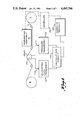
- FIG. 1 is a schematic of the present invention
- FIG. 2 is a detailed schematic of pneumatic and electronic measurement systems
- FIG. 3 is a schematic of a calculating circuit
- FIG. 4 is a perspective of a traversing head apparatus
- FIG. 5 is a side view of the traversing head apparatus
- FIG. 6 is a detailed perspective of a pressure sensing head
- FIG. 7 is a side view of the pressure sensing head, partially broken away to show internal construction
- FIG. 8 is a schematic representation of the cyclic motion of the traversing head apparatus.
- V A(PD) N
- V volumetric flow rate
- PD pressure drop
- a and N constants which vary from paper to paper.
- FIG. 1 Apparatus to accomplish this result is shown in general schematic form in FIG. 1.
- a permeable web 3 is fed from a feedroll 2, across a sensing head 100, to a take-up roll 6, which is driven by a power source (not shown).
- a perforating assembly 4 is located upstream of the pressure sensing head. This assembly is necessary if the permeable web consists of cigarette tipping paper but is of course not necessary if other materials, such as tobacco rod wrapper, were to be monitored.
- a fluid flow is established across the web, into sensing head 100, and through pneumatic line 110. Two independent measurement systems draw data from the sensing head.
- Pneumatic line 110 feeds a volumetric flow measurement system 10 which measures volumetric fluid flow and converts that measurement into an electrical signal.
- a separate pneumatic line 111 feeds a pressure measurement system 20 which measures pressure drop across the web and converts that value into an electrical signal. Both signals are fed to a calculating circuit 120, which performs the mathematical operations required to convert measured values into a CORESTA value, and feeds that result to a CORESTA readout system 130. If direct feedback control of, for example, a perforating assembly, is desired, a controller 140, of a type known to the art, could be added to the system to provide such control.
- FIG. 2 A detailed schematic of the measurement and readout systems is shown in FIG. 2.
- airflow is established by a vacuum source 12, within parameters set by a vacuum regulator 14 and metering valve 16.
- a vacuum source 12 within parameters set by a vacuum regulator 14 and metering valve 16.
- volumetric flow is measured in a laminar flow element 18.
- the fluid stream is directed through a matrix of minute parallel capillary passages whose cross section is sufficiently small to produce laminar flow from the normally occurring turbulent flow of the fluid stream.
- volumetric flow rate is directly proportional to pressure drop, permitting direct, accurate measurement of volumetric flow.
- a suitable laminar flow element was found to be Model 50MJ10, manufactured by Meriam Instrument Division of Scott & Fetzer, 10920 Madison Ave., Cleveland, Ohio, 44102.
- the pressure drop across the laminar flow element is obtained by coupling the element's inlet and outlet pressure sensing ports, P L1 and P L2 , to the ports of a transducer 24 by pneumatic lines 17 and 19.
- the transducer converts the existing pressures to an electrical signal which, after demodulation in demodulator 26, corresponds to the measured volumetric flow rate, V M .
- a suitable transducer and demodulator are Validyne models DP-15 and CD-101, respectively, produced by Validyne Engineering Corp., 8626 Wilbur Avenue, Northridge, Calif. 91324.
- a purge valve 11 Directly upstream of the laminar flow element is a purge valve 11.
- This valve is a three-way device, whose normally-open ports are connected to the laminar flow element 18 and the vacuum line 110.
- the normally-closed port is connected to a compressed air source 21.
- This port is actuated by a solenoid responsive to a signal from the control system, as hereinafter explained.
- the solenoid When the solenoid is actuated, the compressed air source is connected to vacuum line 110 and the volumetric measurement system 10 is disconnected.
- a filter 22 is located upstream of the purge valve and communicates directly with the pressure sensing head 100 by vacuum line 110. Both the filter and the purge valve may be selected from readily available components.
- the pressure measurement system 20 communicates with the pressure sensing head via vacuum line 111.
- the pressure drop within the head is converted to an electrical signal by transducer 32, feeding demodulator 34.
- This signal is referenced to atmospheric pressure by leaving one of the transducer ports open to atmospheric pressure, P A .
- the demodulator output signal corresponds to the measured pressure drop, PD M .
- Suitable components for this transducer and demodulator are identical to those listed above.
- the value of the exponential constant N is experimentally determined for a given product and then set into the calculating circuit 120. As mentioned above, it is known that this constant also varies with changes in PD M . We have discovered, however, that variations on the order of 10-20% do not sufficiently affect the value of N to render permeability measurements unacceptably inaccurate. We therefore provide an out-of-range indicator 40 to insure that the average pressure in the system stays within this operating range. That result is achieved by connecting two comparators 42 and 46 in parallel with the pressure drop signal demodulator 34 output.
- the trigger points of these comparators are chosen such that one comparator triggers when the demodulator output falls below a preselected value corresponding to the low end of the operating range, and the other triggers when the demodulator output exceeds an upper limit.
- the comparator outputs are connected to lamps or LED's 43 and 45 to give the machine operator a visual indication of an out-of-range condition. The operator can then adjust metering valve 16 to bring the average pressure within operational limits.
- Typical components for comparators 42 and 46 are Texas Instruments Type 339 comparators, readily available to the art. Resistive networks are chosen such that the lower limit comparator triggers at a signal corresponding to a pressure drop of 0.8 centibars, and the upper limit comparator triggers at values in excess of 1.2 centibars.
- a vacuum source 12 establishes fluid flow through the volumetric flow system 10, vacuum line 110, sensing head 100, and across the web 3.
- a metering valve 16 and vacuum regulator 14 cooperate to maintain pressure in this line at about 1.0 centibar.
- Pressure drop across a laminar flow element 18 is converted to an electrical signal analogous to the measured volumetric flow rate, V M by transducer 24 and demodulator 26.
- the exact pressure drop at the sensing head 100 is converted into an electrical signal corresponding to the measured pressure drop, PD M by transducer 32 and demodulator 34.
- An out-of-range indicator 40 insures that the system pressure remains within operating limits.
- the control system actuates the purge valve 20 solenoid, disconnecting the vacuum line 110 from the laminar flow element 18 and connecting it to a compressed air source 21. Compressed air then flows through the filter 22 and vacuum line 110, and out the monitoring head 100, discharging any dust which may have accumulated therein. Subsequently, the solenoid is deactivated and the vacuum line reconnected to the laminar flow element.
- the signals V M and PD M are processed in the calculating circuit 120 to produce the CORESTA readout signal V S , as shown in the schematic of FIG. 3.
- Mathematical processing takes place in a programmable multi-function module 122. Resistive values and pin connections shown correspond to those employed on Analog Devices model 433J, available from that company at Route 1, Industrial Park, Norwood, Mass., 02062. Signals PD M and V M are input through module pins 9 and 10 respectively.
- the potentiometer 129 connected across pins 6 and 11 establishes the module's zero point, and power requirements (plus 15 and minus 15 volts) are furnished at pins 3, 4, and 5.
- a conventional power supply 124 supplies these requirements from line voltage, but these voltages could be obtained from any suitable available source.
- Module 122 is capable of performing a variety of mathematical operations. As here employed, it is programmed to solve the equation for volumetric flow rate at CORESTA standards.
- the value of the exponential constant N is determined by the values of the network comprising resistors 123 and 125 connected, at pins 1, 7, and 8.
- N is first determined experimentally by measuring volumetric flow rates at several different known pressures and solving Graham's equation for N. For example, perforated cigarette tipping paper was found to have a value of N equal to 0.53.
- resistor 123 (R 1 ) was chosen to be a potentiometer having a value of 200 ohms, in combination with a fixed resistor 125 (R 2 ) having a value of 80 ohms. This combination allows N to be selected within a range of values from zero to 0.71. This range has been found sufficient to cover all applications concerning cigarette papers.
- the particular value of N for a selected paper is first determined experimentally, and the corresponding resistance value for the potentiometer is indicated on the potentiometer dial.
- resistor 123 could be fixed if the device were to be employed to monitor only one type of paper. For example, an apparatus used only to monitor the permeability of perforated cigarette tipping paper could substitute a 70 ohm fixed resistor as resistor 123.
- V S is available at pin 2. This signal may be utilized directly, but we prefer to process it further in a two-stage operational amplifier 127, such as Motorola part No. MC1458.
- the processing required for the V S signal depends upon the input requirements of the meter, readout device, or control system which utilizes this signal as its input.
- the components chosen here produce an output signal tailored to the requirements of the CORESTA readout device 130, discussed below. Resistance and voltage values are conventional, and were chosen as shown in FIG. 3.
- the first stage 126 of operational amplifier 127 performs a scaling function, linearly increasing the signal level.
- the second stage 128 serves as a buffer, isolating the multi-function module output from the readout device.
- Input to and output from the calculating circuit is accomplished through an 8-pin connector 129 or similar suitable device.
- Pins 1 and 2 are line voltage connections, and pin 8 is the ground connection.
- Connector pins 3 and 4 are the volumetric flow (V M ) and measured pressure drop (PD M ) inputs, respectively.
- Pin 5 provides a direct output signal from the multifunction module; this signal is useful also in setting the module zero point.
- Pins 6 and 7 provide the system output signal V S . Any or all of these signals may be monitored, as desired, through conventional metering means known in the art.
- the calculating circuit output signal, V S is fed to CORESTA readout device 130.
- This device consists of a bank of comparators 132 connected in parallel, each of whose output drives an LED 133. Resistive networks associated with the comparators, as is conventionally known, establish comparator trigger points, corresponding to given levels of signal V S .
- the number of comparators can be chosen as a matter of design choice based upon the discrimination desired in the readout unit.
- the comparator corresponding to the average value of V S will be triggered often, resulting in its corresponding LED being perceived as glowing continuously and brightly.
- Other comparators in the range of sensed values will be triggered less frequently, and will be seen as glowing less brightly.
- the corresponding LED's will be perceived as flickering.
- the operator sees not only the average value of web permeability, but also the range of values being sensed. This form of readout enables an operator to monitor the entire process, not merely the average value of permeabilty.
- the measurement and readout systems monitor the permeability of the continuous web through the action of sequential sensing apparatus 50, shown in FIGS. 4 and 5.
- the particular product which is to be monitored generally governs the selection of apparatus by which the measurement and readout systems are coupled to the web.
- the apparatus shown is adapted to monitoring perforated cigarette tipping paper, but those skilled in the art will appreciate that obvious modifications could be made to adapt it to other products, such as tobacco rod wrapper.
- Cigarette tipping paper normally is manufactured in a relatively wide web, which is later slit into individual ribbons of tipping paper. This paper is perforated so that each ribbon of tipping paper contains one band, row, or lane of perforations, formed in selected patterns by the perforating apparatus 4, shown in FIG. 1.
- each band of perforations must be monitored. Although it is possible to provide individual sensing means for each band, the present invention accomplishes the desired result by sequentially monitoring each perforation band.
- the sequential sensing apparatus 50 generally comprises the sensing head 100, mounted on a traversing table assembly 60, which is carried on a base 52, and associated control and drive means (not shown).
- the base generally lies at right angles to the path of web travel.
- Mounted on base 52 are two rollers 54, suitably journaled for free rotation in supports 56, extending outwards and upwards from each side of the base.
- the rollers are positioned so that the web engages the underside of one roller, travels over the sensing head, engages the underside of the second roller, and feeds onto the take-up roll 6 (shown in FIG. 1).
- the traversing table assembly 60 is mounted on the base by slides 64 which slide on blocks 66. As seen in FIG. 5, the slides are circular in cross section, and the slide blocks are adapted to engage them, but any suitable slide mechanism could be used for this mounting.
- the slides extend the length of the traversing table, and enable the table to move under the web from a start position, in which one end of the table is positioned under the web (seen in FIG. 4), to a finish position in which the other end of the table is under the web.
- a plate 62 is carried on the slides 64, and sensing head 100 is mounted generally in the center of the plate.
- Head rollers 70 extend on either side of the head to head roller supports 68, mounted at the ends of the plate and suitably journaled for free rotation in both the head and the head roller supports.
- the roller diameter may be of any convenient dimension, and the roller surface should be selected to avoid marking the web.
- the rollers are fabricated of stainless steel and have a radius of curvature equal to that of the sensing head 100, discussed below.
- the sensing head 100 is fixed at approximately the center of the plate 62.
- the top portion of the head (FIGS. 6 and 7) has a semi-circular face 104, matching the curvature of head rollers 70.
- a slot 102 is formed at the apex of the head.
- Separate air passages 106 and 107 within the head communicate with the slot and passages 108 and 109 formed in the plate 62.
- the machining of the head is particularly critical.
- the face 104 must be absolutely smooth and flat, and rollers 70 must be mounted such that face 104 protrudes slightly above the rollers. These two requirements insure proper contact between the face and the web, so that air flows into the slot 102 (shown as Arrow A, FIG. 6) only through the web, without leakage around the sides.
- the cross-sectional area of the slot must be maintained within tight tolerances, so that volumetric flow rate can be calculated accurately.
- the head face is fabricated within a tolerance of plus or minus 0.0005 inches (0.0127 mm), and the slot is machined to have a surface area of 0.25 square inches (50.41 square mm).
- drive and control means cause the moving table assembly to travel from a start position, where the head is aligned with the right-most row of perforations (shown in FIG. 4), to an ending position, in which the head has traversed all the way across the web and the head has emerged beyond the left edge of the web.
- Movement is effected by a motor 80, driving a lead screw 82, which engages a threaded receiver 94 fixed to the underside of plate 62. Rotation of the lead screw causes the threaded receiver, and thus the plate, to move transversely across the web by sliding on blocks 66.
- a cam roller switch 84 is mounted at the end of plate 62 opposite to the motor.
- This switch is activated by a spring-loaded finger 85 having a roller at its tip.
- the roller engages detents 87 cut in a cam 86, mounted under the plate and parallel to its direction of movement. Adjustment of the cam back and forth along the plate's direction of travel to insure correct cam positioning is accomplished by adjustment wheel 92.
- the plate In its start position, the plate engages return limit switch 90.
- the plate At its finish position, at the other end of the base, the plate engages travel limit switch 88.
- a controller (not shown) regulates the interaction of these elements during an operational cycle, as hereinafter discussed.
- FIGS. 4 and 8 depict a complete operational cycle of the apparatus in monitoring the permeability of a moving web of perforated tipping material.
- such webs are prepared in some multiple of a single tipping paper width.
- FIG. 8 depicts a typical web, which later will be slit into seven ribbons of tipping paper. Each such ribbon requires one row, or lane, of perforations. Therefore, the permeability monitoring apparatus must sequentially traverse to cover each of the seven lanes.
- the apparatus At the start of a cycle, the apparatus is in start position A (FIG. 8), monitoring the rightmost lane of perforations, as depicted in FIG. 4.
- adjustment wheel 92 is used to insure that the head is centered on this lane of perforations.
- the controller After cycle initiation, the controller causes the apparatus to dwell in position A for a preselected time. Then, motor 80 is energized, causing the head to traverse inward to the next lane of perforations, at position B. It should be noted that head rollers 70 insure that the web is fully supported at all times. To minimize friction, the only non-rotating element in contact with the web is the head itself.
- the traversing assembly 60 continues to traverse toward position B until the spring-loaded finger 85 of cam roller switch 84 engages the succeeding detent 87 on cam 86.
- Detents are spaced on the cam according to the distribution of perforation lanes on the web; different cams can be fabricated to accommodate any pattern of lane distribution and can be substituted when changing product configuration. Thus, the apparatus is adaptable to any given spacing and pattern of perforation lanes.
- Engagement with the detent 87 causes the cam roller switch 84 to send a signal to the controller, which then stops the motor.
- the head dwells in position B for a preselected time, after which the controller reenergizes the motor, causing the apparatus to traverse to the next inward lane, at position C.
Landscapes
- Chemical & Material Sciences (AREA)
- Physics & Mathematics (AREA)
- Analytical Chemistry (AREA)
- Dispersion Chemistry (AREA)
- Health & Medical Sciences (AREA)
- Life Sciences & Earth Sciences (AREA)
- Fluid Mechanics (AREA)
- Biochemistry (AREA)
- General Health & Medical Sciences (AREA)
- General Physics & Mathematics (AREA)
- Immunology (AREA)
- Pathology (AREA)
- Manufacturing Of Cigar And Cigarette Tobacco (AREA)
- Measuring Arrangements Characterized By The Use Of Fluids (AREA)
Priority Applications (8)
| Application Number | Priority Date | Filing Date | Title |
|---|---|---|---|
| US06/436,239 US4495796A (en) | 1982-10-25 | 1982-10-25 | Apparatus and method for measuring permeability of a moving web |
| AU19969/83A AU554921B2 (en) | 1982-10-25 | 1983-10-07 | Measuring permeability of a moving web |
| EP83306363A EP0107482B1 (en) | 1982-10-25 | 1983-10-19 | Apparatus and method for measuring permeability of a moving web |
| DE8383306363T DE3363532D1 (en) | 1982-10-25 | 1983-10-19 | Apparatus and method for measuring permeability of a moving web |
| ES526706A ES8502785A1 (es) | 1982-10-25 | 1983-10-24 | Aparato y metodo para medir la permeabilidad de una banda continua en movimiento |
| CA000439585A CA1191950A (en) | 1982-10-25 | 1983-10-24 | Apparatus and method for measuring permeability of a moving web |
| BR8305884A BR8305884A (pt) | 1982-10-25 | 1983-10-25 | Aparelho e metodo para medir e permeabilidade de um rolo movel de papel |
| JP58198425A JPS59119241A (ja) | 1982-10-25 | 1983-10-25 | 移動ウエブの透過性測定方法および装置 |
Applications Claiming Priority (1)
| Application Number | Priority Date | Filing Date | Title |
|---|---|---|---|
| US06/436,239 US4495796A (en) | 1982-10-25 | 1982-10-25 | Apparatus and method for measuring permeability of a moving web |
Publications (1)
| Publication Number | Publication Date |
|---|---|
| US4495796A true US4495796A (en) | 1985-01-29 |
Family
ID=23731667
Family Applications (1)
| Application Number | Title | Priority Date | Filing Date |
|---|---|---|---|
| US06/436,239 Expired - Fee Related US4495796A (en) | 1982-10-25 | 1982-10-25 | Apparatus and method for measuring permeability of a moving web |
Country Status (8)
| Country | Link |
|---|---|
| US (1) | US4495796A (es) |
| EP (1) | EP0107482B1 (es) |
| JP (1) | JPS59119241A (es) |
| AU (1) | AU554921B2 (es) |
| BR (1) | BR8305884A (es) |
| CA (1) | CA1191950A (es) |
| DE (1) | DE3363532D1 (es) |
| ES (1) | ES8502785A1 (es) |
Cited By (11)
| Publication number | Priority date | Publication date | Assignee | Title |
|---|---|---|---|---|
| US4649738A (en) * | 1986-01-13 | 1987-03-17 | The United States Of America As Represented By The Secretary Of Agriculture | Fluidic permeability measurement bridge |
| US4651557A (en) * | 1984-12-19 | 1987-03-24 | Societe Nationale D'exploitation Industrielle Des Tabacs Et Allumettes | Apparatus for measuring the flow-pressure characteristics of the gas passing through a product sample having two faces |
| US4892621A (en) * | 1987-09-23 | 1990-01-09 | Valmet Paper Machinery, Inc. | Method and device for measuring permeability/penetrability of fabric in a paper machine |
| US4911028A (en) * | 1989-02-09 | 1990-03-27 | Philip Morris Incorporated | Apparatus and method for carrying out measurements on a bobbin of sheet material |
| US5341824A (en) * | 1992-12-29 | 1994-08-30 | Philip Morris Incorporated | Method and apparatus for inspecting and controlling tipping paper perforation |
| US5412976A (en) * | 1993-02-09 | 1995-05-09 | Textest Ag | Apparatus for determining the air permeability of a cloth web |
| US5590790A (en) * | 1994-07-19 | 1997-01-07 | At&T Global Information Solutions Company | Apparatus including a vacuum pump for assessing the condition of a bank note by measuring airflow drawn through the bank note |
| WO2003019132A1 (fr) * | 2001-08-28 | 2003-03-06 | Societe Nationale D'exploitation Industrielle Des Tabacs Et Allumettes (S.E.I.T.A.) | Procede et dispositif pour la determination automatique de la permeabilite d'un objet en matiere poreuse a plusieurs niveaux de porosite alternes |
| CN102109466A (zh) * | 2011-04-01 | 2011-06-29 | 楚雄市华丽包装实业有限责任公司 | 一种烟用接装纸中有害重金属物砷、铅的测定方法 |
| EP2383568A1 (de) * | 2010-04-30 | 2011-11-02 | Steinel GmbH | Vorrichtung und Verfahren zur Prüfung der Luftdurchlässigkeit von Textilien |
| JP2012076678A (ja) * | 2010-10-05 | 2012-04-19 | Yokohama Rubber Co Ltd:The | 空気入りタイヤ |
Families Citing this family (7)
| Publication number | Priority date | Publication date | Assignee | Title |
|---|---|---|---|---|
| JPS61159133A (ja) * | 1984-12-31 | 1986-07-18 | Fuji Denki Keiso Kk | 濾紙空気透過度測定装置 |
| DE3537896A1 (de) * | 1985-10-24 | 1987-04-30 | Gessner & Co Gmbh | Verfahren und vorrichtung zur kontinuierlichen messung der porositaet |
| FR2620227B1 (fr) * | 1987-09-08 | 1990-08-10 | Inst Textile De France | Procede et dispositif de mesure de la permeabilite a l'air de materiaux poreux en defilement continu |
| AT390839B (de) * | 1989-02-27 | 1990-07-10 | Fehrer Textilmasch | Vorrichtung zum bestimmen der luftdurchlaessigkeit einer warenbahn |
| FI97914C (fi) * | 1995-10-23 | 1997-03-10 | Valmet Corp | Menetelmä ja laite kuivatusviiran ilman läpäisykyvyn mittaamiseksi |
| US5862575A (en) * | 1997-09-03 | 1999-01-26 | Valmet, Inc. | On-line hydroenhancement evaluation technique |
| CN102494983A (zh) * | 2011-12-08 | 2012-06-13 | 苏州市博海激光科技有限公司 | 水松纸透气度检测方法及其检测装置 |
Citations (6)
| Publication number | Priority date | Publication date | Assignee | Title |
|---|---|---|---|---|
| US3466925A (en) * | 1967-08-09 | 1969-09-16 | Cons Paper Inc | Method and apparatus for measuring porosity |
| US3720095A (en) * | 1967-10-11 | 1973-03-13 | Molins Organisation Ltd | Method of testing cigarette paper |
| US4198853A (en) * | 1977-11-04 | 1980-04-22 | American Filtrona Corporation | Porosity measurement |
| US4198854A (en) * | 1978-12-07 | 1980-04-22 | Philip Morris Incorporated | Method and apparatus for measuring porosity |
| US4246775A (en) * | 1979-06-08 | 1981-01-27 | Philip Morris Incorporated | Porosity measuring apparatus and perforating system using same |
| US4253010A (en) * | 1979-04-23 | 1981-02-24 | Olin Corporation | Spatially distributed electrostatic perforation of moving webs |
Family Cites Families (1)
| Publication number | Priority date | Publication date | Assignee | Title |
|---|---|---|---|---|
| US3371518A (en) * | 1965-02-12 | 1968-03-05 | Beloit Corp | Device for continuously measuring porosity |
-
1982
- 1982-10-25 US US06/436,239 patent/US4495796A/en not_active Expired - Fee Related
-
1983
- 1983-10-07 AU AU19969/83A patent/AU554921B2/en not_active Ceased
- 1983-10-19 EP EP83306363A patent/EP0107482B1/en not_active Expired
- 1983-10-19 DE DE8383306363T patent/DE3363532D1/de not_active Expired
- 1983-10-24 ES ES526706A patent/ES8502785A1/es not_active Expired
- 1983-10-24 CA CA000439585A patent/CA1191950A/en not_active Expired
- 1983-10-25 JP JP58198425A patent/JPS59119241A/ja active Pending
- 1983-10-25 BR BR8305884A patent/BR8305884A/pt unknown
Patent Citations (6)
| Publication number | Priority date | Publication date | Assignee | Title |
|---|---|---|---|---|
| US3466925A (en) * | 1967-08-09 | 1969-09-16 | Cons Paper Inc | Method and apparatus for measuring porosity |
| US3720095A (en) * | 1967-10-11 | 1973-03-13 | Molins Organisation Ltd | Method of testing cigarette paper |
| US4198853A (en) * | 1977-11-04 | 1980-04-22 | American Filtrona Corporation | Porosity measurement |
| US4198854A (en) * | 1978-12-07 | 1980-04-22 | Philip Morris Incorporated | Method and apparatus for measuring porosity |
| US4253010A (en) * | 1979-04-23 | 1981-02-24 | Olin Corporation | Spatially distributed electrostatic perforation of moving webs |
| US4246775A (en) * | 1979-06-08 | 1981-01-27 | Philip Morris Incorporated | Porosity measuring apparatus and perforating system using same |
Cited By (13)
| Publication number | Priority date | Publication date | Assignee | Title |
|---|---|---|---|---|
| US4651557A (en) * | 1984-12-19 | 1987-03-24 | Societe Nationale D'exploitation Industrielle Des Tabacs Et Allumettes | Apparatus for measuring the flow-pressure characteristics of the gas passing through a product sample having two faces |
| US4649738A (en) * | 1986-01-13 | 1987-03-17 | The United States Of America As Represented By The Secretary Of Agriculture | Fluidic permeability measurement bridge |
| US4892621A (en) * | 1987-09-23 | 1990-01-09 | Valmet Paper Machinery, Inc. | Method and device for measuring permeability/penetrability of fabric in a paper machine |
| US4911028A (en) * | 1989-02-09 | 1990-03-27 | Philip Morris Incorporated | Apparatus and method for carrying out measurements on a bobbin of sheet material |
| US5341824A (en) * | 1992-12-29 | 1994-08-30 | Philip Morris Incorporated | Method and apparatus for inspecting and controlling tipping paper perforation |
| US5412976A (en) * | 1993-02-09 | 1995-05-09 | Textest Ag | Apparatus for determining the air permeability of a cloth web |
| US5590790A (en) * | 1994-07-19 | 1997-01-07 | At&T Global Information Solutions Company | Apparatus including a vacuum pump for assessing the condition of a bank note by measuring airflow drawn through the bank note |
| WO2003019132A1 (fr) * | 2001-08-28 | 2003-03-06 | Societe Nationale D'exploitation Industrielle Des Tabacs Et Allumettes (S.E.I.T.A.) | Procede et dispositif pour la determination automatique de la permeabilite d'un objet en matiere poreuse a plusieurs niveaux de porosite alternes |
| FR2829238A1 (fr) * | 2001-08-28 | 2003-03-07 | Tabacs & Allumettes Ind | Procede et dispositif pour la determination automatique de la permeabilite d'un objet en matiere poreuse a plusieurs niveaux de porosite alternes |
| EP2383568A1 (de) * | 2010-04-30 | 2011-11-02 | Steinel GmbH | Vorrichtung und Verfahren zur Prüfung der Luftdurchlässigkeit von Textilien |
| JP2012076678A (ja) * | 2010-10-05 | 2012-04-19 | Yokohama Rubber Co Ltd:The | 空気入りタイヤ |
| CN102109466A (zh) * | 2011-04-01 | 2011-06-29 | 楚雄市华丽包装实业有限责任公司 | 一种烟用接装纸中有害重金属物砷、铅的测定方法 |
| CN102109466B (zh) * | 2011-04-01 | 2013-09-18 | 楚雄市华丽包装实业有限责任公司 | 一种烟用接装纸中有害重金属物砷、铅的测定方法 |
Also Published As
| Publication number | Publication date |
|---|---|
| EP0107482A1 (en) | 1984-05-02 |
| ES526706A0 (es) | 1985-01-16 |
| BR8305884A (pt) | 1984-05-29 |
| DE3363532D1 (en) | 1986-06-19 |
| CA1191950A (en) | 1985-08-13 |
| AU554921B2 (en) | 1986-09-04 |
| AU1996983A (en) | 1984-05-03 |
| ES8502785A1 (es) | 1985-01-16 |
| JPS59119241A (ja) | 1984-07-10 |
| EP0107482B1 (en) | 1986-05-14 |
Similar Documents
| Publication | Publication Date | Title |
|---|---|---|
| EP0107482B1 (en) | Apparatus and method for measuring permeability of a moving web | |
| US5341824A (en) | Method and apparatus for inspecting and controlling tipping paper perforation | |
| US5116298A (en) | Control process and apparatus for the production of cigarette filters | |
| US6843106B2 (en) | Differential permeometer | |
| US3466925A (en) | Method and apparatus for measuring porosity | |
| EP0380967A2 (en) | Air gauge sensor | |
| US5203201A (en) | On-line web filtration efficiency test method | |
| US5117845A (en) | Smoking machine | |
| EP0182660A2 (en) | Light-scattering method for measuring average cross-sectional shape parameters of a yarn | |
| US4396299A (en) | Method and apparatus for determining total energy flow in a gas line | |
| US4719791A (en) | Individual filter bag monitoring system for baghouses | |
| JPS63296815A (ja) | フィルタの点検方法およびその装置 | |
| JP2505270B2 (ja) | 印刷機の巻取り紙用の速度計 | |
| US4103177A (en) | Surface quality analysis | |
| US4955398A (en) | Relating to the monitoring of rod-like articles | |
| US4543816A (en) | Method and apparatus for monitoring the diameters of rod-shaped products of the tobacco processing industry | |
| JPH01237436A (ja) | 燃焼排気の粒子含有率測定装置 | |
| WO1999050644A1 (en) | Method and device for measuring gas permeability through a porous membrane-like material | |
| GB2069151A (en) | Device for determining the flow behavior of a smokeable article | |
| EP0433800B1 (en) | Method and apparatus for detecting micro-holes or examining the state of micro-holes formed on each of rod-like matters | |
| US3564902A (en) | Apparatus and process for testing cigarettes or the like | |
| US3271997A (en) | Pneumatic denier monitoring apparatus | |
| US5000032A (en) | Web position detecting method | |
| US3363452A (en) | Cigarette testing system | |
| US4348889A (en) | Measuring sheet thickness |
Legal Events
| Date | Code | Title | Description |
|---|---|---|---|
| AS | Assignment |
Owner name: R,J, REYNOLDS TOBACCO COMPANY, WINSTON-SALEM, N.C. Free format text: ASSIGNMENT OF ASSIGNORS INTEREST.;ASSIGNORS:HESTER, BENNY L.;FLEMING, WILLIAM F. III;REEL/FRAME:004095/0107 Effective date: 19821020 |
|
| FEPP | Fee payment procedure |
Free format text: PAYOR NUMBER ASSIGNED (ORIGINAL EVENT CODE: ASPN); ENTITY STATUS OF PATENT OWNER: LARGE ENTITY |
|
| FPAY | Fee payment |
Year of fee payment: 4 |
|
| REMI | Maintenance fee reminder mailed | ||
| LAPS | Lapse for failure to pay maintenance fees | ||
| FP | Lapsed due to failure to pay maintenance fee |
Effective date: 19930131 |
|
| STCH | Information on status: patent discontinuation |
Free format text: PATENT EXPIRED DUE TO NONPAYMENT OF MAINTENANCE FEES UNDER 37 CFR 1.362 |