US4512558A - Coffin delivery system for metallurgical furnace - Google Patents
Coffin delivery system for metallurgical furnace Download PDFInfo
- Publication number
- US4512558A US4512558A US06/567,769 US56776984A US4512558A US 4512558 A US4512558 A US 4512558A US 56776984 A US56776984 A US 56776984A US 4512558 A US4512558 A US 4512558A
- Authority
- US
- United States
- Prior art keywords
- rollers
- coffin
- furnace chamber
- furnace
- chamber
- Prior art date
- Legal status (The legal status is an assumption and is not a legal conclusion. Google has not performed a legal analysis and makes no representation as to the accuracy of the status listed.)
- Expired - Lifetime
Links
Images


Classifications
-
- C—CHEMISTRY; METALLURGY
- C21—METALLURGY OF IRON
- C21D—MODIFYING THE PHYSICAL STRUCTURE OF FERROUS METALS; GENERAL DEVICES FOR HEAT TREATMENT OF FERROUS OR NON-FERROUS METALS OR ALLOYS; MAKING METAL MALLEABLE, e.g. BY DECARBURISATION OR TEMPERING
- C21D9/00—Heat treatment, e.g. annealing, hardening, quenching or tempering, adapted for particular articles; Furnaces therefor
- C21D9/0006—Details, accessories not peculiar to any of the following furnaces
-
- C—CHEMISTRY; METALLURGY
- C21—METALLURGY OF IRON
- C21D—MODIFYING THE PHYSICAL STRUCTURE OF FERROUS METALS; GENERAL DEVICES FOR HEAT TREATMENT OF FERROUS OR NON-FERROUS METALS OR ALLOYS; MAKING METAL MALLEABLE, e.g. BY DECARBURISATION OR TEMPERING
- C21D9/00—Heat treatment, e.g. annealing, hardening, quenching or tempering, adapted for particular articles; Furnaces therefor
- C21D9/0006—Details, accessories not peculiar to any of the following furnaces
- C21D9/0018—Details, accessories not peculiar to any of the following furnaces for charging, discharging or manipulation of charge
-
- F—MECHANICAL ENGINEERING; LIGHTING; HEATING; WEAPONS; BLASTING
- F27—FURNACES; KILNS; OVENS; RETORTS
- F27D—DETAILS OR ACCESSORIES OF FURNACES, KILNS, OVENS OR RETORTS, IN SO FAR AS THEY ARE OF KINDS OCCURRING IN MORE THAN ONE KIND OF FURNACE
- F27D11/00—Arrangement of elements for electric heating in or on furnaces
- F27D11/02—Ohmic resistance heating
-
- F—MECHANICAL ENGINEERING; LIGHTING; HEATING; WEAPONS; BLASTING
- F27—FURNACES; KILNS; OVENS; RETORTS
- F27D—DETAILS OR ACCESSORIES OF FURNACES, KILNS, OVENS OR RETORTS, IN SO FAR AS THEY ARE OF KINDS OCCURRING IN MORE THAN ONE KIND OF FURNACE
- F27D3/00—Charging; Discharging; Manipulation of charge
- F27D3/0024—Charging; Discharging; Manipulation of charge of metallic workpieces
-
- F—MECHANICAL ENGINEERING; LIGHTING; HEATING; WEAPONS; BLASTING
- F27—FURNACES; KILNS; OVENS; RETORTS
- F27D—DETAILS OR ACCESSORIES OF FURNACES, KILNS, OVENS OR RETORTS, IN SO FAR AS THEY ARE OF KINDS OCCURRING IN MORE THAN ONE KIND OF FURNACE
- F27D3/00—Charging; Discharging; Manipulation of charge
- F27D3/02—Skids or tracks for heavy objects
- F27D3/026—Skids or tracks for heavy objects transport or conveyor rolls for furnaces; roller rails
-
- F—MECHANICAL ENGINEERING; LIGHTING; HEATING; WEAPONS; BLASTING
- F27—FURNACES; KILNS; OVENS; RETORTS
- F27D—DETAILS OR ACCESSORIES OF FURNACES, KILNS, OVENS OR RETORTS, IN SO FAR AS THEY ARE OF KINDS OCCURRING IN MORE THAN ONE KIND OF FURNACE
- F27D3/00—Charging; Discharging; Manipulation of charge
- F27D2003/0001—Positioning the charge
- F27D2003/0002—Positioning the charge involving positioning devices, e.g. buffers, buffer zones
-
- F—MECHANICAL ENGINEERING; LIGHTING; HEATING; WEAPONS; BLASTING
- F27—FURNACES; KILNS; OVENS; RETORTS
- F27D—DETAILS OR ACCESSORIES OF FURNACES, KILNS, OVENS OR RETORTS, IN SO FAR AS THEY ARE OF KINDS OCCURRING IN MORE THAN ONE KIND OF FURNACE
- F27D99/00—Subject matter not provided for in other groups of this subclass
- F27D99/0001—Heating elements or systems
- F27D99/0006—Electric heating elements or system
- F27D2099/0008—Resistor heating
-
- F—MECHANICAL ENGINEERING; LIGHTING; HEATING; WEAPONS; BLASTING
- F27—FURNACES; KILNS; OVENS; RETORTS
- F27D—DETAILS OR ACCESSORIES OF FURNACES, KILNS, OVENS OR RETORTS, IN SO FAR AS THEY ARE OF KINDS OCCURRING IN MORE THAN ONE KIND OF FURNACE
- F27D3/00—Charging; Discharging; Manipulation of charge
- F27D3/02—Skids or tracks for heavy objects
- F27D3/026—Skids or tracks for heavy objects transport or conveyor rolls for furnaces; roller rails
- F27D3/028—Roller rails or succession of small sized rollers
-
- F—MECHANICAL ENGINEERING; LIGHTING; HEATING; WEAPONS; BLASTING
- F27—FURNACES; KILNS; OVENS; RETORTS
- F27D—DETAILS OR ACCESSORIES OF FURNACES, KILNS, OVENS OR RETORTS, IN SO FAR AS THEY ARE OF KINDS OCCURRING IN MORE THAN ONE KIND OF FURNACE
- F27D99/00—Subject matter not provided for in other groups of this subclass
- F27D99/007—Partitions
Definitions
- the present invention relates to a coffin delivery system for a metallurgical furnace.
- Metallurgical furnaces of the type for sintering and other heat treatment of powdered metals, ceramics and the like, such as carbide typically comprise an elongated furnace chamber surrounded by a pressure vessel.
- a door or hatch provides access to at least one and often time both ends of the furnace chamber and through which the parts to be processed are positioned into the furnace chamber.
- the parts are loaded onto a flat plate or into a box type carrier, conventionally called the coffin, which is positioned within the furnace chamber.
- the coffin For large metallurgical furnaces, the coffin together with the parts often times weighs in excess of one thousand pounds.
- a primary disadvantage of the necessity of providing both vertical and horizontal clearance space within the furnace chamber is that it increases the overall volume of the chamber with unnecessary and unused space.
- the increased volume of the furnace chamber in turn increases the power of consumption for the furnace by the cube of the increased volume.
- the present invention provides a coffin delivery system which overcomes all the above mentioned disadvantages of the previously known delivery system for metallurgical furnaces.
- the coffin delivery system of the present invention comprises a plurality of rollers which are secured to the bottom of the furnace chamber so that the axis of the rollers extends transversely with respect to the axis of the furnace chamber.
- the coffin is placed on the rollers so that the rollers frictionally engage the bottom of the coffin and guide the coffin into the furnace chamber.
- the coffin includes at least one elongated channel along its bottom which registers with the rollers so that the rollers are positioned in the coffin channels. These channels thus guide the coffin as it is loaded into or unloaded from the furnace chamber thus effectively eliminating the need for any side or vertical clearance in the furnace chamber.
- the rollers are preferably constructed from graphite or consolidated carbon.
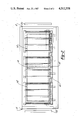
- FIG. 1 is an end view illustrating a preferred embodiment of the present invention and with parts removed for clarity;
- FIG. 2 is a view taken substantially line 2--2 in FIG. 1 and with parts removed for clarity;
- FIG. 3 is an exploded perspective view illustrating the preferred embodiment of the present invention and with parts removed for clarity;
- FIG. 4 is a cross-sectional view taken substantially along line 4--4 in FIG. 1 and enlarged for clarity.
- a portion of a metallurgical furnace is thereshown having an elongated furnace chamber 10 which is generally square in cross-sectional shape and open at each end 12 and 14.
- the furnace chamber 10 is surrounded by insulation panels 16 while one or more heating coils 18 are positioned within the furnace chamber 10 and closely adjacent the insulation panels 16.
- the heating coils 18 will be subsequently described in greater detail.
- a first door or hatch 20 provides access to one end 12 of the furnace chamber 10 while a second hatch 22 provides access to the other end 14 of the furnace chamber 10.
- a plurality of cylindrical rollers 30 are rotatably mounted to the bottom of the furnace chamber 10 by roller mounts 32.
- the rollers 30 are preferably arranged in two longitudinally extending rows 34 and 36 so that the rollers 30 in each row 34 and 36 are spaced apart and parallel with respect to each other.
- the rollers 30 in one row 34 are coaxial with the rollers 30 in the other row 36 so that the axis of each roller 30 is transverse with respect to the longitudinal axis of the furnace chamber 10.
- each roller 30 includes a cylindrical axle 38 which extends between and is secured to the roller mounts 32.
- a tubular and cylindrical tube 40 is positioned coaxially around and spaced radially outwardly from the shaft 38 while cylindrical roller bearings 42 are positioned in between the axle 38 and roller tube 40 so that the tube 40 freely rotates with respect to the axle 38.
- the axle 38, roller bearings 42 and roller tube 40 are all constructed of a high temperature deformation resistant material, such as graphite or consolidated carbon. Such a material is necessary since the rollers remain within the furnace chamber during the heat treating metallurgical process.
- the rollers 32 are adapted to frictionally engage the bottom 50 of a carrier or coffin 52 in which the parts to be heat treated are contained.
- the coffin 52 is generally conventional in construction except that it includes two upwardly extending longitudinal channels 54 formed in its bottom 50. Each channel 54 registers with one row 34 or 36 of the rollers 30 so that the portion of the rollers 30 are positioned within the channels 54.
- the rollers 30 rotatably support and guide the coffin 52 into the interior of the furnace chamber 10.
- stop 60 is secured to a midpoint of the furnace bottom so that the stop 60 extends transversely across the bottom.
- the stop 60 together with the dual access doors 20 and 22 enable one coffin 52 to be loaded into the furnace chamber 10 from each end.
- the stop 60 is dimensioned so that it abuts against the inner end of each coffin 52 thus limiting the extension of the coffins 52 into the furnace chamber 10.
- Each heating coil 18 is generally rectangular in shape and includes two sides 72 and 74, a top 76 and a bottom 78.
- a unitary bus bar 80 is positioned at the corner between the side 74 and top 76 while a bus bar containing two separated parts 82 and 84 is provided at each other corner of the heating coil 18.
- a pair of heating rods 86 extend between and are connected with each registering pair of bus bar parts 82 or 84 or with the unitary bus bar 80.
- a source of electrical power is interconnected between the bus bar parts 82 and 84 at the corner of the heating coil 18 which is diagonal from the unitary bus bar 80. Consequently, electrical power from the source 88 first flows through the heating rods 86 which interconnect the bus bar parts 82 to the bus bar 80. From the bus bar 80, the current flows through the heating rods 86 which interconnect the bus bar parts 84 and back to the power source 88.
- the construction of the heating coil 18 is advantageous in several different respects.
- the heating rods 86 extending along the sides 72 and 74, top 76 and bottom 78 of the heating coil are equal in length, the electrical current is equally distributed or balanced in each heating rod 86 thus providing a uniform temperature for each heating rod 86 and thus a uniform temperature for the furnace chamber 10.
- only two heating coils 86 extend in between the bus bar parts 82 or 84 and/or the unitary bus 80, any thermal distortion of the heating coil 18 caused by thermal expansion of the heating coils 86 will be compensated for automatically. This automatic compensation may result in slight twisting of the parallelogram formed by a pair of heating rods 86 and the bus bar parts 82 or 84 but otherwise will not damage the heating coil.
- the present invention provides a unique coffin delivery system for a metallurgical furnace. Since the rollers automatically guide the coffin into the interior of the furnace chamber, only a very small clearance between the coffin and the heating coils 18 is required.
- a still further advantage of the present invention is the provision of the heating coil 18 which allows the electrical power source to be connected between two adjacent bus bar parts 82 and 84 at the bottom of the furnace chamber and still obtain an automatic balance of the electical current through the heating rods 86.
- a still further advantage of the heating coil of the present invention is that slight thermal distortion of the heating coil does not damage the heating coil.
Landscapes
- Engineering & Computer Science (AREA)
- Chemical & Material Sciences (AREA)
- Mechanical Engineering (AREA)
- General Engineering & Computer Science (AREA)
- Metallurgy (AREA)
- Thermal Sciences (AREA)
- Crystallography & Structural Chemistry (AREA)
- Materials Engineering (AREA)
- Physics & Mathematics (AREA)
- Organic Chemistry (AREA)
- Tunnel Furnaces (AREA)
- Furnace Charging Or Discharging (AREA)
- Vertical, Hearth, Or Arc Furnaces (AREA)
- Furnace Details (AREA)
- Crucibles And Fluidized-Bed Furnaces (AREA)
- Paper (AREA)
Priority Applications (8)
| Application Number | Priority Date | Filing Date | Title |
|---|---|---|---|
| US06/567,769 US4512558A (en) | 1984-01-03 | 1984-01-03 | Coffin delivery system for metallurgical furnace |
| EP85900843A EP0167618B1 (de) | 1984-01-03 | 1985-01-02 | Transportplattenzuführungssystem für einen metallurgischen ofen |
| PCT/US1985/000015 WO1985003087A1 (en) | 1984-01-03 | 1985-01-02 | Coffin delivery system for metallurgical furnace |
| AT85900843T ATE78062T1 (de) | 1984-01-03 | 1985-01-02 | Transportplattenzufuehrungssystem fuer einen metallurgischen ofen. |
| DE8585900843T DE3586300D1 (de) | 1984-01-03 | 1985-01-02 | Transportplattenzufuehrungssystem fuer einen metallurgischen ofen. |
| JP60500314A JPS61500984A (ja) | 1984-01-03 | 1985-01-02 | 治金用炉のコフイン受渡し装置 |
| ZA8535A ZA8535B (en) | 1984-01-03 | 1985-01-03 | Coffin delivery system for matallurgical furnace |
| US06/703,182 US4554441A (en) | 1984-01-03 | 1985-02-19 | Electric heating coil |
Applications Claiming Priority (1)
| Application Number | Priority Date | Filing Date | Title |
|---|---|---|---|
| US06/567,769 US4512558A (en) | 1984-01-03 | 1984-01-03 | Coffin delivery system for metallurgical furnace |
Related Child Applications (1)
| Application Number | Title | Priority Date | Filing Date |
|---|---|---|---|
| US06/703,182 Division US4554441A (en) | 1984-01-03 | 1985-02-19 | Electric heating coil |
Publications (1)
| Publication Number | Publication Date |
|---|---|
| US4512558A true US4512558A (en) | 1985-04-23 |
Family
ID=24268566
Family Applications (2)
| Application Number | Title | Priority Date | Filing Date |
|---|---|---|---|
| US06/567,769 Expired - Lifetime US4512558A (en) | 1984-01-03 | 1984-01-03 | Coffin delivery system for metallurgical furnace |
| US06/703,182 Expired - Fee Related US4554441A (en) | 1984-01-03 | 1985-02-19 | Electric heating coil |
Family Applications After (1)
| Application Number | Title | Priority Date | Filing Date |
|---|---|---|---|
| US06/703,182 Expired - Fee Related US4554441A (en) | 1984-01-03 | 1985-02-19 | Electric heating coil |
Country Status (7)
| Country | Link |
|---|---|
| US (2) | US4512558A (de) |
| EP (1) | EP0167618B1 (de) |
| JP (1) | JPS61500984A (de) |
| AT (1) | ATE78062T1 (de) |
| DE (1) | DE3586300D1 (de) |
| WO (1) | WO1985003087A1 (de) |
| ZA (1) | ZA8535B (de) |
Cited By (2)
| Publication number | Priority date | Publication date | Assignee | Title |
|---|---|---|---|---|
| US4802844A (en) * | 1988-01-20 | 1989-02-07 | Gas Research Institute | High capacity, retractable furnace hearth |
| CN109420815A (zh) * | 2017-08-25 | 2019-03-05 | 张跃 | 一种炉体内部系统 |
Citations (5)
| Publication number | Priority date | Publication date | Assignee | Title |
|---|---|---|---|---|
| US2978237A (en) * | 1956-09-20 | 1961-04-04 | Basic Products Corp | Heat treating apparatus |
| US3171759A (en) * | 1962-09-21 | 1965-03-02 | Ipsen Ind Inc | Method of heat treating high speed steels |
| US3718324A (en) * | 1971-11-12 | 1973-02-27 | Hayes Inc C I | Vacuum furnace and work cart for use therein |
| US4049473A (en) * | 1976-03-11 | 1977-09-20 | Airco, Inc. | Methods for carburizing steel parts |
| US4441698A (en) * | 1981-03-21 | 1984-04-10 | Ferdinand Limque | Furnace for the heat treatment of drills |
Family Cites Families (18)
| Publication number | Priority date | Publication date | Assignee | Title |
|---|---|---|---|---|
| US1842981A (en) * | 1929-06-20 | 1932-01-26 | Michigan Steel Casting Company | Heat treating furnace and the like |
| US1788685A (en) * | 1930-03-11 | 1931-01-13 | Surface Comb Co Inc | Conveying apparatus |
| US2182202A (en) * | 1938-03-19 | 1939-12-05 | Henry H Harris | Roller rail for heat treating furnaces |
| US2167640A (en) * | 1938-05-31 | 1939-08-01 | Electric Furnace Co | Lubricating construction for roller rails for furnaces |
| US3004090A (en) * | 1958-04-01 | 1961-10-10 | Gen Electric Co Ltd | Heating element assemblies for electric furnaces |
| NL251128A (de) * | 1959-09-22 | |||
| DE1565398A1 (de) * | 1965-09-03 | 1970-04-16 | Atomic Energy Of Australia | Heizstab fuer elektrische Widerstandsoefen und unter Verwendung solcher Staebe gebildete Heizeinrichtung |
| US3782705A (en) * | 1971-12-14 | 1974-01-01 | Hayes Inc C I | Continuously operated vacuum furnace having work part transfer conveyor and load and unload mechanism |
| JPS5156631A (ja) * | 1974-11-13 | 1976-05-18 | Fuji Photo Film Co Ltd | Gazokeiseiho |
| US3984616A (en) * | 1975-10-14 | 1976-10-05 | Btu Engineering Corporation | High temperature furnace heater |
| US4124199A (en) * | 1977-07-11 | 1978-11-07 | Abar Corporation | Process and apparatus for case hardening of ferrous metal work pieces |
| US4132886A (en) * | 1977-10-14 | 1979-01-02 | Norton Company | Heating element |
| US4126757A (en) * | 1978-01-25 | 1978-11-21 | Autoclave Engineers, Inc. | Multizone graphite heating element furnace |
| JPS5618285A (en) * | 1979-07-23 | 1981-02-20 | Takasago Kogyo Kk | Roller type tunnel furnace and refractory disc for baking work therein |
| EP0042029A1 (de) * | 1980-06-18 | 1981-12-23 | Hoesch Aktiengesellschaft | Transportrolle für einen Glühofen |
| JPS5865795U (ja) * | 1981-10-28 | 1983-05-04 | 株式会社神戸製鋼所 | 熱間静水圧処理装置における加熱装置 |
| DE3242959C2 (de) * | 1981-11-20 | 1986-02-20 | Kabushiki Kaisha Kobe Seiko Sho, Kobe | Isostatische Heißpreßvorrichtung |
| JPH0243806B2 (ja) * | 1982-12-17 | 1990-10-01 | Daido Steel Co Ltd | Roorahaasushikikanetsuro |
-
1984
- 1984-01-03 US US06/567,769 patent/US4512558A/en not_active Expired - Lifetime
-
1985
- 1985-01-02 JP JP60500314A patent/JPS61500984A/ja active Pending
- 1985-01-02 DE DE8585900843T patent/DE3586300D1/de not_active Expired - Lifetime
- 1985-01-02 AT AT85900843T patent/ATE78062T1/de not_active IP Right Cessation
- 1985-01-02 EP EP85900843A patent/EP0167618B1/de not_active Expired - Lifetime
- 1985-01-02 WO PCT/US1985/000015 patent/WO1985003087A1/en not_active Ceased
- 1985-01-03 ZA ZA8535A patent/ZA8535B/xx unknown
- 1985-02-19 US US06/703,182 patent/US4554441A/en not_active Expired - Fee Related
Patent Citations (5)
| Publication number | Priority date | Publication date | Assignee | Title |
|---|---|---|---|---|
| US2978237A (en) * | 1956-09-20 | 1961-04-04 | Basic Products Corp | Heat treating apparatus |
| US3171759A (en) * | 1962-09-21 | 1965-03-02 | Ipsen Ind Inc | Method of heat treating high speed steels |
| US3718324A (en) * | 1971-11-12 | 1973-02-27 | Hayes Inc C I | Vacuum furnace and work cart for use therein |
| US4049473A (en) * | 1976-03-11 | 1977-09-20 | Airco, Inc. | Methods for carburizing steel parts |
| US4441698A (en) * | 1981-03-21 | 1984-04-10 | Ferdinand Limque | Furnace for the heat treatment of drills |
Cited By (2)
| Publication number | Priority date | Publication date | Assignee | Title |
|---|---|---|---|---|
| US4802844A (en) * | 1988-01-20 | 1989-02-07 | Gas Research Institute | High capacity, retractable furnace hearth |
| CN109420815A (zh) * | 2017-08-25 | 2019-03-05 | 张跃 | 一种炉体内部系统 |
Also Published As
| Publication number | Publication date |
|---|---|
| JPS61500984A (ja) | 1986-05-15 |
| ATE78062T1 (de) | 1992-07-15 |
| EP0167618B1 (de) | 1992-07-08 |
| WO1985003087A1 (en) | 1985-07-18 |
| EP0167618A1 (de) | 1986-01-15 |
| US4554441A (en) | 1985-11-19 |
| ZA8535B (en) | 1985-08-28 |
| EP0167618A4 (de) | 1986-12-16 |
| DE3586300D1 (de) | 1992-08-13 |
Similar Documents
| Publication | Publication Date | Title |
|---|---|---|
| DE69332639T2 (de) | Wagerechter diffusionsofen mit hoher leistung | |
| US4517448A (en) | Infrared furnace with atmosphere control capability | |
| US4245613A (en) | Tunnel oven | |
| WO2000024227A8 (en) | Temperature control system and method for heating and maintaining medical items at desired temperatures | |
| US4147888A (en) | Electric heating element for electric resistance furnaces | |
| JPS61246589A (ja) | グラフアイトの加熱要素を備えた電気熱処理炉 | |
| US4554441A (en) | Electric heating coil | |
| US4591337A (en) | Heat treatment furnace with crown-shaped transport path for the workpieces | |
| PL256320A1 (en) | Supporting structure for loading products in heat-treating furnace | |
| EP2313533B1 (de) | Retortenofen mit entkoppelter chargenaufnahme, zur wärmebehandlung von metallischen werkstücken | |
| EP0208249B1 (de) | Ofenwagen | |
| EP0173005B1 (de) | Backofen mit Heissluftumwälzheizung | |
| US4836777A (en) | Kiln cars | |
| US4664692A (en) | Heat treatment furnace for glass | |
| EP0061158B1 (de) | Verfahren zum Einbrennen von elektronischen Dickschichtschaltungen | |
| DE2810685A1 (de) | Vorrichtung zum aufbewahren von fertiggerichten | |
| EP0088995A1 (de) | Drehherdofen | |
| DE2126329B2 (de) | Brennstoffbeheizter haengebahnofen | |
| DE19648366C1 (de) | Anlage zur thermischen Behandlung von Produkten | |
| EP0175248B1 (de) | Backofen mit Heissluftumwälzheizung | |
| JPH05295424A (ja) | 被処理材の熱処理方法 | |
| US3887327A (en) | Tunnel kiln for the heat treatment of products having a circular cross-section | |
| JP2996710B2 (ja) | セラミック電子部品の焼成方法、焼成炉及び焼成装置 | |
| JPS6467888A (en) | Induction heater for slab material | |
| GR3020352T3 (en) | Kiln with displaceable frames for the firing of manufactured articles |
Legal Events
| Date | Code | Title | Description |
|---|---|---|---|
| AS | Assignment |
Owner name: ULTRA-TEMP CORPORATION 42219 IRWIN, MT. CLEMENS, M Free format text: ASSIGNMENT OF ASSIGNORS INTEREST.;ASSIGNOR:LUETH, ROY C.;REEL/FRAME:004350/0810 Effective date: 19850110 |
|
| STCF | Information on status: patent grant |
Free format text: PATENTED CASE |
|
| CC | Certificate of correction | ||
| FEPP | Fee payment procedure |
Free format text: PAYOR NUMBER ASSIGNED (ORIGINAL EVENT CODE: ASPN); ENTITY STATUS OF PATENT OWNER: SMALL ENTITY |
|
| FPAY | Fee payment |
Year of fee payment: 4 |
|
| FPAY | Fee payment |
Year of fee payment: 8 |
|
| REMI | Maintenance fee reminder mailed | ||
| REFU | Refund |
Free format text: REFUND OF EXCESS PAYMENTS PROCESSED (ORIGINAL EVENT CODE: R169); ENTITY STATUS OF PATENT OWNER: SMALL ENTITY |
|
| FPAY | Fee payment |
Year of fee payment: 12 |
|
| SULP | Surcharge for late payment |