US4537504A - Security blank with enhanced authenticating features, and a method and an apparatus for determining the genuineness of the security blank - Google Patents
Security blank with enhanced authenticating features, and a method and an apparatus for determining the genuineness of the security blank Download PDFInfo
- Publication number
- US4537504A US4537504A US06/342,065 US34206582A US4537504A US 4537504 A US4537504 A US 4537504A US 34206582 A US34206582 A US 34206582A US 4537504 A US4537504 A US 4537504A
- Authority
- US
- United States
- Prior art keywords
- light
- bundles
- light rays
- security
- blank
- Prior art date
- Legal status (The legal status is an assumption and is not a legal conclusion. Google has not performed a legal analysis and makes no representation as to the accuracy of the status listed.)
- Expired - Fee Related
Links
Images


Classifications
-
- G—PHYSICS
- G07—CHECKING-DEVICES
- G07F—COIN-FREED OR LIKE APPARATUS
- G07F7/00—Mechanisms actuated by objects other than coins to free or to actuate vending, hiring, coin or paper currency dispensing or refunding apparatus
- G07F7/08—Mechanisms actuated by objects other than coins to free or to actuate vending, hiring, coin or paper currency dispensing or refunding apparatus by coded identity card or credit card or other personal identification means
- G07F7/086—Mechanisms actuated by objects other than coins to free or to actuate vending, hiring, coin or paper currency dispensing or refunding apparatus by coded identity card or credit card or other personal identification means by passive credit-cards adapted therefor, e.g. constructive particularities to avoid counterfeiting, e.g. by inclusion of a physical or chemical security-layer
-
- G—PHYSICS
- G06—COMPUTING OR CALCULATING; COUNTING
- G06K—GRAPHICAL DATA READING; PRESENTATION OF DATA; RECORD CARRIERS; HANDLING RECORD CARRIERS
- G06K19/00—Record carriers for use with machines and with at least a part designed to carry digital markings
- G06K19/06—Record carriers for use with machines and with at least a part designed to carry digital markings characterised by the kind of the digital marking, e.g. shape, nature, code
- G06K19/08—Record carriers for use with machines and with at least a part designed to carry digital markings characterised by the kind of the digital marking, e.g. shape, nature, code using markings of different kinds or more than one marking of the same kind in the same record carrier, e.g. one marking being sensed by optical and the other by magnetic means
- G06K19/10—Record carriers for use with machines and with at least a part designed to carry digital markings characterised by the kind of the digital marking, e.g. shape, nature, code using markings of different kinds or more than one marking of the same kind in the same record carrier, e.g. one marking being sensed by optical and the other by magnetic means at least one kind of marking being used for authentication, e.g. of credit or identity cards
- G06K19/16—Record carriers for use with machines and with at least a part designed to carry digital markings characterised by the kind of the digital marking, e.g. shape, nature, code using markings of different kinds or more than one marking of the same kind in the same record carrier, e.g. one marking being sensed by optical and the other by magnetic means at least one kind of marking being used for authentication, e.g. of credit or identity cards the marking being a hologram or diffraction grating
-
- G—PHYSICS
- G06—COMPUTING OR CALCULATING; COUNTING
- G06K—GRAPHICAL DATA READING; PRESENTATION OF DATA; RECORD CARRIERS; HANDLING RECORD CARRIERS
- G06K7/00—Methods or arrangements for sensing record carriers, e.g. for reading patterns
- G06K7/10—Methods or arrangements for sensing record carriers, e.g. for reading patterns by electromagnetic radiation, e.g. optical sensing; by corpuscular radiation
- G06K7/14—Methods or arrangements for sensing record carriers, e.g. for reading patterns by electromagnetic radiation, e.g. optical sensing; by corpuscular radiation using light without selection of wavelength, e.g. sensing reflected white light
Definitions
- German Patent DE2538875 which includes a light-redirecting spatial structure establishing at least one authenticating feature.
- the method includes the steps of illuminating the spatial structure, forming from light scattered from the spatial structure two narrow bundles of light rays, converting the two bundles of light rays into electric signals, determining a characteristic measurement value for the spatial structure, and forming "yes" or "no" outputs in dependence of the characteristic measurement value.
- the document includes a phase diffraction grating, which diffracts or bends the energy obtained from a light source in a predetermined ratio along individual specified directions. When examining the document and determining whether or not it is genuine, it is considered genuine when the diffractions of light energy distributed along certain directions have a predetermined ratio to one another.
- German Patent DE2814890 it is also known to determine the genuineness of a document which has a phase diffraction grating embedded therein, by comparing the intensity of light diffracted along a certain direction with the intensity of diffusely scattered light.
- the present invention is based on the recognition that the object of the invention can be attained by the further development and practical application of scientific theoretical investigations dealing with the subject of inverse optical problems remote from the field of the present invention. From the International U.R.S.I. Symposium on electromagnetic waves held in Kunststoff, Federal Republic of Germany from Aug. 26 to Aug. 29, 1980, and as stated on pages 315C/1 to 315C/2, that in a partially coherent source having a periodic phase profile obtained by the superposition of a phase diffraction grating and a randomly diffusing element, the presence of the periodic phase profile can be established more easily by measuring the degree of coherence of scattered light rays than the intensity thereof.
- This object is attained in a method of determining the genuineness of a security blank having a light-redirecting spatial structure establishing at least one authenticating feature, which includes illuminating the spatial structure, forming from light scattered from the spatial structure two narrow bundles of light rays, and converting the two bundles of light rays into electrical signals, by the improvement which comprises the steps of determining the degree of coherence between the two bundles of light rays, forming "yes” or “no" outputs in dependence of the degree of coherence determined, and ascertaining from the outputs information pertaining to the genuineness of the security blank.
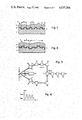
- FIG. 1 is a cross-section of a security blank including an authenticating feature
- FIG. 2 is another cross-section of the security blank including another version of an authenticating feature
- FIG. 3 is a block diagram of a first apparatus for determining the genuineness of a security blank
- FIG. 4 is a diagram of the intensity of interference fringes as a function of the path- or phase-difference of two coherent light rays
- FIG. 5a is a diagram of the intensity versus the deflection of a phase diffraction grating having a grating constant g, where the intensity is determined by conventional methods;
- FIG. 5b is a diagram of the intensity versus the deflection angle of a diffuse scatterer having a correlation length l, where the intensity is measured by conventional methods;
- FIG. 5c is a superposition of a diffraction grating and a diffuse scatterer, where l is approximately equal to g, showing light intensity versus the deflection angle;
- FIG. 5d is a superposition of a diffraction grating and a diffuse scatterer, where l is approximately g/10, showing light intensity versus the deflection angle;
- FIG. 5e is a superposition of a diffraction grating and a diffuse scatterer, where l is approximately g/20, showing light intensity versus the deflection angle;
- FIG. 6a is a plot of intensity versus the deflection angle of a phase diffraction grating having a diffraction constant g, according to the method of the present invention
- FIG. 6b is a plot of intensity versus the deflection angle of a purely diffuse scatterer having a correlation length l, according to the method of the present invention.
- 6c is a plot of intensity versus the deflection angle of phase diffraction grating and a diffuse scatterer where l is approximately equal to g;
- FIG. 6c is a plot of intensity versus the deflection angle of phase diffraction grating and a diffuse scatterer where l is approximately equal to g/10, according to the method of the present invention
- FIG. 6e is a plot of intensity versus the deflection angle when a diffuse scatterer is superimposed on a phase diffraction grating, where l is approximately equal to g/20;
- FIG. 7 is a second version of an apparatus for determining the genuineness of a security document
- FIG. 8 is a diagram of the intensity of the interference fringes of two coherent light waves as the function of the phase difference or path length between two light beams;
- FIG. 9 is a diagram of the intensity versus phase difference similar to FIG. 8, but at an angular position of the security document having light incident thereon at an angle other than 90°;
- FIG. 10 is a diagram of the contrast, which is a relation of the maxima and minima of the intensities shown in FIG. 8, versus the phase difference or path length of two coherent light sources when the security document has light incident thereon at an angle of 90°;
- FIG. 11 is a third version of an apparatus for determining the genuineness of a security blank
- FIG. 12 is a fourth version of an apparatus for determining the genuineness of a security blank
- FIG. 13 is a schematic diagram illustrating a method of illuminating a document or security blank which includes a deterministic component and a stochastic component, so that its genuineness cannot easily be determined by intensity measurement, but can be determined by measurement of coherence of light rays passing through the authenticating features;
- FIG. 14 is a diagram of the absolute value of the contrast as a function of deflection angle
- FIG. 15 is a cross-section of a security blank including a carrier and an authenticating feature in the form of a strip embedded therein;
- FIG. 16 is a cross-section of the security blank similar to FIG. 15, but showing another cross-sectional shape of the authenticating feature
- FIG. 17 is a cross-section of a security blank illustrating a ray dividing device
- FIG. 18 is a cross-section of a security blank similar to FIG. 15, but showing an authenticating feature including a reflection layer;
- FIG. 19 is a cross-section of a security blank similar to FIG. 15, but where the authenticating feature has an irregular cross-section;
- FIG. 20 is a fifth version of an apparatus for determining the genuineness of a security blank
- FIG. 21 is a sixth version of an apparatus for determining the genuineness of a security blank
- FIG. 22 is an image of contrast obtained from the apparatus shown in FIG. 20 with an odd number of image reversals;
- FIG. 23 corresponds to FIG. 22 but with an even number of image reversals
- FIG. 24 is a diagram of contrast versus deflection angle according to the apparatus of FIG. 20;
- FIG. 25 is a diagram of contrast versus deflection angle according to the apparatus of FIG. 21;
- FIG. 26 is a diagram of intensity versus deflection angle of interference fringes according to the apparatus of FIG. 20;
- FIG. 27 is a diagram of intensity versus deflection angle of interference fringes according to the apparatus of FIG. 21;
- FIG. 28 is a seventh version of an apparatus for determining the genuineness of security documents
- FIG. 29 is an eighth version of an apparatus for determining the genuineness of a security blank
- FIG. 30 is a cross-section of a security blank in which an authenticating feature is embedded at an angle to the main surface of the security blank;
- FIG. 31 is a perspective view of the authenticating feature of FIG. 30;
- FIG. 32 is a cross-section of a security blank containing an authenticating feature with a microscopically superimposed diffusing feature
- FIG. 33 is a cross-section of a security blank including an authenticating feature embedded therein, and a partially light-transparent reflective layer superimposed thereon;
- FIG. 34 is a perspective view of a security thread used for embedding in a security blank, which has a cross-section other than circular or rectangular, and a microscopic embossment structure on its surface.
- the document or security blank illustrated in FIG. 1 may be a credit card, an identity card, a railroad ticket, bank note, airline ticket, check or the like. It includes one of several authenticating features in the form of a spatial structure 2 including a deterministic component 2', which deflects light incident thereto by diffraction or bending of the transmitted or reflected light in at least one predetermined direction, and may be implemented by a phase hologram, a phase diffraction grating, kinoform, or the like, and the genuineness of which may be examined in an automated test apparatus based on light scattered from the structure 2.
- a deterministic component 2' which deflects light incident thereto by diffraction or bending of the transmitted or reflected light in at least one predetermined direction
- a phase hologram a phase diffraction grating, kinoform, or the like
- the deterministic component 2' consists of a phase diffraction grating, which has been embedded in a substantially flat thermoplastic substrate 3, and is covered with a thin reflection layer 4.
- the coarse surface of the protecting layer 5 forms a stochastic and diffusely scattering component 2", of the structure 2 which is superimposed on the deterministic component 2'. It is advantageous if the substrate 3 is non-transparent to light, and if the protecting layer 5 is transparent only for infrared light, so that at least the deterministic component 2' of the structure 2 is hidden from the human eye.
- Typical measurement distances of the deterministic component 2' in the case of a diffraction grating the grating constant, have been denoted in FIG. 1 with g, and the correlation length of the stochasting component 2" has been denoted as l.
- the correlation length l is, simply expressed, the average particle size of the surface roughness of the stochastic component 2".
- l represents the length, which taken along a stochastic height dimension h(s) is a function of the length dimension s, and still shows a certain correlation, namely h(s) can still be statistically correlated with h(s ⁇ l).
- h is the height dimension and s the longitudinal dimension of the stochastic component 2".
- the protective layer 5 may, for example, also consist of a material having a spatially fluctuating index of refraction and have a smooth surface.
- the correlation l of the stochastic component roughly speaking, will be understood as the average "particle size" of the fluctuation of the refractive index.
- the document 1' of FIG. 2 differs from the document 1, in that the phase diffraction grating is disposed on an undulatory surface, namely a surface other than the flat surface of the substrate 3, forming the stochastic component of the structure 2.
- a light source 6 irradiates a document 1 or 1' by means of a light ray 7.
- the light ray 7 should at least be quasi-monochromatic, namely emit light at a selected wavelength, and have a certain spatial coherence, namely the correlation length immediately ahead of structure 2 should be at least equal to typical measurement distances g of the deterministic component 2'.
- the cross-section of the ray should, however, be large in comparison to the typical measurement distances g.
- light will be used, even though it will be understood to include also invisible light, such as light in the ultraviolet and infrared spectrum.
- the light reflected from the structure 2 is made to impinge on two light-sorting members 8 and 9, each passing a narrow light bundle 10 or 11 at a preferably adjustable average scattering angle ⁇ or ⁇ '.
- the bundle of rays 10 passes through a deflecting member 12, a path difference member 13, as well as another deflecting member 14 to a superimposing or superposition member 17, and correspondingly the bundle of rays 11 passes through deflection members 15 and 16 to the same superimposing or superposition member 17, which reunites the bundles of light rays 10 and 11.
- the path difference member 13 generates a variable optical path difference between the bundle of light rays 10 and 11.
- Mirrors, prisms, optical fibers, electro-optical deflectors and the like may serve as deflecting members 12, 14, 15 and 16; a prism, movable mirror, a medium with a variable index of refraction and the like may serve as a path difference member 13, for example, and a semi-transparent mirror, a fiber-optical link and the like may serve as a superimposing or superposition member 17.
- the reunited bundle of rays 10 and 11 impinge on photoelectric means 18, which may be implemented, for example, by a silicon diode, a photomultiplier, or the like.
- the photoelectric means 18 is connected to an electronic signal processor 19, to which there is postcoupled an electronic decision circuit 20.
- a (non-illustrated) control apparatus controls the sequence of examining the document or security blank for genuineness, by providing the required mechanical or electronic adjustment signals, enabling signals or stop signals, and passing them to the members 6, 8, 9, 13, 18, 19 and 20. But it may also operate a (non illustrated) drive, which, as a result of parallel displacement of the document 1, permits the establishment of an average value of the measurement, which will be described in what follows.
- the control drive switches the light source 6 on, and on the light-sensitive surface of the photoelectric means 18 there appear interference fringes, in view of the interference between the bundle of rays 10 and 11.
- the control drive controls the path difference member 13 so that the path difference ⁇ is continuously changed. As can be seen from FIG.
- is a value depending on the degree of coherence of the bundles of light rays 10 and 11, and is passed to the decision means 20 as a measurement value to form a "yes" signal, or a "no" signal.
- the decision means 20 determines that the document or security blank 1 is genuine and therefore generates a "yes” signal, if the measurement value of the contrast
- the contrast is in general a function of the scattering angle ⁇ , ⁇ ' namely
- FIGS. 5a through 5e show intensity measurements made on various spatial structures according to the known intensity measurement methods obtaining angular intensities ⁇ I( ⁇ )> of the scattered radiation, wherein the brackets ⁇ . . . . > denote the average value.
- the various figures apply for the following structures:
- FIGS. 5a and 6a apply to a pure phase diffraction grating having a grating constant g;
- FIGS. 5b and 6b only apply to a purely diffuse scatterer having a correlation length l;
- FIGS. 5c and 6c apply to the superposition of a phase diffraction grating and of a diffuse scatterer having a correlation length l ⁇ g;
- FIGS. 5d and 6d apply to the superposition of a phase diffraction grating with a diffuse scatterer having a correlation length l ⁇ g/10;
- FIGS. 5e and 6e apply to the superposition of a phase diffraction grating with a diffuse scatterer having a correlation length l ⁇ g/20.
- the degree of coherence measurement described permits a reliable determination pertaining to the genuineness of the document, even when the authenticating feature is strongly perturbed by a stochasting component, and even if the examination pertaining to the genuineness of the document is rendered more difficult by intensity distribution, or even made impossible thereby.
- the measurement of the degree of coherence therefore permits recognition of the authenticating features in the form of phase diffraction gratings, holograms and the like which, for example are disposed on a coarse surface, or whose pattern is worn and therefore rendered more diffuse.
- the probability against successful forging can be further increased if, for example according to FIGS. 1 and 2, a stochastic and diffusely scattering component 2" is superimposed on the deterministic component 2' of the structure 2, which renders recognition of the function of an authenticating feature by intensity measurement more difficult, or makes it impossible, but which still permits recognition thereof by measurement of the degree of coherence.
- a stochastic and diffusely scattering component 2" is superimposed on the deterministic component 2' of the structure 2, which renders recognition of the function of an authenticating feature by intensity measurement more difficult, or makes it impossible, but which still permits recognition thereof by measurement of the degree of coherence.
- the correlation length l of the stochastic component 2" is at most one-fifth of the typical measurement g of the deterministic component 2'.
- FIG. 7 is a special and particularly simple apparatus for an interferometric measurement of the degree of coherence; parts identical to those shown in FIG. 3 have been given the same reference numerals.
- the bundle of light rays 10 and 11 are sorted out by means of mirrors 21 and 22, and deflected to a common detector plane 25 by means of two further mirrors 23 and 24.
- the document or security blank 1 is disposed on a (non-illustrated) and pivotable holder, which permits varying of the angle ⁇ between the surface of the document 1 and a plane at right angles to the axis of the ray of light.
- the detector plane 25 there are disposed two photoelectric detectors 26 and 27 in such a manner that one photoelectric detectors senses a light zone, and the other photoelectric detector a dark zone of the interference fringes appearing on the detector plane 25; a signal processing element 29 is postcoupled to the photoelectric detectors 26 and 27.
- the angle ⁇ is varied.
- the decision means 20 postcoupled to the signal processor 19 provides a "yes" signal, if the contrast
- the reliability of determining the genuineness of the document can be further increased if the "yes" signal is only generated when, upon pivoting the document 1, the change of contrast exceeds a predetermined value.
- FIG. 12 corresponds to the apparatus according to FIG. 3 as far as elements 6, 8, 9, 12 and 15 are concerned.
- the light bundles 10 or 11 re-routed by the deflection members 12 or 15, respectively, impinge on photoelectric detection means 28 and 29, respectively.
- the photoelectric detection means 28 and 29 are connected to the signal processing means 30, a decision means 31 being postcoupled to the signal processing means 30.
- the signal processing means 30 operates as an electronic correlator and obtains the intensity correlation g.sup.(2) ( ⁇ , ⁇ ') according to the equation ##EQU1##
- the decision means 31 At the output of the decision means 31 there appears a "yes" signal, if the intensity correlation g.sup.(2) exceeds a predetermined threshold.
- FIG. 12 there is shown a special and particularly simple apparatus for measuring the intensity correlation.
- the photoelectric detectors 28 and 29 serve both as sorting means for the bundle of light rays 10 and 11, and as detection means.
- a single photodetector can be used.
- the function I( ⁇ ) and the measurement values are stored digitally or in an analog manner; then the function I( ⁇ ') is determined therefrom and g.sup.(2) is calculated.
- a photodetector acting as a photomultiplier and of an electronic counter used as a memory, it is possible to implement this version at a low technical cost.
- Such correlation measurement methods are known, for example from the book "Photocorrelation and Light Beating Spectoscopy" 1974 Plenum Press, New York, and will therefore not be discussed here in further detail.
- FIGS. 13 to 19 there will be illustrated a method which is more compatible with conventional methods of manufacturing a document than the embedding of macroscopically fine light-bending structures, but which still provides a low probability of successful forgery, and where the authenticating feature is hidden from the human eye.
- the security blank 41 in FIG. 13 may be a document, a bank note, a credit card, an identity card, a railroad ticket, an airline ticket, a check or the like.
- a carrier 42 of the security blank 41 consists, for example of synthetic material, paper or cardboard.
- An authenticating feature in the form of a spatial structure 43 is embedded in the carrier 42, which is formed of a macroscopic (deterministic) optical element 43', and of a scattering element 43".
- the macroscopic optical element 43' is formed so that it deflects a light beam 44 incident on the document 41 according to the laws of geometrical optics to at least two predetermined directions 45 and 46, by bending or reflection, (in the illustrated example by bending), and wherein the light beam 44 has a certain spatial coherence.
- the scattering element namely the stochastic element 43" is in effect superimposed onto the macroscopic optical element 43', and causes a diffuse scattering of the light beam 44 in such a manner, that recognition of the function of the macroscopic optical element 43' by means of the intensity pattern 47 of the scattered light is at least rendered much more difficult, if not impossible, while the scattered light is still mutually coherent along the predetermined directions 45 and 46.
- the scattering element 43" may be formed by the material and/or the surface structure of the carrier 42, or of the optical element 43'.
- the scattering angle of an arbitrary ray 48 of the total light scattered from the structure 43 is designated in FIG. 13 as ⁇ ; the angle between the ray 48 and a ray 49 symmetrical thereto about an axis perpendicular to the surface of the carrier 1, when a ray of light 44 is incident at right angles to the surface of the document 41 is denoted as ⁇ , and the scattering angle of the rays 45 and 46 scattered in respective predetermined directions is denoted as ⁇ s or - ⁇ s .
- the light ray 44 is generated by means of an automatically operating test apparatus from a light source, and the structure 43 is illuminated thereby. From the light scattered from the structure 43 two narrow light beams 45 and 46 are extracted along the predetermined directions 45 and 46. By means of a photodetector and an electronic signal processor there is obtained a measurement value from the two light beams 45 and 46 in dependence of their mutual degree of coherence. From this measurement value there is obtained a "yes" signal or a "no" signal.
- the document 41 is regarded as genuine when the degree of coherence, namely the contrast
- the devices shown in FIGS. 3,7,11 and 12 may be used for determining the degree of coherence.
- FIG. 14 there is shown the degree of dependence of the contrast
- reaches at ⁇ 2 ⁇ s a definite maximum. Based on this maximum it can therefore be shown by measuring the degree of coherence with great confidence that a macroscopic optical element 43' is present in the security blank 41.
- the authenticating features of the structure 43 remain hidden from the human eye, in view of the scattering element 43" scattering incident light thereon diffusely.
- the pattern of the light scattered from the structure 43 is as a rule a speckled pattern, which renders mrasurement of the degree of coherence more difficult, if the speckled pattern is static.
- This difficulty can, however, become circumvented by moving the document or security blank 41 during measurement of the degree of coherence, for example, continuously, and thus forming an average value of the resulting light pattern.
- the document 41 is advantageously moved in a direction parallel to the longitudinal axis of the optical element 43'.
- Ray dividers such as biprisms, partially light transmitting mirrors, reflecting elements having surfaces inclined to one another, and the like, may serve as the macroscopic optical element 43', which are then embedded in a material scattering the light diffusely, or have a surface which scatters the light diffusely. This will be explained in more detail by means of FIGS. 15 through 19.
- FIG. 15 there is shown a document 50, in whose carrier 42 there is embedded a strip 51.
- Each upper and lower surface of the strip 51 is formed with surfaces 52 and 53 inclined with respect to one another, in the example shown in FIG. 15, at an obtuse angle.
- the typical width of the strip 51 is of the order of 1 mm, while the length of the strip 51 may correspond to the length or width of the document 50.
- the strip 51 advantageously is made of metal, or a material covered with a metal layer, or of a transparent material.
- the carrier 42 may, for example, consist of a diffusely scattering paper, or of thermoplastic material having a diffusely scattering surface.
- FIG. 16 there is shown a document 54, including a carrier 42, in which there is embedded a strip 55 having a reflective surface.
- the strip 55 which in its unbent state has a rectangular cross section, but is here shown slightly bent about a center axis, so that two surfaces 52 and 53 are formed which are inclined at an obtuse angle to one another.
- the carrier of the document 56 according to FIG. 17 consists of two layers 57 and 58 of transparent synthetic plastic connected to one another.
- the outer surfaces of the layers 57 and 58 are smooth.
- the common separation surface 59 of the layers 57 and 58 is formed, however, so as to scatter light diffusely. It therefore forms, on one hand, a ray divider, or ray splitter, which splits a ray 60 incident at an angle to the document 56 into a ray 61 reflected from the common separating surface 59, and into a ray 62 transmitted through the document 56.
- the course separating surface 59 forms a scattering element, which scatters the light ray 60 diffusely.
- a narrow light bundle is sorted out from light scattered from the document 6 as shown by the rays 61, and another narrow light bundle in the form of a bundle of rays 62 is transmitted through the document 56, so as to measure the degree of coherence.
- FIG. 18 there is shown a document 63, having a carrier 42, in which there is embedded a transparent strip 64 having a rectangular cross section, and whose surface is coated with a thin and partially light-transmitting reflective layer 65.
- This reflective layer 65 acts as a ray divider, and forms a macroscopic optical element.
- the material for the surface structure of the carrier 42 may again serve as the diffuse scattering element.
- the examination for genuiness of the document is performed in a manner identical to that of the document 56.
- FIG. 19 a document 66, having an element 67 embedded in a carrier 42, which element 67 has an irregular cross-section bounded by a plurality of surfaces 68, which are inclined to one another. These surfaces 68 split any light incident thereon by reflection or refraction into a plurality of light rays, or light bundles, while the carrier 42 scatters light incident thereon diffusely. The scattered light is therefore mutually coherent in several predetermined directions. These predetermined directions are preferably arranged in a code pattern. When examining the document for genuiness, a plurality of narrow light bundles are sorted out or extracted, and the code is read out by measuring the degree of coherence.
- a light source 73 serves to illuminate the structure 72, which is at least quasi-monochromatic, and has a certain spatial coherence.
- Two narrow bundles of light rays formed from light scattered from the structure 72 are made to impinge on light-sorting members 74 and 75, or 74' and 75', respectively, which are formed to receive light only along respective predetermined directions, and which may contain one or more light deflecting elements, and means for generating a variable optical path difference between the bundle of light rays incident on element 74 and 75, or 74' and 75'.
- the average scattering angle of the two sorted out bundles of light rays is denoted as ⁇ 1 or ⁇ 2 .
- Detector means 77 including, for example, a photoelectric detector, receive the reunited bundle of light rays, and convert them into electrical signals; the detector means 77 include signal processing means and decision means which form a "yes" or "no" output.
- the various elements 73 through 77 may be mounted securely or movably on a (non-illustrated) base plate.
- the devices of FIGS. 20 and 21 differ from one another by the number of image reversals (for example mirror reversals) to which the bundle of light rays are subjected in the light sorting members 74 and 75, or 74' and 75', as well as in the superposition member 76, as they pass from the structure 72 up to the point when they are reunited.
- image reversals for example mirror reversals
- the number of image reversals is odd
- the number of image reversals is even.
- the type of superposition of the light rays obtained from the scattered light of the structure 72 is determined by the number of image reversals. If this number is odd, then the superposition results in an inverse image. If the number is even, then the superposition is normal.
- the inverse superposition corresponds to symmetrical scanning to test for coherence, and the normal superposition corresponds to asymmetrical scanning.
- an angular deviation ⁇ at the detector system 77 corresponds to an angular deviation ⁇ 1 or ⁇ 2 of the sorted-out bundle of rays.
- the inverse superposition is characterized by the fact that the angular deviations ⁇ 1 and ⁇ 2 each have a different sense, namely + or - (FIG. 20). During normal superposition the sense of the angular deviations ⁇ 1 and ⁇ 2 remain equal (FIG. 21).
- the number of image reversals is odd, and corresponds to symmetrical scanning; the sense of ⁇ 1 and ⁇ 2 differs.
- of the interference fringes appearing on the detector plane of the detector system 77 depends from the average scattering angles ⁇ 1 and ⁇ 2 , as well as from the angular deviation ⁇ .
- FIGS. 22 and 23 show the computer-determined function
- f( ⁇ 1 , ⁇ 2 ). in perspective for the case where the spatial structure 72 is a macroscopic ray divider, or ray splitter following the law of geometrical optics.
- FIGS. 24 and 25 show the dependence of the contrast
- the curves 79 and 80 result, as can be seen from FIGS. 23 and 25, which are relatively constant over a wide angular range.
- the maximal height of the curves 79 and 80 is, however, critically dependent from the selected principal directions, namely dependent from the scattering angles ⁇ 1 and ⁇ 2 . If sin ⁇ 1 -sin ⁇ 2 assumes a "suitable " value, then according to the curve 79 a considerable contrast
- Suitable values of sin ⁇ 1 -sin ⁇ 2 are determined by the diffraction or scattering properties of the structure 72 of the authenticating feature without being corrupted by any noise. Each pair of scattering directions, in which the structure 72 determines an intensity concentration of the scattered light, determines such a value.
- such suitable values are integral multiples of ⁇ /b, where ⁇ is a wavelength of the light source 73, and b the period of the diffraction.
- the following measurement method is preferred.
- the principal directions are set for suitable values of ⁇ 1 and ⁇ 2 . In general these directions are not limited to a certain plane, but for simplicity's sake they are described by the angles ⁇ 1 and ⁇ 2 . If the principal directions are so chosen that the difference sin ⁇ 1 -sin ⁇ 2 is matched to the properties of the authenticating feature, then there is shown in the detector plane a long series of distinct interference fringes, the intensities of which are shown in FIG.
- the aforedescribed apparatus is particularly suitable for measurements of intensity during normal superposition, that is during the presence of interfering fringes on the detector plane the intensity variation is advantageously used to obtain a measurement value to form the "yes" and "no" signals.
- This change of intensity is also a measure for the degree of coherence of the bundles of light rays, but can be measured more simply than the actual degree of coherence.
- FIG. 28 in which the same reference numeral have been used as those in FIG. 21, the change of intensity of the interference fringes in the detector plane can be obtained with the aid of a single photodetector 83, the position of which can be varied, corresponding to the angular deviation ⁇ (FIG.
- any change in intensity of the interference fringes can be used in conjunction with stored threshhold values or threshhold functions to form a "yes" or "no" decision pertaining to the genuineness of the document examined.
- a group of stationary photoelectric diodes can be used in lieu of a movable photoelectric diode.
- FIG. 29 A particularly simple apparatus for symmetrical scanning is shown in FIG. 29.
- the document 71 to be examined is disposed on a first leg of a V-shaped holder 84, the second leg of which has mounted a mirror 85 thereon.
- the light source 73 and the holder 84 with the document 71 and the mirror 85 are mounted on a (non-illustrated) frame, which is pivotable about an axis 86.
- a second group of elements which are stationary includes two light-sorting members 87 and 88 extracting light scattered from the document 71 only within a narrow angular range, and a detecting system 89.
- the detecting system 89 may contain a correlation measurement device, for example according to FIG. 11, or an interferometric device, for example, according to FIG. 3.
- the pivoting angle of the frame is denoted in FIG. 29 as ⁇ 1
- the external angle between the plane of the document 71 and the plane of the mirror 85 is denoted as ⁇
- the angle between the plane of the document 71 and the direction of incidence of the light is denoted as ⁇ .
- ⁇ denotes the angle between the first bundle of light rays incident on the light-sorting member 87, and the second bundle of rays scattered from the document 71, reflected from the mirror 85, and impinging on the light-sorting member 88,
- the average scattering angles of the two light bundles formed from the light scattered from the document 71 are again denoted as ⁇ 1 and ⁇ 2 , respectively.
- ⁇ 1 and ⁇ 2 may be varied in opposite respective directions.
- the sum of the angles ⁇ 1 and ⁇ 2 is defined by the equation
- a symmetrical scanning can also be achieved by varying the wavelength or frequency of the light source 73.
- FIG. 30 there is shown a document 90, in which a spatial structure 91 is disposed at an angle to the substantially parallel surfaces of the carrier 92.
- a spatial structure 91 is disposed at an angle to the substantially parallel surfaces of the carrier 92.
- the structure 91 can be still better hidden, if the document 90 consists of a diffusely scattering material, thus forming a stochastic scattering component.
- the structure 91 is preferably disposed on the carrier 92 at an angle as shown in FIG. 31. If a plurality of such carriers 92 with different respective orientations are embedded in the document 90, a structure is obtained having characteristic directions of diffraction or deflection, which are not all disposed in one plane.
- the 32 contains an embedded carrier 94 having a macroscopic sawtooth structure 95, and a microscopic structure 96 superimposed thereto.
- the macroscopic structure 95 causes a refraction or reflection, according to the laws of geometrical optics, and the microscopic structure 96 causes a characteristic deflection, again resulting in the fact that the characteristic directions of refraction or deflection are not all disposed in the same plane.
- FIG. 33 there is shown a document 97 with a carrier 98 embedded therein, which has a macroscopic diffraction structure 99 and a reflective layer 100 coated thereon, which is partially transparent to light.
- the reflective layer 100 forms a ray divider or a ray splitter, which splits a ray incident at an angle to the document 97 into two separate rays along a direction of reflection, and along a direction of transmission, respectively.
- the deflection structure 99 causes the rays to be divided or split even further in another plane.
- a stochastic scattering component is to be superimposed on the deterministic scattering component formed by the diffraction structure 99, and the reflective layer 100, then this can be accomplished in a simple manner by a purposely caused geometric roughness of the diffraction structure 99.
- FIG. 34 there is illustrated a security thread 101, which is embedded as an authenticating feature into the document.
- the macroscopic cross-section of the security thread 101 has a constant cross-section over a portion of its length differing from a rectangular cross section, or from a circular cross section, while its surface is formed as a microscopically embossed structure 102.
- the combination of the macroscopic cross-section with a microscopic embossed structure 102 results in an authenticating feature which is particularly difficult to forge, and which is distinguished by a plurality of characteristic directions of diffraction.
Landscapes
- Engineering & Computer Science (AREA)
- Physics & Mathematics (AREA)
- General Physics & Mathematics (AREA)
- Theoretical Computer Science (AREA)
- General Health & Medical Sciences (AREA)
- Toxicology (AREA)
- Artificial Intelligence (AREA)
- Computer Vision & Pattern Recognition (AREA)
- Electromagnetism (AREA)
- Health & Medical Sciences (AREA)
- Computer Security & Cryptography (AREA)
- Inspection Of Paper Currency And Valuable Securities (AREA)
- Credit Cards Or The Like (AREA)
Applications Claiming Priority (6)
| Application Number | Priority Date | Filing Date | Title |
|---|---|---|---|
| CH72081 | 1981-02-03 | ||
| CH720/81 | 1981-02-03 | ||
| CH255981 | 1981-04-16 | ||
| CH2559/81 | 1981-04-16 | ||
| CH612681 | 1981-09-23 | ||
| CH6126/81 | 1981-09-23 |
Publications (1)
| Publication Number | Publication Date |
|---|---|
| US4537504A true US4537504A (en) | 1985-08-27 |
Family
ID=27172346
Family Applications (1)
| Application Number | Title | Priority Date | Filing Date |
|---|---|---|---|
| US06/342,065 Expired - Fee Related US4537504A (en) | 1981-02-03 | 1982-01-25 | Security blank with enhanced authenticating features, and a method and an apparatus for determining the genuineness of the security blank |
Country Status (3)
| Country | Link |
|---|---|
| US (1) | US4537504A (de) |
| EP (1) | EP0057271B1 (de) |
| DE (1) | DE3166630D1 (de) |
Cited By (55)
| Publication number | Priority date | Publication date | Assignee | Title |
|---|---|---|---|---|
| WO1992022039A1 (en) * | 1991-06-05 | 1992-12-10 | Mikoh Pty. Ltd. | Optical memories incorporating diffraction gratings |
| US5200794A (en) * | 1989-08-11 | 1993-04-06 | Nhk Spring Co., Ltd. | Optical head for an optical authenticity identifing system |
| US5291006A (en) * | 1989-08-11 | 1994-03-01 | Nhk Spring Co., Ltd. | Authenticity identifying system for information storage cards |
| US5347111A (en) * | 1991-12-26 | 1994-09-13 | Nhk Spring Co., Ltd. | Authenticity identifying structure for an article |
| US5438403A (en) * | 1992-04-28 | 1995-08-01 | Nhk Spring Co., Ltd. | Article identification system |
| US5442433A (en) * | 1989-08-11 | 1995-08-15 | Nhk Spring Co., Ltd. | Identification system for an article having individually attached patches |
| AU704669B2 (en) * | 1995-12-06 | 1999-04-29 | De La Rue International Limited | Diffractive structure |
| US5923413A (en) * | 1996-11-15 | 1999-07-13 | Interbold | Universal bank note denominator and validator |
| WO2000004516A1 (en) * | 1998-07-17 | 2000-01-27 | Imaging Automation, Inc. | Secure document reader and method therefor |
| US6573983B1 (en) | 1996-11-15 | 2003-06-03 | Diebold, Incorporated | Apparatus and method for processing bank notes and other documents in an automated banking machine |
| EP1316915A1 (de) * | 2001-11-30 | 2003-06-04 | Dai Nippon Printing Co., Ltd. | Hologram mit eingespeicherter Authentifizierungsinformation |
| EP1324283A1 (de) * | 2001-12-13 | 2003-07-02 | Omron Corporation | Vorrichtung und Verfahren zur Prüfung der Authentizität eines Dokumentes |
| US6593962B1 (en) | 2000-05-18 | 2003-07-15 | Imaging Automation, Inc. | Image recording for a document generation system |
| US20040084894A1 (en) * | 2002-10-30 | 2004-05-06 | Xerox Corporation | Anti-counterfeiting see-through security feature using line patterns |
| US20040130761A1 (en) * | 2002-09-12 | 2004-07-08 | John Moon | Chemical synthesis using diffraction grating-based encoded optical elements |
| US20040130786A1 (en) * | 2002-09-12 | 2004-07-08 | Putnam Martin A. | Method of manufacturing of diffraction grating-based optical identification element |
| WO2004083911A1 (de) * | 2003-03-21 | 2004-09-30 | Ovd Kinegram Ag | Mikrostruktur und verfahren zur herstellung von mikrostrukturen |
| US20050237616A1 (en) * | 2004-04-24 | 2005-10-27 | Smiths Heimann Biometrics Gmbh | Arrangement and method for checking optical diffraction structures on documents |
| WO2005100926A1 (de) * | 2004-04-19 | 2005-10-27 | Giesecke & Devrient Gmbh | Vorrichtung zur prüfung von banknoten |
| US20060139635A1 (en) * | 2004-11-16 | 2006-06-29 | Illumina, Inc. | Scanner having spatial light modulator |
| US7106513B2 (en) | 2002-08-20 | 2006-09-12 | Illumina, Inc. | Diffraction grating-based encoded particle |
| US7126755B2 (en) * | 2002-09-12 | 2006-10-24 | Moon John A | Method and apparatus for labeling using diffraction grating-based encoded optical identification elements |
| US7164533B2 (en) | 2003-01-22 | 2007-01-16 | Cyvera Corporation | Hybrid random bead/chip based microarray |
| US20070028093A1 (en) * | 2005-07-27 | 2007-02-01 | Ingenia Holdings (Uk) Limited | Verification of Authenticity |
| US20080002243A1 (en) * | 2004-03-12 | 2008-01-03 | Ingenia Technology Limited | Methods and Apparatuses for Creating Authenticatable Printed Articles and Subsequently Verifying Them |
| US7349158B2 (en) * | 2002-09-12 | 2008-03-25 | Cyvera Corporation | Diffraction grating-based encoded micro-particles for multiplexed experiments |
| CN100386654C (zh) * | 2003-03-21 | 2008-05-07 | Ovd基尼格拉姆股份公司 | 微结构及其微结构产生的工艺 |
| US7399643B2 (en) | 2002-09-12 | 2008-07-15 | Cyvera Corporation | Method and apparatus for aligning microbeads in order to interrogate the same |
| US7433123B2 (en) | 2004-02-19 | 2008-10-07 | Illumina, Inc. | Optical identification element having non-waveguide photosensitive substrate with diffraction grating therein |
| US20080260199A1 (en) * | 2004-08-13 | 2008-10-23 | Ingenia Technology Limited | Authenticity Verification Methods, Products and Apparatuses |
| US7441703B2 (en) | 2002-08-20 | 2008-10-28 | Illumina, Inc. | Optical reader for diffraction grating-based encoded optical identification elements |
| US20080265036A1 (en) * | 2007-01-05 | 2008-10-30 | Nordson Corporation | Optical sensor for detecting a code on a substrate |
| US7508608B2 (en) | 2004-11-17 | 2009-03-24 | Illumina, Inc. | Lithographically fabricated holographic optical identification element |
| US7513417B2 (en) | 1996-11-15 | 2009-04-07 | Diebold, Incorporated | Automated banking machine |
| US7559460B2 (en) | 1996-11-15 | 2009-07-14 | Diebold Incorporated | Automated banking machine |
| US7584883B2 (en) | 1996-11-15 | 2009-09-08 | Diebold, Incorporated | Check cashing automated banking machine |
| US7604173B2 (en) | 2004-11-16 | 2009-10-20 | Illumina, Inc. | Holographically encoded elements for microarray and other tagging labeling applications, and method and apparatus for making and reading the same |
| US7619819B2 (en) | 2002-08-20 | 2009-11-17 | Illumina, Inc. | Method and apparatus for drug product tracking using encoded optical identification elements |
| US20090286665A1 (en) * | 2006-03-16 | 2009-11-19 | Andrew Henry Szuscik-Machnicki | Method of manufacture of particles with controlled dimensions |
| US7623624B2 (en) | 2005-11-22 | 2009-11-24 | Illumina, Inc. | Method and apparatus for labeling using optical identification elements characterized by X-ray diffraction |
| US20100072278A1 (en) * | 2002-09-12 | 2010-03-25 | Illumina, Inc. | Method and apparatus for aligning microbeads in order to interrogate the same |
| US7830575B2 (en) | 2006-04-10 | 2010-11-09 | Illumina, Inc. | Optical scanner with improved scan time |
| US7872804B2 (en) | 2002-08-20 | 2011-01-18 | Illumina, Inc. | Encoded particle having a grating with variations in the refractive index |
| US7901630B2 (en) | 2002-08-20 | 2011-03-08 | Illumina, Inc. | Diffraction grating-based encoded microparticle assay stick |
| US7900836B2 (en) | 2002-08-20 | 2011-03-08 | Illumina, Inc. | Optical reader system for substrates having an optically readable code |
| US7923260B2 (en) | 2002-08-20 | 2011-04-12 | Illumina, Inc. | Method of reading encoded particles |
| US20110109430A1 (en) * | 2004-03-12 | 2011-05-12 | Ingenia Holdings Limited | System And Method For Article Authentication Using Blanket Illumination |
| US8081792B2 (en) | 2003-08-20 | 2011-12-20 | Illumina, Inc. | Fourier scattering methods for encoding microbeads and methods and apparatus for reading the same |
| US8103046B2 (en) | 2004-08-13 | 2012-01-24 | Ingenia Holdings Limited | Authenticity verification of articles using a database |
| US8497983B2 (en) | 2005-12-23 | 2013-07-30 | Ingenia Holdings Limited | Optical authentication |
| US8615475B2 (en) | 2008-12-19 | 2013-12-24 | Ingenia Holdings Limited | Self-calibration |
| EP2425417A4 (de) * | 2009-04-28 | 2014-01-01 | Hewlett Packard Development Co | Verdeckte label-struktur |
| US8682076B2 (en) | 2008-12-19 | 2014-03-25 | Ingenia Holdings Limited | Signature generation for use in authentication and verification using a non-coherent radiation source |
| US8892556B2 (en) | 2009-11-10 | 2014-11-18 | Ingenia Holdings Limited | Optimisation |
| US9818249B1 (en) | 2002-09-04 | 2017-11-14 | Copilot Ventures Fund Iii Llc | Authentication method and system |
Families Citing this family (4)
| Publication number | Priority date | Publication date | Assignee | Title |
|---|---|---|---|---|
| CH671299A5 (de) * | 1987-01-23 | 1989-08-15 | Landis & Gyr Ag | |
| DE3811905A1 (de) * | 1988-04-09 | 1989-10-19 | Ewald Rollnik | Anordnung zum erkennen und sichern von gegenstaenden sowie deren verwendung |
| ATE215887T1 (de) * | 1995-11-28 | 2002-04-15 | Ovd Kinegram Ag | Optischer informationstrager |
| US5917930A (en) * | 1996-07-31 | 1999-06-29 | Currency Systems International | Method for semi-continuous currency processing using separator cards |
Citations (4)
| Publication number | Priority date | Publication date | Assignee | Title |
|---|---|---|---|---|
| DE2205428A1 (de) * | 1971-03-23 | 1972-11-02 | Landis & Gyr A.G., Zug (Schweiz) | Wertzeichen |
| DE2538875A1 (de) * | 1975-08-14 | 1977-02-17 | Landis & Gyr Ag | Einrichtung zum speichern und auslesen von echtheitsinformationen |
| US4119361A (en) * | 1975-08-14 | 1978-10-10 | Landis & Gyr | Multilayer identification card |
| DE2814890B1 (de) * | 1978-03-20 | 1978-12-07 | Landis & Gyr Ag | Optisches Lesegeraet |
Family Cites Families (9)
| Publication number | Priority date | Publication date | Assignee | Title |
|---|---|---|---|---|
| US3620590A (en) * | 1969-05-27 | 1971-11-16 | Applied Laser Technology Inc | Holographic method and apparatus for information storage and retrieval |
| US3814904A (en) * | 1972-10-20 | 1974-06-04 | Rca Corp | Cryptographically coded cards employing synthetic light modifying portion |
| US4013894A (en) * | 1975-05-27 | 1977-03-22 | Addressograph Multigraph Corporation | Secure property document and system |
| US4218674A (en) * | 1975-09-09 | 1980-08-19 | Dasy Inter S.A. | Method and a system for verifying authenticity safe against forgery |
| US4094462A (en) * | 1976-08-02 | 1978-06-13 | Ncr Corporation | Method and means for providing and testing secure identification data |
| US4213038A (en) * | 1976-12-20 | 1980-07-15 | Johnson Everett A | Access security system |
| CH616253A5 (de) * | 1977-06-21 | 1980-03-14 | Landis & Gyr Ag | |
| DE2812841A1 (de) * | 1978-03-23 | 1979-09-27 | Siemens Ag | Ausweis mit einem hologramm und verfahren zu seiner herstellung |
| DE2829778C2 (de) * | 1978-07-06 | 1985-08-08 | GAO Gesellschaft für Automation und Organisation mbH, 8000 München | Wertzeichen, wie Kredit- oder Ausweiskarte |
-
1981
- 1981-11-04 DE DE8181109503T patent/DE3166630D1/de not_active Expired
- 1981-11-04 EP EP81109503A patent/EP0057271B1/de not_active Expired
-
1982
- 1982-01-25 US US06/342,065 patent/US4537504A/en not_active Expired - Fee Related
Patent Citations (6)
| Publication number | Priority date | Publication date | Assignee | Title |
|---|---|---|---|---|
| DE2205428A1 (de) * | 1971-03-23 | 1972-11-02 | Landis & Gyr A.G., Zug (Schweiz) | Wertzeichen |
| DE2538875A1 (de) * | 1975-08-14 | 1977-02-17 | Landis & Gyr Ag | Einrichtung zum speichern und auslesen von echtheitsinformationen |
| US4119361A (en) * | 1975-08-14 | 1978-10-10 | Landis & Gyr | Multilayer identification card |
| US4129382A (en) * | 1975-08-14 | 1978-12-12 | Landis & Gyr | Method and apparatus for storing and reading authenticating information |
| DE2814890B1 (de) * | 1978-03-20 | 1978-12-07 | Landis & Gyr Ag | Optisches Lesegeraet |
| US4250393A (en) * | 1978-03-20 | 1981-02-10 | Lgz Landis & Gyr Zug Ag | Photoelectric apparatus for detecting altered markings |
Non-Patent Citations (4)
| Title |
|---|
| "Inverse Problems and Coherence" Ferwerda et al., International U.R.S.I.--Symposium 1980 on Electromagnetic Waves, Munich, Aug. 26-29, 1980, pp. 315C/1 and 315C/2. |
| "Meaurement of Second-Order Coherence in a Light Beam Using a Microscope & a Grating" Carter, Applied Optics, vol. 16, #3, Mar. 1977, pp. 558-563. |
| Inverse Problems and Coherence Ferwerda et al., International U.R.S.I. Symposium 1980 on Electromagnetic Waves, Munich, Aug. 26 29, 1980, pp. 315C/1 and 315C/2. * |
| Meaurement of Second Order Coherence in a Light Beam Using a Microscope & a Grating Carter, Applied Optics, vol. 16, 3, Mar. 1977, pp. 558 563. * |
Cited By (100)
| Publication number | Priority date | Publication date | Assignee | Title |
|---|---|---|---|---|
| US5442433A (en) * | 1989-08-11 | 1995-08-15 | Nhk Spring Co., Ltd. | Identification system for an article having individually attached patches |
| US5200794A (en) * | 1989-08-11 | 1993-04-06 | Nhk Spring Co., Ltd. | Optical head for an optical authenticity identifing system |
| US5291006A (en) * | 1989-08-11 | 1994-03-01 | Nhk Spring Co., Ltd. | Authenticity identifying system for information storage cards |
| WO1992022039A1 (en) * | 1991-06-05 | 1992-12-10 | Mikoh Pty. Ltd. | Optical memories incorporating diffraction gratings |
| US5461239A (en) * | 1991-06-05 | 1995-10-24 | Mikoh Pty Ltd | Method and apparatus for coding and reading information in diffraction gratings using the divergence of diffracted light beams |
| US5347111A (en) * | 1991-12-26 | 1994-09-13 | Nhk Spring Co., Ltd. | Authenticity identifying structure for an article |
| US5438403A (en) * | 1992-04-28 | 1995-08-01 | Nhk Spring Co., Ltd. | Article identification system |
| US6043936A (en) * | 1995-12-06 | 2000-03-28 | De La Rue International Limited | Diffractive structure on inclined facets |
| AU704669B2 (en) * | 1995-12-06 | 1999-04-29 | De La Rue International Limited | Diffractive structure |
| RU2162240C2 (ru) * | 1995-12-06 | 2001-01-20 | Де Ля Рю Интернэшнл Лимитед | Дифракционная структура |
| US5923413A (en) * | 1996-11-15 | 1999-07-13 | Interbold | Universal bank note denominator and validator |
| US6101266A (en) * | 1996-11-15 | 2000-08-08 | Diebold, Incorporated | Apparatus and method of determining conditions of bank notes |
| US6573983B1 (en) | 1996-11-15 | 2003-06-03 | Diebold, Incorporated | Apparatus and method for processing bank notes and other documents in an automated banking machine |
| US7584883B2 (en) | 1996-11-15 | 2009-09-08 | Diebold, Incorporated | Check cashing automated banking machine |
| US7513417B2 (en) | 1996-11-15 | 2009-04-07 | Diebold, Incorporated | Automated banking machine |
| US7559460B2 (en) | 1996-11-15 | 2009-07-14 | Diebold Incorporated | Automated banking machine |
| US6774986B2 (en) | 1996-11-15 | 2004-08-10 | Diebold, Incorporated | Apparatus and method for correlating a suspect note deposited in an automated banking machine with the depositor |
| WO2000004516A1 (en) * | 1998-07-17 | 2000-01-27 | Imaging Automation, Inc. | Secure document reader and method therefor |
| US6269169B1 (en) * | 1998-07-17 | 2001-07-31 | Imaging Automation, Inc. | Secure document reader and method therefor |
| US6593962B1 (en) | 2000-05-18 | 2003-07-15 | Imaging Automation, Inc. | Image recording for a document generation system |
| US6844945B2 (en) | 2001-11-30 | 2005-01-18 | Dai Nippon Printing Co., Ltd. | Hologram having authenticating information recorded therein |
| EP1316915A1 (de) * | 2001-11-30 | 2003-06-04 | Dai Nippon Printing Co., Ltd. | Hologram mit eingespeicherter Authentifizierungsinformation |
| US20030156305A1 (en) * | 2001-11-30 | 2003-08-21 | Dai Nippon Printing Co., Ltd. | Hologram having authenticating information recorded therein |
| EP1324283A1 (de) * | 2001-12-13 | 2003-07-02 | Omron Corporation | Vorrichtung und Verfahren zur Prüfung der Authentizität eines Dokumentes |
| US7901630B2 (en) | 2002-08-20 | 2011-03-08 | Illumina, Inc. | Diffraction grating-based encoded microparticle assay stick |
| US8333325B2 (en) | 2002-08-20 | 2012-12-18 | Illumina, Inc. | Optical reader system for substrates having an optically readable code |
| US7872804B2 (en) | 2002-08-20 | 2011-01-18 | Illumina, Inc. | Encoded particle having a grating with variations in the refractive index |
| US8614852B2 (en) | 2002-08-20 | 2013-12-24 | Illumina, Inc. | Elongated microparticles having an optically detectable code configured to at least one of reflect or filter light |
| US7900836B2 (en) | 2002-08-20 | 2011-03-08 | Illumina, Inc. | Optical reader system for substrates having an optically readable code |
| US7106513B2 (en) | 2002-08-20 | 2006-09-12 | Illumina, Inc. | Diffraction grating-based encoded particle |
| US7923260B2 (en) | 2002-08-20 | 2011-04-12 | Illumina, Inc. | Method of reading encoded particles |
| US7441703B2 (en) | 2002-08-20 | 2008-10-28 | Illumina, Inc. | Optical reader for diffraction grating-based encoded optical identification elements |
| US7619819B2 (en) | 2002-08-20 | 2009-11-17 | Illumina, Inc. | Method and apparatus for drug product tracking using encoded optical identification elements |
| US8498052B2 (en) | 2002-08-20 | 2013-07-30 | Illumina, Inc. | Composition including an item and an encoded optical substrate and a method for identifying an item |
| US9818249B1 (en) | 2002-09-04 | 2017-11-14 | Copilot Ventures Fund Iii Llc | Authentication method and system |
| US7092160B2 (en) | 2002-09-12 | 2006-08-15 | Illumina, Inc. | Method of manufacturing of diffraction grating-based optical identification element |
| US7126755B2 (en) * | 2002-09-12 | 2006-10-24 | Moon John A | Method and apparatus for labeling using diffraction grating-based encoded optical identification elements |
| US7190522B2 (en) * | 2002-09-12 | 2007-03-13 | Cyvera Corporation | Chemical synthesis using diffraction grating-based encoded optical elements |
| US7349158B2 (en) * | 2002-09-12 | 2008-03-25 | Cyvera Corporation | Diffraction grating-based encoded micro-particles for multiplexed experiments |
| US20100072278A1 (en) * | 2002-09-12 | 2010-03-25 | Illumina, Inc. | Method and apparatus for aligning microbeads in order to interrogate the same |
| US20040130761A1 (en) * | 2002-09-12 | 2004-07-08 | John Moon | Chemical synthesis using diffraction grating-based encoded optical elements |
| US7375890B2 (en) | 2002-09-12 | 2008-05-20 | Cyvera Corporation | Method of manufacturing of a diffraction grating-based optical identification element |
| US7399643B2 (en) | 2002-09-12 | 2008-07-15 | Cyvera Corporation | Method and apparatus for aligning microbeads in order to interrogate the same |
| US7898735B2 (en) | 2002-09-12 | 2011-03-01 | Illumina, Inc. | Methods and systems for writing an optical code within or on a fiber substrate |
| US20040130786A1 (en) * | 2002-09-12 | 2004-07-08 | Putnam Martin A. | Method of manufacturing of diffraction grating-based optical identification element |
| US8470605B2 (en) | 2002-09-12 | 2013-06-25 | Illumina, Inc. | Optical reader for reading encoded microparticles |
| US6991260B2 (en) * | 2002-10-30 | 2006-01-31 | Xerox Corporation | Anti-counterfeiting see-through security feature using line patterns |
| US20040084894A1 (en) * | 2002-10-30 | 2004-05-06 | Xerox Corporation | Anti-counterfeiting see-through security feature using line patterns |
| US7659983B2 (en) | 2003-01-22 | 2010-02-09 | Electronics And Telecommunications Resarch Institute | Hybrid random bead/chip based microarray |
| US9268983B2 (en) | 2003-01-22 | 2016-02-23 | Illumina, Inc. | Optical system and method for reading encoded microbeads |
| US8049893B2 (en) | 2003-01-22 | 2011-11-01 | Illumina, Inc. | Methods of identifying analytes and using encoded particles |
| US7164533B2 (en) | 2003-01-22 | 2007-01-16 | Cyvera Corporation | Hybrid random bead/chip based microarray |
| US7843567B2 (en) | 2003-01-22 | 2010-11-30 | Illumina, Inc. | Methods of identifying an analyte and nucleic acid analysis |
| US20070003876A1 (en) * | 2003-03-21 | 2007-01-04 | Andreas Schilling | Microstructure and method for producing microstructures |
| WO2004083911A1 (de) * | 2003-03-21 | 2004-09-30 | Ovd Kinegram Ag | Mikrostruktur und verfahren zur herstellung von mikrostrukturen |
| CN100386654C (zh) * | 2003-03-21 | 2008-05-07 | Ovd基尼格拉姆股份公司 | 微结构及其微结构产生的工艺 |
| US7618564B2 (en) | 2003-03-21 | 2009-11-17 | Ovd Kinegram Ag | Microstructure and method for producing microstructures |
| US20080102408A9 (en) * | 2003-03-21 | 2008-05-01 | Andreas Schilling | Microstructure and method for producing microstructures |
| US8081792B2 (en) | 2003-08-20 | 2011-12-20 | Illumina, Inc. | Fourier scattering methods for encoding microbeads and methods and apparatus for reading the same |
| US8565475B2 (en) | 2003-08-20 | 2013-10-22 | Illumina, Inc. | Optical system and method for reading encoded microbeads |
| US20090034078A1 (en) * | 2004-02-19 | 2009-02-05 | Illumina, Inc. | Optical identification element having a non-waveguide substrate |
| US7791802B2 (en) | 2004-02-19 | 2010-09-07 | Illumina, Inc. | Optical identification element having a non-waveguide substrate |
| US7433123B2 (en) | 2004-02-19 | 2008-10-07 | Illumina, Inc. | Optical identification element having non-waveguide photosensitive substrate with diffraction grating therein |
| US8699088B2 (en) | 2004-03-12 | 2014-04-15 | Ingenia Holdings Limited | Methods and apparatuses for creating authenticatable printed articles and subsequently verifying them |
| US8757493B2 (en) | 2004-03-12 | 2014-06-24 | Ingenia Holdings Limited | System and method for article authentication using encoded signatures |
| US9019567B2 (en) | 2004-03-12 | 2015-04-28 | Ingenia Holdings Limited | Methods and apparatuses for creating authenticatable printed articles and subsequently verifying them |
| US8896885B2 (en) * | 2004-03-12 | 2014-11-25 | Ingenia Holdings Limited | Creating authenticatable printed articles and subsequently verifying them based on scattered light caused by surface structure |
| US8766800B2 (en) | 2004-03-12 | 2014-07-01 | Ingenia Holdings Limited | Authenticity verification methods, products, and apparatuses |
| US8502668B2 (en) | 2004-03-12 | 2013-08-06 | Ingenia Holdings Limited | System and method for article authentication using blanket illumination |
| US8749386B2 (en) | 2004-03-12 | 2014-06-10 | Ingenia Holdings Limited | System and method for article authentication using signatures |
| US20110109430A1 (en) * | 2004-03-12 | 2011-05-12 | Ingenia Holdings Limited | System And Method For Article Authentication Using Blanket Illumination |
| US20110108618A1 (en) * | 2004-03-12 | 2011-05-12 | Ingenia Holdings Limited | System And Method For Article Authentication Using Encoded Signatures |
| US20110109429A1 (en) * | 2004-03-12 | 2011-05-12 | Ingenia Holdings Limited | System and Method for Article Authentication Using Thumbnail Signatures |
| US20110109428A1 (en) * | 2004-03-12 | 2011-05-12 | Ingenia Holdings Limited | System and Method for Article Authentication Using Signatures |
| US20080002243A1 (en) * | 2004-03-12 | 2008-01-03 | Ingenia Technology Limited | Methods and Apparatuses for Creating Authenticatable Printed Articles and Subsequently Verifying Them |
| US8421625B2 (en) | 2004-03-12 | 2013-04-16 | Ingenia Holdings Limited | System and method for article authentication using thumbnail signatures |
| WO2005100926A1 (de) * | 2004-04-19 | 2005-10-27 | Giesecke & Devrient Gmbh | Vorrichtung zur prüfung von banknoten |
| US7345747B2 (en) | 2004-04-24 | 2008-03-18 | Cross Match Technologies Gmbh | Arrangement and method for checking optical diffraction structures on documents |
| US20050237616A1 (en) * | 2004-04-24 | 2005-10-27 | Smiths Heimann Biometrics Gmbh | Arrangement and method for checking optical diffraction structures on documents |
| US8103046B2 (en) | 2004-08-13 | 2012-01-24 | Ingenia Holdings Limited | Authenticity verification of articles using a database |
| US20080260199A1 (en) * | 2004-08-13 | 2008-10-23 | Ingenia Technology Limited | Authenticity Verification Methods, Products and Apparatuses |
| US20060139635A1 (en) * | 2004-11-16 | 2006-06-29 | Illumina, Inc. | Scanner having spatial light modulator |
| US7604173B2 (en) | 2004-11-16 | 2009-10-20 | Illumina, Inc. | Holographically encoded elements for microarray and other tagging labeling applications, and method and apparatus for making and reading the same |
| US7602952B2 (en) | 2004-11-16 | 2009-10-13 | Illumina, Inc. | Scanner having spatial light modulator |
| US7796333B2 (en) | 2004-11-17 | 2010-09-14 | Illumina, Inc. | Encoded microparticles and a method for fabricating |
| US7508608B2 (en) | 2004-11-17 | 2009-03-24 | Illumina, Inc. | Lithographically fabricated holographic optical identification element |
| US20070028093A1 (en) * | 2005-07-27 | 2007-02-01 | Ingenia Holdings (Uk) Limited | Verification of Authenticity |
| US8078875B2 (en) | 2005-07-27 | 2011-12-13 | Ingenia Holdings Limited | Verification of authenticity |
| US7623624B2 (en) | 2005-11-22 | 2009-11-24 | Illumina, Inc. | Method and apparatus for labeling using optical identification elements characterized by X-ray diffraction |
| US8497983B2 (en) | 2005-12-23 | 2013-07-30 | Ingenia Holdings Limited | Optical authentication |
| US9095899B2 (en) | 2006-03-16 | 2015-08-04 | Andrew Henry Szuscik-Machnicki | Method of manufacture of particles with controlled dimensions |
| US9850385B2 (en) | 2006-03-16 | 2017-12-26 | Andrew Henry Szuscik-Machnicki | Particle and composition of particles with controlled dimensions |
| US20090286665A1 (en) * | 2006-03-16 | 2009-11-19 | Andrew Henry Szuscik-Machnicki | Method of manufacture of particles with controlled dimensions |
| US7830575B2 (en) | 2006-04-10 | 2010-11-09 | Illumina, Inc. | Optical scanner with improved scan time |
| US20080265036A1 (en) * | 2007-01-05 | 2008-10-30 | Nordson Corporation | Optical sensor for detecting a code on a substrate |
| US7886977B2 (en) * | 2007-01-05 | 2011-02-15 | Nordson Corporation | Optical sensor for detecting a code on a substrate |
| US8682076B2 (en) | 2008-12-19 | 2014-03-25 | Ingenia Holdings Limited | Signature generation for use in authentication and verification using a non-coherent radiation source |
| US8615475B2 (en) | 2008-12-19 | 2013-12-24 | Ingenia Holdings Limited | Self-calibration |
| EP2425417A4 (de) * | 2009-04-28 | 2014-01-01 | Hewlett Packard Development Co | Verdeckte label-struktur |
| US8892556B2 (en) | 2009-11-10 | 2014-11-18 | Ingenia Holdings Limited | Optimisation |
Also Published As
| Publication number | Publication date |
|---|---|
| EP0057271B1 (de) | 1984-10-10 |
| DE3166630D1 (en) | 1984-11-15 |
| EP0057271A2 (de) | 1982-08-11 |
| EP0057271A3 (en) | 1982-09-01 |
Similar Documents
| Publication | Publication Date | Title |
|---|---|---|
| US4537504A (en) | Security blank with enhanced authenticating features, and a method and an apparatus for determining the genuineness of the security blank | |
| US4501439A (en) | Document having a security feature and method of determining the authenticity of the document | |
| US4250393A (en) | Photoelectric apparatus for detecting altered markings | |
| JPS6230676B2 (de) | ||
| US6365907B1 (en) | Device for recognizing diffraction optical markings | |
| US5483363A (en) | Security device | |
| US5059776A (en) | Bar code field and bar code reader | |
| EP0568185B1 (de) | Gegenstandsechtheit-Erkennungssystem | |
| US5497227A (en) | System for determining the authenticity of an object | |
| US5760961A (en) | Optical information carrier having diffractive features and diffraction modulation layers | |
| US4710627A (en) | Method and an apparatus for determining the genuineness of a security blank | |
| CN1149163A (zh) | 具有衍射构件的信息载体 | |
| NL8200656A (nl) | Uit plaatvormig materiaal bestaand, geverifieerd voorwerp met een reflectieve-diffractieve verifieerinrichting. | |
| EP0155414A1 (de) | Verfahren zum Nachweis der Echtheit | |
| US6271967B1 (en) | Optically diffractive structure | |
| US5319476A (en) | Multiply recorded hologram for security | |
| EP0525801A2 (de) | Verfahren und Anordnung zur Erzeugung eines ungebeugten Strahles von einer vom optischen Element fernliegenden Stelle und eine Anwendung hierzu | |
| US6750465B2 (en) | Device for evaluating diffractive authenticity features | |
| JP4774687B2 (ja) | ブレーズド格子を含む物品の検証方法及び装置及び物品 | |
| GB2212445A (en) | Data carriers | |
| JPS6134192B2 (de) | ||
| JPH08501646A (ja) | 回折面データ検出器 | |
| JP2002117431A (ja) | 紙葉類鑑別装置 | |
| JPH1115380A (ja) | 識別マーク、マーク識別方法及びマーク識別装置 | |
| JPH1115379A (ja) | 識別マーク、マーク識別方法及びマーク識別装置 |
Legal Events
| Date | Code | Title | Description |
|---|---|---|---|
| AS | Assignment |
Owner name: LGZ LANDIS & GYR ZUG AG., CH-6301 ZUG SWITZERLAND Free format text: ASSIGNMENT OF ASSIGNORS INTEREST.;ASSIGNORS:BALTES, HEINRICH P.;GLASS, ANDREW S.;JAUCH, KARL;REEL/FRAME:003966/0144 Effective date: 19820115 |
|
| FEPP | Fee payment procedure |
Free format text: PAYOR NUMBER ASSIGNED (ORIGINAL EVENT CODE: ASPN); ENTITY STATUS OF PATENT OWNER: LARGE ENTITY |
|
| FPAY | Fee payment |
Year of fee payment: 4 |
|
| LAPS | Lapse for failure to pay maintenance fees | ||
| FP | Lapsed due to failure to pay maintenance fee |
Effective date: 19930829 |
|
| STCH | Information on status: patent discontinuation |
Free format text: PATENT EXPIRED DUE TO NONPAYMENT OF MAINTENANCE FEES UNDER 37 CFR 1.362 |