US4543746A - Sliding double doors, particularly for railway and tramway vehicles - Google Patents
Sliding double doors, particularly for railway and tramway vehicles Download PDFInfo
- Publication number
- US4543746A US4543746A US06/608,186 US60818684A US4543746A US 4543746 A US4543746 A US 4543746A US 60818684 A US60818684 A US 60818684A US 4543746 A US4543746 A US 4543746A
- Authority
- US
- United States
- Prior art keywords
- doors
- doorway
- door
- sliding
- opening
- Prior art date
- Legal status (The legal status is an assumption and is not a legal conclusion. Google has not performed a legal analysis and makes no representation as to the accuracy of the status listed.)
- Expired - Fee Related
Links
- 230000005540 biological transmission Effects 0.000 claims abstract description 7
- 239000012530 fluid Substances 0.000 claims description 4
- 238000007789 sealing Methods 0.000 description 2
- 238000006073 displacement reaction Methods 0.000 description 1
- 238000004519 manufacturing process Methods 0.000 description 1
Images


Classifications
-
- E—FIXED CONSTRUCTIONS
- E05—LOCKS; KEYS; WINDOW OR DOOR FITTINGS; SAFES
- E05D—HINGES OR SUSPENSION DEVICES FOR DOORS, WINDOWS OR WINGS
- E05D15/00—Suspension arrangements for wings
- E05D15/06—Suspension arrangements for wings for wings sliding horizontally more or less in their own plane
- E05D15/10—Suspension arrangements for wings for wings sliding horizontally more or less in their own plane movable out of one plane into a second parallel plane
- E05D15/1042—Suspension arrangements for wings for wings sliding horizontally more or less in their own plane movable out of one plane into a second parallel plane with transversely moving carriage
- E05D15/1044—Suspension arrangements for wings for wings sliding horizontally more or less in their own plane movable out of one plane into a second parallel plane with transversely moving carriage specially adapted for use in railway-cars or mass transit vehicles
-
- E—FIXED CONSTRUCTIONS
- E05—LOCKS; KEYS; WINDOW OR DOOR FITTINGS; SAFES
- E05D—HINGES OR SUSPENSION DEVICES FOR DOORS, WINDOWS OR WINGS
- E05D15/00—Suspension arrangements for wings
- E05D15/06—Suspension arrangements for wings for wings sliding horizontally more or less in their own plane
- E05D15/10—Suspension arrangements for wings for wings sliding horizontally more or less in their own plane movable out of one plane into a second parallel plane
- E05D15/1065—Suspension arrangements for wings for wings sliding horizontally more or less in their own plane movable out of one plane into a second parallel plane with transversely moving track
- E05D15/1068—Suspension arrangements for wings for wings sliding horizontally more or less in their own plane movable out of one plane into a second parallel plane with transversely moving track specially adapted for use in railway-cars or mass transit vehicles
-
- E—FIXED CONSTRUCTIONS
- E05—LOCKS; KEYS; WINDOW OR DOOR FITTINGS; SAFES
- E05F—DEVICES FOR MOVING WINGS INTO OPEN OR CLOSED POSITION; CHECKS FOR WINGS; WING FITTINGS NOT OTHERWISE PROVIDED FOR, CONCERNED WITH THE FUNCTIONING OF THE WING
- E05F15/00—Power-operated mechanisms for wings
- E05F15/50—Power-operated mechanisms for wings using fluid-pressure actuators
- E05F15/56—Power-operated mechanisms for wings using fluid-pressure actuators for horizontally-sliding wings
- E05F15/565—Power-operated mechanisms for wings using fluid-pressure actuators for horizontally-sliding wings for railway-cars
-
- E—FIXED CONSTRUCTIONS
- E05—LOCKS; KEYS; WINDOW OR DOOR FITTINGS; SAFES
- E05D—HINGES OR SUSPENSION DEVICES FOR DOORS, WINDOWS OR WINGS
- E05D15/00—Suspension arrangements for wings
- E05D15/06—Suspension arrangements for wings for wings sliding horizontally more or less in their own plane
- E05D15/10—Suspension arrangements for wings for wings sliding horizontally more or less in their own plane movable out of one plane into a second parallel plane
- E05D15/1042—Suspension arrangements for wings for wings sliding horizontally more or less in their own plane movable out of one plane into a second parallel plane with transversely moving carriage
- E05D2015/1055—Suspension arrangements for wings for wings sliding horizontally more or less in their own plane movable out of one plane into a second parallel plane with transversely moving carriage with slanted or curved track sections or cams
-
- E—FIXED CONSTRUCTIONS
- E05—LOCKS; KEYS; WINDOW OR DOOR FITTINGS; SAFES
- E05D—HINGES OR SUSPENSION DEVICES FOR DOORS, WINDOWS OR WINGS
- E05D15/00—Suspension arrangements for wings
- E05D15/06—Suspension arrangements for wings for wings sliding horizontally more or less in their own plane
- E05D15/10—Suspension arrangements for wings for wings sliding horizontally more or less in their own plane movable out of one plane into a second parallel plane
- E05D15/1065—Suspension arrangements for wings for wings sliding horizontally more or less in their own plane movable out of one plane into a second parallel plane with transversely moving track
- E05D2015/1084—Suspension arrangements for wings for wings sliding horizontally more or less in their own plane movable out of one plane into a second parallel plane with transversely moving track the carriage being directly linked to the fixed frame, e.g. slidingly
- E05D2015/1086—Suspension arrangements for wings for wings sliding horizontally more or less in their own plane movable out of one plane into a second parallel plane with transversely moving track the carriage being directly linked to the fixed frame, e.g. slidingly swingingly, e.g. on arms
-
- E—FIXED CONSTRUCTIONS
- E05—LOCKS; KEYS; WINDOW OR DOOR FITTINGS; SAFES
- E05F—DEVICES FOR MOVING WINGS INTO OPEN OR CLOSED POSITION; CHECKS FOR WINGS; WING FITTINGS NOT OTHERWISE PROVIDED FOR, CONCERNED WITH THE FUNCTIONING OF THE WING
- E05F15/00—Power-operated mechanisms for wings
- E05F15/60—Power-operated mechanisms for wings using electrical actuators
- E05F15/603—Power-operated mechanisms for wings using electrical actuators using rotary electromotors
- E05F15/632—Power-operated mechanisms for wings using electrical actuators using rotary electromotors for horizontally-sliding wings
- E05F15/643—Power-operated mechanisms for wings using electrical actuators using rotary electromotors for horizontally-sliding wings operated by flexible elongated pulling elements, e.g. belts, chains or cables
- E05F15/646—Power-operated mechanisms for wings using electrical actuators using rotary electromotors for horizontally-sliding wings operated by flexible elongated pulling elements, e.g. belts, chains or cables allowing or involving a secondary movement of the wing, e.g. rotational or transversal
-
- E—FIXED CONSTRUCTIONS
- E05—LOCKS; KEYS; WINDOW OR DOOR FITTINGS; SAFES
- E05Y—INDEXING SCHEME ASSOCIATED WITH SUBCLASSES E05D AND E05F, RELATING TO CONSTRUCTION ELEMENTS, ELECTRIC CONTROL, POWER SUPPLY, POWER SIGNAL OR TRANSMISSION, USER INTERFACES, MOUNTING OR COUPLING, DETAILS, ACCESSORIES, AUXILIARY OPERATIONS NOT OTHERWISE PROVIDED FOR, APPLICATION THEREOF
- E05Y2900/00—Application of doors, windows, wings or fittings thereof
- E05Y2900/50—Application of doors, windows, wings or fittings thereof for vehicles
- E05Y2900/51—Application of doors, windows, wings or fittings thereof for vehicles for railway cars or mass transit vehicles
Definitions
- the present invention relates generally to sliding doors, particularly for railway and tramway vehicles.
- the invention relates to doors of the type comprising two opposing doors movable relative to a doorway between a closed position in which the doors are close together and emplaced in the doorway, and an open position in which the doors are withdrawn from the doorway and spaced from each other, guide means for guiding the doors in their opening and closing movements, and motorised drive means for effecting the opening and closing movements.
- the object of the present invention is to provide doors of the type specified above in which the guide means have a rectilinear configuration which is simple to manufacture, and in which the motorisation of the drive means is achieved relatively economically.
- the drive means include a motorised chain transmission connected by respective actuators to the two doors and movable in one direction or in the opposite direction respectively to effect the opening and closing sliding movements, and rotatable cam means defining, for each door, an arcuate track having an initial portion in the form of an arc of a spiral and a final portion in the form of an arc of a circle and with which feeler means connected to the two doors cooperate to effect, in the initial phase of opening sliding movement and in the final phase of closing sliding movement of the two doors respectively, the withdrawal and emplacement of the doors relative to the doorway.
- the chain is driven by means of a single pressurised-fluid jack having one end connected directly to the chain itself.
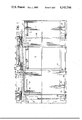
- FIG. 1 is a schematic, partially-sectioned front elevational view of part of a railway or tramway vehicle with double sliding doors according to the invention, showing one door in the open position and the other door in the closed position,
- FIG. 2 is a vertical sectional view taken on arrow II of FIG. 1 with the two doors in the closed position
- FIG. 3 is a view similar to FIG. 2 with the two doors in the open position
- FIG. 4 is a partially cut-away perspective view of the doors seen from inside the vehicle
- FIG. 5 is a vertical sectional view taken on the line V--V of FIG. 1, and
- FIG. 6 is a vertical sectional view taken on the line VI--VI of FIG. 1.
- part of a railway or tramway vehicle is indicated V and has a floor P, an upper wall S and a side F in which an aperture 10 constituting a doorway is formed.
- Two opposing doors 12 are movable simultaneously relative to the doorway 10 between a closed position illustrated in FIGS. 2 and 4 and the left-hand part of FIG. 1, in which they are close together and emplaced in the doorway 10, and an open position illustrated in FIG. 3 and in the right-hand part of FIG. 1, in which they are withdrawn from the doorway 10 and spaced from each other, being located parallel to the portions of the side F adjacent the sides of the doorway 10.
- Each door 12 is constituted by a rectangular panel to the inner face of which is fixed, starting from the outer edge adjacent the upper edge, a profiled guide 14.
- each panel 12 Along the lower edge of each panel 12 is a channel-section guide 16 surmounted by a sealing lip 18 disposed in sealing contact with the facing edge of the floor P of the vehicle V.
- each panel 12 Close to the inner edge of each panel 12 are fixed an upper arm 20 and a lower cranked arm 22 projecting inwardly of the vehicle V respectively beneath the upper wall S and beneath the floor P.
- Each upper arm 20 has a substantially horizontal part 24 and a substantially vertical part 26 which projects upwardly; as is clearly seen in FIGS. 2 and 3, the length of the part 24 of the arm 20 associated with the right-hand door 12 is greater than the part 24 of the arm 20 associated with the left-hand door 12, for reasons which will be explained below.
- the parts 24 of the two upper arms 20 carry respective roller guide members 28 which engage a pair of upper guides 30 carried by the upper wall S and angled outwardly towards the side edges of the doorway 10.
- the free ends of the two lower arms 22 carry respective roller guide members 32 inserted in corresponding lower guides 34 attached beneath the floor B and located parallel to the upper guides 30.
- Two vertical shafts 36 are located adjacent the side edges of the doorway 10 and are rotatable in respective bushes 38, 40 supported by the upper wall S and the floor P of the vehicle V.
- a horizontal, outwardly-projecting arm 42 is fixed at the lower end of each shaft 36 and carries at its free end a roller guide member 44 which engages the lower guide 16 of the respective door 12.
- each shaft 36 carries an arm 46 which is generally bent into essentially a V-shape; the arms are disposed as mirror images relative to the middle of the doorway 10.
- Each arm 46 has, in fact, a portion 48 fixed to the shaft 36 and a portion 50 bent relative to the portion 48 and carrying a guide carriage 52 at its free end, which engages the upper guide 14 of the respective door 12.
- the portions 48 of the two arms 46 have projections 54 carrying two feeler rollers 56 which engage respective arcuate guide tracks 58 formed in a pair of wheels 60 rotatable about vertical pins 62 carried by the upper wall S close to the tops of the shafts 36.
- the arcuate tracks 58 have similar configurations defined by an initial portion 64 in the form of an arc of a spiral and a final portion 66 in the form of an arc of a circle.
- the portion 64 in the form of an arc of a spiral is disposed towards the exterior, that is, close to the periphery of the wheel 60, while the track 58 of the wheel 60 associated with the left-hand door has its portion 64 in the form of an arc of a spiral situated more towards the interior, that is, towards the centre of the wheel 60.
- the wheels 60 In the closed position of the two doors 12, the wheels 60, with their tracks 58 and the arms 46, are located in the position illustrated in FIG. 2 with the feeler rollers 56 disposed in correspondence with the initial ends of the spiral arcuate portions 64 of the two tracks 58.
- the rotation of the two wheels 60 is achieved by means of an endless chain transmission 68 (in the example illustrated there are two) which passes over respective gear wheels 70, with elongate teeth, coaxial with the wheels 60.
- the chains 68 also run on two idle sprockets 72 so as to take up the configuration illustrated in FIGS. 2 to 4, in which they have a left-hand portion 68a parallel to the angled guides 30, 34 associated with the left-hand door 12, and an opposite right-hand portion 68b parallel to the guides 30, 34 associated with the right-hand door 12.
- the free end of the vertical portion 26 of the upper arm 20 fixed to the left-hand door 12 is fixed to the portion 68a, while the free end of the vertical portion 26 of the arm 20 fixed to the right-hand door 12 is fixed to the portion 68b.
- the movement of the chains 68 is effected by means of a single pressurised-fluid jack 74 supported by the upper wall S of the vehicle, the rod 76 of which is fixed at 78 to the initial ends of the portions 68a of these chains.
- the jack 74 In the closed position of the two doors 12, the jack 74 is in the contracted condition illustrated in FIGS. 2 and 4.
- the jack 74 is extended by means of a conventional pressurised-fluid circuit, not illustrated, so as to move the portions 68a and 68b of the chains 68 in the direction indicated by the arrows F.
- the movement of the chains 68 causes simultaneously the movement of the upper arms 20 of the two panels 12 in opposite directions and the clockwise rotation of the two wheels 60.
- the two panels 12 then start to move away from each other while, simultaneously, the two arms 46 move angularly with their respective vertical shafts 36 as a result of the cooperation between the feeler rollers 56 and the arcuate tracks 58.
- the feeler rollers 56 pass over the initial spiral arcuate portions 64, whereby the panels 12 are displaced angularly outwardly of the doorway 10 due to the cooperation between the guide carriages 52 carried by the arms 46 and the upper guides 14 as the panels 12 proceed in their sliding movements away from each other along the guides 30 and 34.
- the lower parts of the panels 12 are accompanied by the arms 42 driven by the vertical shafts 36 and cooperating with the lower guide 16.
- the feeler rollers 56 pass over the final circular arcuate portions 66 of the two tracks 58 and the arms 46 then accompany the sliding of the panels 12 during the phase of the full extension of the jack 74 to the open position illustrated in FIG. 3.
Landscapes
- Engineering & Computer Science (AREA)
- Mechanical Engineering (AREA)
- Wing Frames And Configurations (AREA)
- Power-Operated Mechanisms For Wings (AREA)
- Support Devices For Sliding Doors (AREA)
- Special Wing (AREA)
- Securing Of Glass Panes Or The Like (AREA)
- Specific Sealing Or Ventilating Devices For Doors And Windows (AREA)
Applications Claiming Priority (2)
| Application Number | Priority Date | Filing Date | Title |
|---|---|---|---|
| IT67704/83A IT1203828B (it) | 1983-06-28 | 1983-06-28 | Porta a due battenti scorrevoli particolarmente per veicoli ferrotranviari |
| IT67704A/83 | 1983-06-28 |
Publications (1)
| Publication Number | Publication Date |
|---|---|
| US4543746A true US4543746A (en) | 1985-10-01 |
Family
ID=11304643
Family Applications (1)
| Application Number | Title | Priority Date | Filing Date |
|---|---|---|---|
| US06/608,186 Expired - Fee Related US4543746A (en) | 1983-06-28 | 1984-05-08 | Sliding double doors, particularly for railway and tramway vehicles |
Country Status (5)
| Country | Link |
|---|---|
| US (1) | US4543746A (it) |
| EP (1) | EP0130153B1 (it) |
| AT (1) | ATE31341T1 (it) |
| DE (1) | DE3468055D1 (it) |
| IT (1) | IT1203828B (it) |
Cited By (14)
| Publication number | Priority date | Publication date | Assignee | Title |
|---|---|---|---|---|
| US5142823A (en) * | 1989-06-02 | 1992-09-01 | Kiekert Gmbh | Swinging-sliding door for vehicles |
| US5222838A (en) * | 1991-07-19 | 1993-06-29 | Jack Kennedy Metal Products And Buildings | Power mine door system |
| US5240349A (en) * | 1991-07-19 | 1993-08-31 | Jack Kennedy Metal Products And Buildings, Inc. | Power mine door system |
| US5345877A (en) * | 1992-07-10 | 1994-09-13 | Thyssen Industrie Ag | Junction for neighboring car bodies of a track-bound vehicle, especially of a magnetic levitation train, having cable connected doors |
| US5441005A (en) * | 1993-03-19 | 1995-08-15 | Freeman Marine Equipment, Inc. | Closure latching mechanism |
| US5542213A (en) * | 1994-10-27 | 1996-08-06 | Freeman Marine Equipment, Inc. | Sliding marine closure |
| US6032416A (en) * | 1998-06-18 | 2000-03-07 | Westinghouse Air Brake Company | Transit vehicle door |
| US6385910B1 (en) * | 1996-07-24 | 2002-05-14 | Pieter Smink | Swivel-sliding door system for a vehicle |
| US6386601B1 (en) | 1998-09-01 | 2002-05-14 | Elisha Technologies Co Llc | Latching mechanism |
| US20030188488A1 (en) * | 2000-11-21 | 2003-10-09 | Johan Carlsson | Vehicle door operating mechanism |
| EP1584535A1 (de) * | 2004-04-10 | 2005-10-12 | Fahrzeugtechnik Dessau AG - Railroad Technologies - | Schwenkschiebetür für Schienenfahrzeuge |
| US20100072868A1 (en) * | 2008-09-19 | 2010-03-25 | Anvil Construction, Incorporated | Cabinet door system |
| US20140020299A1 (en) * | 2011-03-10 | 2014-01-23 | Nabtesco Corporation | Plug door device |
| US20140215757A1 (en) * | 2011-09-30 | 2014-08-07 | Wabtec Holding Corp. | Base plate structure for transit doors |
Families Citing this family (1)
| Publication number | Priority date | Publication date | Assignee | Title |
|---|---|---|---|---|
| ES2034538T3 (es) * | 1988-09-14 | 1993-04-01 | Inventio Ag | Accionamiento de puerta basculante para vehiculos. |
Citations (3)
| Publication number | Priority date | Publication date | Assignee | Title |
|---|---|---|---|---|
| US1916480A (en) * | 1929-03-28 | 1933-07-04 | Dahlstrom Metallic Door Compan | Entrance inclosure door actuating mechanism |
| US3994094A (en) * | 1974-12-20 | 1976-11-30 | Socimi Societa Costruzioni Industriali Milano S.P.A. | Sliding-wing door for vehicles |
| US4091570A (en) * | 1974-12-10 | 1978-05-30 | Faiveley S.A. | Oblique-displacement sliding door |
Family Cites Families (2)
| Publication number | Priority date | Publication date | Assignee | Title |
|---|---|---|---|---|
| GB1548928A (en) * | 1975-12-20 | 1979-07-18 | Westinghouse Brake & Signal | Sliding plug door mechanisms |
| IN156879B (it) * | 1980-09-04 | 1985-11-30 | Westinghouse Brake & Signal |
-
1983
- 1983-06-28 IT IT67704/83A patent/IT1203828B/it active
-
1984
- 1984-05-08 US US06/608,186 patent/US4543746A/en not_active Expired - Fee Related
- 1984-05-28 EP EP84830164A patent/EP0130153B1/en not_active Expired
- 1984-05-28 AT AT84830164T patent/ATE31341T1/de not_active IP Right Cessation
- 1984-05-28 DE DE8484830164T patent/DE3468055D1/de not_active Expired
Patent Citations (3)
| Publication number | Priority date | Publication date | Assignee | Title |
|---|---|---|---|---|
| US1916480A (en) * | 1929-03-28 | 1933-07-04 | Dahlstrom Metallic Door Compan | Entrance inclosure door actuating mechanism |
| US4091570A (en) * | 1974-12-10 | 1978-05-30 | Faiveley S.A. | Oblique-displacement sliding door |
| US3994094A (en) * | 1974-12-20 | 1976-11-30 | Socimi Societa Costruzioni Industriali Milano S.P.A. | Sliding-wing door for vehicles |
Cited By (24)
| Publication number | Priority date | Publication date | Assignee | Title |
|---|---|---|---|---|
| US5142823A (en) * | 1989-06-02 | 1992-09-01 | Kiekert Gmbh | Swinging-sliding door for vehicles |
| US5222838A (en) * | 1991-07-19 | 1993-06-29 | Jack Kennedy Metal Products And Buildings | Power mine door system |
| US5240349A (en) * | 1991-07-19 | 1993-08-31 | Jack Kennedy Metal Products And Buildings, Inc. | Power mine door system |
| US5345877A (en) * | 1992-07-10 | 1994-09-13 | Thyssen Industrie Ag | Junction for neighboring car bodies of a track-bound vehicle, especially of a magnetic levitation train, having cable connected doors |
| US5441005A (en) * | 1993-03-19 | 1995-08-15 | Freeman Marine Equipment, Inc. | Closure latching mechanism |
| US5549068A (en) * | 1993-03-19 | 1996-08-27 | Freeman Marine Equipment, Inc. | Closure latching mechanism |
| US5848575A (en) * | 1993-03-19 | 1998-12-15 | Freeman Marine Equipment, Inc. | Closure latching mechanism |
| US5542213A (en) * | 1994-10-27 | 1996-08-06 | Freeman Marine Equipment, Inc. | Sliding marine closure |
| US6385910B1 (en) * | 1996-07-24 | 2002-05-14 | Pieter Smink | Swivel-sliding door system for a vehicle |
| US6032416A (en) * | 1998-06-18 | 2000-03-07 | Westinghouse Air Brake Company | Transit vehicle door |
| US6705651B2 (en) | 1998-09-01 | 2004-03-16 | Elisha Holding Llc | Latching mechanism |
| US6386601B1 (en) | 1998-09-01 | 2002-05-14 | Elisha Technologies Co Llc | Latching mechanism |
| US20030188488A1 (en) * | 2000-11-21 | 2003-10-09 | Johan Carlsson | Vehicle door operating mechanism |
| US6792717B2 (en) * | 2000-11-21 | 2004-09-21 | Hubner Gmbh | Vehicle door operating mechanism |
| EP1584535A1 (de) * | 2004-04-10 | 2005-10-12 | Fahrzeugtechnik Dessau AG - Railroad Technologies - | Schwenkschiebetür für Schienenfahrzeuge |
| US20050235564A1 (en) * | 2004-04-10 | 2005-10-27 | Fahrzeugtechnik Dessau Ag | Swinging sliding door for rail vehicles |
| US7426803B2 (en) | 2004-04-10 | 2008-09-23 | Fahrzeugtechnik Dessau Ag | Swinging and sliding door for rail vehicles |
| US20100072868A1 (en) * | 2008-09-19 | 2010-03-25 | Anvil Construction, Incorporated | Cabinet door system |
| US20140020299A1 (en) * | 2011-03-10 | 2014-01-23 | Nabtesco Corporation | Plug door device |
| US9316030B2 (en) | 2011-03-10 | 2016-04-19 | Nabtesco Corporation | Door opening and closing apparatus |
| US9403422B2 (en) * | 2011-03-10 | 2016-08-02 | Nabtesco Corporation | Plug door device |
| US9797171B2 (en) * | 2011-03-10 | 2017-10-24 | Nabtesco Corporation | Plug door device |
| US20140215757A1 (en) * | 2011-09-30 | 2014-08-07 | Wabtec Holding Corp. | Base plate structure for transit doors |
| US9010023B2 (en) * | 2011-09-30 | 2015-04-21 | Wabtec Holding Corp. | Base plate structure for transit doors |
Also Published As
| Publication number | Publication date |
|---|---|
| EP0130153A2 (en) | 1985-01-02 |
| IT1203828B (it) | 1989-02-23 |
| EP0130153A3 (en) | 1986-01-22 |
| EP0130153B1 (en) | 1987-12-09 |
| IT8367704A0 (it) | 1983-06-28 |
| ATE31341T1 (de) | 1987-12-15 |
| DE3468055D1 (en) | 1988-01-21 |
Similar Documents
| Publication | Publication Date | Title |
|---|---|---|
| US4543746A (en) | Sliding double doors, particularly for railway and tramway vehicles | |
| US5461829A (en) | Trolley rail system for sliding door | |
| US4785582A (en) | Method and device for regulating vehicle door window | |
| DE3249091C2 (de) | Hochziehbare Jalousie | |
| US4474405A (en) | Tilt-sliding roof for motor vehicles | |
| US5921611A (en) | Upwardly retracting vehicle door | |
| US2651541A (en) | Vertically movable vehicle door structure | |
| US5362122A (en) | Vehicle roof | |
| US2215363A (en) | Retractable automobile top | |
| DE1505744A1 (de) | Einrichtung zum Abdichten,insbesondere von Schiebefenstern an Kraftfahrzeugen | |
| EP1176280B1 (de) | Tor, insbesondere Garagentor | |
| US5421395A (en) | Swinging-and-sliding door for vehicles, especially mass-transit vehicles | |
| US6145254A (en) | Retractable roof panel | |
| US2228439A (en) | Window operator | |
| CN114165142A (zh) | 智控全自动多扇折叠门 | |
| US4186523A (en) | Skylight operating means | |
| DE4033691C2 (de) | Seitenwandanordnung für gedeckte Kastenaufbauten | |
| DE4242937C1 (de) | Antrieb für eine Bogenschiebetür | |
| FR2442328A1 (fr) | Dispositif automatique pour portes a panneaux | |
| DE2950564C2 (de) | Hallendach mit Schiebedachelementen | |
| US3501865A (en) | Door operating mechanism | |
| KR200244033Y1 (ko) | 차량장착용 가동식 덮개장치 | |
| JPH0421703Y2 (it) | ||
| JPH0724261Y2 (ja) | 車両用自動開閉扉のチェーンガイドレールの構造 | |
| CN220451741U (zh) | 一种入口铁艺门 |
Legal Events
| Date | Code | Title | Description |
|---|---|---|---|
| AS | Assignment |
Owner name: FIAT FERROVIARIA SAVIGLIANO S.P.A. 14, VIA MAGENTA Free format text: ASSIGNMENT OF ASSIGNORS INTEREST.;ASSIGNOR:RACCA, CARLO;REEL/FRAME:004259/0256 Effective date: 19840410 |
|
| REMI | Maintenance fee reminder mailed | ||
| LAPS | Lapse for failure to pay maintenance fees | ||
| STCH | Information on status: patent discontinuation |
Free format text: PATENT EXPIRED DUE TO NONPAYMENT OF MAINTENANCE FEES UNDER 37 CFR 1.362 |
|
| FP | Lapsed due to failure to pay maintenance fee |
Effective date: 19891001 |