US4570849A - Fan drive, particularly for cooling installation of vehicles - Google Patents
Fan drive, particularly for cooling installation of vehicles Download PDFInfo
- Publication number
- US4570849A US4570849A US06/672,206 US67220684A US4570849A US 4570849 A US4570849 A US 4570849A US 67220684 A US67220684 A US 67220684A US 4570849 A US4570849 A US 4570849A
- Authority
- US
- United States
- Prior art keywords
- control
- valve
- fan drive
- pressure
- drive according
- Prior art date
- Legal status (The legal status is an assumption and is not a legal conclusion. Google has not performed a legal analysis and makes no representation as to the accuracy of the status listed.)
- Expired - Fee Related
Links
- 238000009434 installation Methods 0.000 title claims abstract description 11
- 238000001816 cooling Methods 0.000 title claims abstract description 9
- 238000004804 winding Methods 0.000 claims description 3
- 239000007788 liquid Substances 0.000 claims 2
- 239000002826 coolant Substances 0.000 claims 1
- 230000008901 benefit Effects 0.000 description 6
- 239000000498 cooling water Substances 0.000 description 6
- 230000010354 integration Effects 0.000 description 3
- 230000001105 regulatory effect Effects 0.000 description 3
- 238000010276 construction Methods 0.000 description 2
- 238000010616 electrical installation Methods 0.000 description 2
- 230000007257 malfunction Effects 0.000 description 2
- 230000009467 reduction Effects 0.000 description 2
- 125000006850 spacer group Chemical group 0.000 description 2
- 230000004323 axial length Effects 0.000 description 1
- 230000008859 change Effects 0.000 description 1
- 230000006835 compression Effects 0.000 description 1
- 238000007906 compression Methods 0.000 description 1
- 230000003247 decreasing effect Effects 0.000 description 1
- 230000018109 developmental process Effects 0.000 description 1
- 238000010586 diagram Methods 0.000 description 1
- 238000006073 displacement reaction Methods 0.000 description 1
- 230000000694 effects Effects 0.000 description 1
- 239000012530 fluid Substances 0.000 description 1
- 230000002706 hydrostatic effect Effects 0.000 description 1
- 230000003116 impacting effect Effects 0.000 description 1
- 239000002184 metal Substances 0.000 description 1
- 238000000034 method Methods 0.000 description 1
- 238000001208 nuclear magnetic resonance pulse sequence Methods 0.000 description 1
- 230000008569 process Effects 0.000 description 1
- 238000010008 shearing Methods 0.000 description 1
- XLYOFNOQVPJJNP-UHFFFAOYSA-N water Substances O XLYOFNOQVPJJNP-UHFFFAOYSA-N 0.000 description 1
Images


Classifications
-
- F—MECHANICAL ENGINEERING; LIGHTING; HEATING; WEAPONS; BLASTING
- F01—MACHINES OR ENGINES IN GENERAL; ENGINE PLANTS IN GENERAL; STEAM ENGINES
- F01P—COOLING OF MACHINES OR ENGINES IN GENERAL; COOLING OF INTERNAL-COMBUSTION ENGINES
- F01P7/00—Controlling of coolant flow
- F01P7/02—Controlling of coolant flow the coolant being cooling-air
- F01P7/04—Controlling of coolant flow the coolant being cooling-air by varying pump speed, e.g. by changing pump-drive gear ratio
- F01P7/044—Controlling of coolant flow the coolant being cooling-air by varying pump speed, e.g. by changing pump-drive gear ratio using hydraulic drives
Definitions
- the invention relates to a fan drive which comprises a hydraulic motor, a control valve which regulates the flow of pressure medium through a bypass around the hydraulic motor as a function of the temperature, a control valve, a control spring which biases the control piston in the direction of closing the bypass, a control pressure in the control chamber which also acts on the control piston in the direction of closing the bypass, and a pilot valve which regulates the control pressure and which is actuated by an electromechanical servo element.
- Another object of the present invention is to provide a fan drive which eliminates unnecessary operation of the fan or its running at excessively high rotational speeds so that energy savings may be achieved.
- Another object of the present invention is to provide a fan drive which does not require an oil leakage line, i.e., to provide a fan drive suited for gear motors or other drives not requiring oil leakage lines, or for connecting a series of drives.
- Another object of the present invention is to provide a fan drive in which electrical power is required only for changing the settings.
- a further object of the present invention is to provide a fan drive with the highest degree of integration possible.
- Another object of the invention is to ensure that the fan motor will continue to operate independently of the temperature in case of a malfunction of the electrical installation.
- a fan drive particularly for a cooling installation of a rail vehicle, comprising a hydraulic motor which is actuated by a pressure medium; a bypass for detouring the flow of pressure medium around the hydraulic motor; control valve which regulates the flow of pressure medium to the bypass and to the hydraulic motor, this control valve comprising a control piston for opening and closing the bypass and having a central bore, an insert upon which the central bore of the control piston is slidingly arranged so as to form a seal, a front surface of the control piston facing the direction of closing the bypass which is acted upon by the pressure medium, a back surface of the control piston facing away from the direction of closing the bypass which is also acted upon by the pressure medium wherein the pressure acting on the front side of the control piston is the full pressure of the pressure medium called the high-pressure, and the pressure of the pressure medium acting on the back side of the control piston is called the control pressure, a control spring for biasing the control piston in the direction of closing the bypass, and a
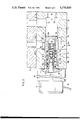
- FIG. 1 shows a block circuit diagram of a control circuit according to the present invention
- FIG. 2 shows a motor connector plate with an integrated control valve in the form of a seat valve
- FIG. 3 shows a control valve in the form of a slide valve
- FIG. 4 shows an alternative embodiment with reference to FIG. 2.
- control valve of the fan drive consists of simple parts that may be produced inexpensively and installed readily and in that, as the result of the placement of a pilot control valve within a control piston, very little installation space is required.
- the control valve makes possible a regulation which reacts rapidly to even slight variations of the reference value.
- the fan drive according to the invention is suitable for different hydrostatic drives, particularly also for the fans of electric traction motors. By means of the regulated fan drive and the sensitive controls, the unnecessary operation of the fan and/or its running at excessively high rotational speed are prevented. This leads to a substantial savings of energy.
- a preferred further development of the invention comprises supporting a control spring on an insert piece, with an end away from a control piston. In this manner, a separate fastening of the insert piece is not necessary, because the insert piece is held on a wall section of the electromechanical servo component by a pretensioning of the spring.
- a control valve which regulates the bypass is appropriately in the form of a seat valve, in which the surface area of a control piston exposed to an advancing pressure is equal to the surface area exposed to a control pressure. This configuration results in an extremely short structural length.
- a variant of an embodiment of the present invention comprises a control valve in the form of a slide valve which regulates the bypass. In this case as well, the surface areas exposed to a advancing pressure and the control pressure are equal. In order to create this ratio of surface areas in the case of a slide valve, it is advisable that the center bore extend over the entire axial length of the control piston and that the insert piece protrude through said bore.
- a further substantial advantage of the invention is that an oil leakage line is not necessary.
- the surfaces exposed to a back pressure in the opening or closing direction of the control valve, respectively are counterbalanced. Because it is not necessary for the pressure medium to escape from the pilot valve to an oil leakage line, but may pass directly to the return line, the control valve is particularly suited for gear motors or other drivers not requiring oil leakage lines, or for connecting a series of drives.
- a control magnet or a step motor may be provided as the electromechanical servo component.
- the use of a step motor has the advantage that electric power is required only for changing the settings.
- the pilot valve comprises essentially a valve cone, a valve seat and a spring loading the valve cone.
- the tip of the valve cone interacts with a ball, whereby the valve cone may be lifted from the valve seat.
- the spring force biasing the valve cone of the pilot valve is adjustable.
- a regulating screw or a fixable support element which may be slidably introduced into any desired position may be provided for adjustment. The latter has the advantage that during the installation of the pilot valve the force of the spring may be measured, thereby eliminating subsequent adjustments.
- control piston and the pilot valve may be arranged in a connector plate of the hydraulic motor.
- the pilot valve In order to insure that the fan motor will keep on operating independently of the cooling temperature in case of a malfunction of the electrical installation, it is advantageous for the pilot valve to assume its closed position when an electronic circuit of the elecromechanical servo element, respectively, is without current.
- FIG. 1 shows a radiator 1 with tanks 2 and 3, associated with an axial fan 4.
- the axial fan 4 is located on a shaft 5 of a hydraulic motor 6.
- the hydraulic motor 6 is a gear motor, connected with a high-pressure carrying advance line 7 and a back-pressure carrying return line 8 of a hydraulic circuit.
- a spring loaded check valve 13 is inserted in a bypass line 11, 12. The switching with the chokes 34 and 46 and the mode of operation of the check valve 13 shall be explained in detail below with reference to FIGS. 2 and 4.
- a pilot valve 14, activated by an electromechanical servo element 15 is provided for actuating the check valve 13. On the outlet side, the valves 13 and 14 are connected with the return line 8.
- the electromechanical servo element 15 is connected with the outlet terminal of an electronic controller 17 by means of a control line 16.
- a temperature sensor 19, located in a water tank 3 of a radiator 1 is connected with the inlet terminals of the controller 17 by means of control lines 18.
- the temperature sensor 19 When the temperature of the cooling water of the radiator 1 is very low, the temperature sensor 19 has a low electrical resistivity so that the electronic controller 17 receives a high input signal. This results in a corresponding current or pulse sequence being passed to the electromechanical servo element 15 in order to bring the armature of the electromechanical servo element 15 into the proper position.
- the pilot valve 14 is thereby placed into its open position, and the compression forces acting on the check valve 13 are affected in such a manner that the resulting pressure force overcomes the force of the control spring in the opening direction of the valve.
- the bypass line 11, 12 is thus connected.
- the fan motor 6 is thereby bridged by the bypass line 11, 12 so that the flow of the pressure medium in the advance line 7 affects the fan motor 6 not at all or only slightly.
- the resistance characteristic of the temperature sensor 19 also changes as the cooling water is increasingly heated, resulting in a change in the input value of the electronic controller 17.
- the output signal of the electronic controller 17 changes correspondingly, resulting in an effect on the electromechanical servo element 15.
- the pilot valve 14 is thus set at a smaller passage cross section. This setting of the pilot valve 14 affects the pressure conditions at the valve closing element of the check valve 13 in such a manner that the passage cross-section of the valve 13 is also reduced.
- the proportion of the pressure medium stream impacting the fan motor 6 increases.
- the fan motor 6 thus drives the axial fan 4 at a corresponding rotational speed.
- the input signal of the electronic cotroller 17 becomes so small as a result of the high resistance value of the temperature sensor 19, that the output signal of the controller brings the electromechanical servo element 15 to its end position.
- the pilot valve 14 is thus completely closed.
- equal pressure is built up on both sides of the valve closing element of the check valve 13. This pressure is built-up in the closing direction with a time delay so that the check valve 13 is closed.
- the bypass line 11, 12 is now blocked, the fan motor 6 is subjected to the entire flow of the pressure medium, and the axial fan 4 is operated with a maximum rotational speed.
- the axial fan 4 would be coordinated with an electric machine.
- the temperature sensor 19 is then integrated with the motor winding. The prevailing temperature of the winding determines the position of the pilot valve 14 and thus the rotational speed of the fan as the input valve of the electronic controller 17.
- FIG. 2 shows a connector plate 20 of a hydraulic motor 21.
- the connector plate 20 has a bore 22 which is arranged at right angles to two axially distant bores, a bore 23 carrying high pressure (HD) and a bore 24 carrying a backpressure (RD).
- the connection carrying the high pressure (HD) of the advance line is designated 22a and the connection carrying the backpressure (RD) of the return line is 24a.
- a shoulder 25 is provided in the bore 22 between the bore 23 and the bore 24, the internal radius of which serves as the valve seat 26 of the check valve.
- a control piston 27 is sealingly guided in the bore 22 and rests against the valve seat 26.
- the control piston has an essentially cup-like configuration and defines a control chamber 28 with its side facing away from the valve seat 26.
- the control piston 27 has a stepped central bore 29a, 29b, in which the section 29 forms part of the control chamber 28.
- the radial surface limiting the control chamber 28 is equal to the surface of the control piston 27 which is exposed to the high pressure (HD).
- An insert 30 is guided in a pressure medium-tight manner in the bore section 29b, i.e., the control piston 27 is slidably held on the convex surface of the insert 30.
- the insert 30 has a radial collar 31 supporting one end of a control spring 32, on its end facing away from the control piston 27 and rests against the shoulder of the bore 29a, 29b with its other end.
- the control piston 27 is thereby loaded against the valve seat 26.
- An axial bore 33 with a choke 34 is provided in the control piston 27 outside the bore section 29b. The choke 34 connects the section of the bore 22 located in front of the check valve with the control chamber 28.
- the insert 30 has a central, multistep bore 36, extending over its entire length.
- the end of the bore 36 to the right in FIG. 2 is provided with threads 37, into which a hollow bolt 38 is screwed.
- a spring 39 which loads a valve cone 41 against a valve set 42, is supported against the hollow bolt 38.
- the valve cone 41 and the valve seat 42 form the essential parts of the pilot valve 14.
- the tip of the valve cone 41 is supported against a ball 43 located on the right hand side in the bore 36, and in turn interacts with a tappet 44 of a control magnet 45.
- the electronic controller 17 is structurally integrated with the control magnet 45.
- the section of the bore 36 in which the ball 43 is located and the bore section 29a which is a component of the control chamber 28, are connected with each other by means of a choke 46.
- the choke 46 has the function of preventing the upward motion of the two elastically supported elements, the control piston 27 and valve cone 41.
- the space of the bore section 29b, which is bordered by the insert 30 forms a pressure outlet chamber 47 which is connected by a radial bore 48 with the bore 24 carrying the backpressure (RD).
- the mode of operation of the control valve shown in FIG. 2 shall be described as follows, in which the moving parts of the control valve assume the positions they would have when the overall installation is in a state without pressure and power.
- the pressure medium is then able to flow through the open pilot valve 14 into the outlet chamber 47, and from there through the bore 48 into the return connection 24a.
- the reduction of the pressure in the control chamber 28 leads to the displacement of the control piston 27 against the control spring 32, thereby opening the bypass between the bores 23 and 24.
- the extent to which the passage cross section of the bypass is opened is a function of the opening cross section of the pilot valve 14 which affects the reduction of pressure in the control chamber 28.
- FIG. 3 shows the arrangement of the check valve 13 and the pilot valve 14 in a housing 50.
- the housing may be provided separately or structurally integrated with a hydraulic motor.
- the housing 50 has a bore 51 which is at right angles to two vertically spaced bores, a bore 52 connected with the high pressure (HD) and a bore 53 connected with the backpressure (RD).
- a retainer ring 54 is inserted in the bore 51 and between the bores 52 and 53.
- a substantially annular control piston 55 is guided sealingly in the bore 51.
- the control piston abuts the side of the retainer ring 54 facing the bore 53, and defines a control chamber 28 with its side facing away from the retainer ring 54.
- the radial surface of the control piston 55 bordering the control chamber 28 is equal in size to the surface area exposed to the high pressure (HD).
- the control piston 55 has a stepped center bore 56a, 56b, with the section 56a being part of the control chamber 28.
- An insert 57 is guided in the bore section 56b in a pressure medium-tight manner, i.e., the control piston 55 is slidably supported on the convex surface of the insert 57.
- the insert 57 extends through the entire control piston 55 and protrudes on the high pressure side.
- the insert 57 has a radial collar 58 at its end facing away from the control piston 55.
- the collar 58 lies against a housing of a step motor 59.
- a control spring 32 rests against the radial collar 58 and the shoulder of the bore 56a, 56b, with its other end thereby loads the control piston 56 against the retainer ring 54.
- An axial bore 33 located in the control piston 55 outside the bore section 56b, whereby the part of the bore 51 in front of the check valve with the control chamber 28.
- a stud bolt 60 is screwed into the thread 37.
- a spacer 61 which supports the spring 39, is arranged on the side of the stud bolt facing the pilot valve.
- the spring 39 in turn loads the valve cone 41.
- the spacer 61 is constructed so that it permits the passage of the hydraulic fluid to the radial orifices 62.
- the radial orifices 62 open into an annular space 63 on the circumferential surface of the insert 57.
- the annular space 63 is in turn connected with the bore 53 by means of a radial bore 48 in the control piston 55. As seen in FIG. 3, the control piston 55 has no surface effectively exposed to the backpressure.
- control valve is a slide valve and the electromechanical servo element is a step motor 59.
- FIG. 4 shows a variant of the embodiment of the pilot valve of FIG. 2. Parts that are identical with those in FIG. 2, are signified by identical reference numerals.
- the end of the insert adjacent to the pressure outlet chamber 47 has only an annular groove 64 in place of threads.
- a support element 65 is located in the insert 30.
- the support element 65 comprises a sheet metal cup, the bottom of which supports the spring 39. Several orifices are arranged in the bottom of the support element 65, the total cross section of which is larger than that of the pilot valve 14.
- the support element 65 has a plurality of projections 68 on its cylindrical wall 67. The projections engage the groove 64 of the insert 30.
- the advantage of this arrangement is that the force of the spring 39 acting on the valve cone 41 may be adjusted in a simple manner without any pressure testing during the installation of the pilot valve. Accordingly, the support element 65 is displaced in the direction of the valve cone 41 and the spring 39 is loaded. The force acting on the support element 65 is measured in this manner.
- a plurality of outwardly directed projections 68 is produced by means of appropriate implements, by shearing, for example. Said projections engage the groove 64 of the support element 30. Pressure testing to determine the opening pressure and subsequent adjustment of the spring 39 are not required.
- the pilot valves 14 are in the form of analog valves and are regulated by the electromechanical servo components, e.g., electromagnet 45, and step motor 59.
- the armature or spindle stroke, respectively, of the electrochemical servo components vary as a function of the prevailing output signal of the electronic controller 17. In this manner, when the temperature of the cooling water remains constant over an extended period of time and, therefore, the rotational speed of the fan is kept constant, the pilot valve remains in its position and is not required to perform a multitude of switching processes.
Landscapes
- Engineering & Computer Science (AREA)
- Combustion & Propulsion (AREA)
- Mechanical Engineering (AREA)
- General Engineering & Computer Science (AREA)
- Chemical & Material Sciences (AREA)
- Safety Valves (AREA)
- Fluid-Pressure Circuits (AREA)
- Air-Conditioning For Vehicles (AREA)
- Cooling, Air Intake And Gas Exhaust, And Fuel Tank Arrangements In Propulsion Units (AREA)
- Fluid-Driven Valves (AREA)
- Control Of Electric Motors In General (AREA)
- Control Of Direct Current Motors (AREA)
- Structures Of Non-Positive Displacement Pumps (AREA)
- Control Of Positive-Displacement Air Blowers (AREA)
Applications Claiming Priority (2)
| Application Number | Priority Date | Filing Date | Title |
|---|---|---|---|
| DE3341795 | 1983-11-19 | ||
| DE3341795A DE3341795C2 (de) | 1983-11-19 | 1983-11-19 | Regelventil für eine Regeleinrichtung eines hydraulischen Lüfterantriebs, insbesondere für Kühlanlagen von Schienenfahrzeugen |
Publications (1)
| Publication Number | Publication Date |
|---|---|
| US4570849A true US4570849A (en) | 1986-02-18 |
Family
ID=6214690
Family Applications (1)
| Application Number | Title | Priority Date | Filing Date |
|---|---|---|---|
| US06/672,206 Expired - Fee Related US4570849A (en) | 1983-11-19 | 1984-11-16 | Fan drive, particularly for cooling installation of vehicles |
Country Status (6)
| Country | Link |
|---|---|
| US (1) | US4570849A (de) |
| EP (1) | EP0142713B1 (de) |
| JP (1) | JPS6111499A (de) |
| AT (1) | ATE36375T1 (de) |
| DE (2) | DE3341795C2 (de) |
| ES (1) | ES536409A0 (de) |
Cited By (25)
| Publication number | Priority date | Publication date | Assignee | Title |
|---|---|---|---|---|
| GB2191847A (en) * | 1986-06-17 | 1987-12-23 | Sundstrand Hydratec Ltd | Hydraulically driven engine cooling systems |
| US4794883A (en) * | 1986-11-12 | 1989-01-03 | Toyota Jidosha Kabushiki Kaisha | Dual reservoir tank for propellant hydraulic fluid for internal combustion engine hydraulically driven cooling fan and for power steering actuating fluid |
| US4798050A (en) * | 1986-06-11 | 1989-01-17 | Toyoda Koki Kabushiki Kaisha | Control system for hydraulic tandem pump in motor vehicle |
| US4798177A (en) * | 1986-11-12 | 1989-01-17 | Toyota Jidosha Kabushiki Kaisha | System for controlling rotational speed of hydraulically driven cooling fan of internal combustion engine, responsive to engine coolant and also fan propellant temperature |
| US5284202A (en) * | 1992-04-24 | 1994-02-08 | Ingersoll-Rand Company | Compressor aftercooler apparatus for use in low temperature operations, and method of use |
| US5398794A (en) * | 1993-06-02 | 1995-03-21 | Horton Industries, Inc. | Overheating protection device for rotational control apparatus |
| US5778693A (en) * | 1996-12-20 | 1998-07-14 | Itt Automotive Electrical Systems, Inc. | Automotive hydraulic engine cooling system with thermostatic control by hydraulic actuation |
| EP0821166A3 (de) * | 1996-07-21 | 1999-03-17 | Dürr Dental GmbH & Co. KG | Sicherheitseinrichtung an einer Pumpe |
| US6030314A (en) * | 1998-09-28 | 2000-02-29 | Caterpillar Inc. | Method and apparatus for retarding a work machine having a fluid-cooled brake system |
| US6758266B1 (en) * | 1998-02-27 | 2004-07-06 | Volvo Wheel Loader Ab | Work machine having a hydraulic liquid cooling and heating system |
| US20050079082A1 (en) * | 2001-10-30 | 2005-04-14 | Davide Olivieri | Intake valve for a high-pressure pump, in particular for internal combustion engine fuel |
| US20060086587A1 (en) * | 2004-10-21 | 2006-04-27 | Swanson Craig M | Clutch system |
| US20070062186A1 (en) * | 2005-09-19 | 2007-03-22 | Wuthrich Jerome B | Auxiliary pump for hydrostatic transmission |
| US20080135792A1 (en) * | 2003-12-18 | 2008-06-12 | Jean Armiroli | Hydraulic Slide Valve Provided With a Piezoelectric Washer |
| US7438169B2 (en) | 2004-10-21 | 2008-10-21 | Kit Masters Inc. | Clutch system |
| US20090183963A1 (en) * | 2008-01-18 | 2009-07-23 | Kit Masters Inc. | Clutch Device and Methods |
| US20100122808A1 (en) * | 2008-11-19 | 2010-05-20 | Wabtec Holding Corp. | Temperature Management System for a 2CD Type Air Compressor |
| US20100282562A1 (en) * | 2009-05-07 | 2010-11-11 | Kit Masters Inc. | Clutch systems and methods |
| US8360219B2 (en) | 2010-04-26 | 2013-01-29 | Kit Masters, Inc. | Clutch system and methods |
| US8544627B2 (en) | 2008-11-12 | 2013-10-01 | Horton, Inc. | Two-speed clutch and retro-fit kit |
| US9046137B2 (en) | 2010-01-22 | 2015-06-02 | Kit Masters Inc. | Fan clutch apparatus and methods |
| US20160305093A1 (en) * | 2014-03-31 | 2016-10-20 | Kubota Corporation | Work machine |
| US20180209418A1 (en) * | 2015-10-12 | 2018-07-26 | Yu-Sen J. Chu | Lobe gear pump |
| CN108488079A (zh) * | 2018-02-28 | 2018-09-04 | 重庆酋创科技有限公司 | 用于控制风扇转速的装置 |
| US11499648B2 (en) * | 2019-04-05 | 2022-11-15 | Kerox Ipari Es Kereskedelmi Kft. | Flow controlled piston valve |
Families Citing this family (3)
| Publication number | Priority date | Publication date | Assignee | Title |
|---|---|---|---|---|
| US4738330A (en) * | 1985-03-22 | 1988-04-19 | Nippondenso Co., Ltd. | Hydraulic drive system for use with vehicle power steering pump |
| DE3714842A1 (de) * | 1987-05-05 | 1988-11-17 | Sueddeutsche Kuehler Behr | Luefterantrieb fuer eine kuehlanlage, insbesondere fuer schienenfahrzeuge |
| DE102012102186A1 (de) * | 2012-03-15 | 2013-09-19 | Ihi Charging Systems International Gmbh | Turbine für einen Abgasturbolader |
Citations (11)
| Publication number | Priority date | Publication date | Assignee | Title |
|---|---|---|---|---|
| US2673706A (en) * | 1950-07-28 | 1954-03-30 | Gen Controls Co | Pilot controlled main valve with cushioning means |
| US2758811A (en) * | 1953-01-09 | 1956-08-14 | Edwin W Peterson | Multiple pilot controlled main valve |
| US2893680A (en) * | 1955-01-10 | 1959-07-07 | Phillips Petroleum Co | Valve |
| US3118648A (en) * | 1963-02-20 | 1964-01-21 | American Radiator & Standard | Thermostatic flow control valve |
| US3198204A (en) * | 1963-05-08 | 1965-08-03 | Vapor Corp | Inline valve |
| US3297047A (en) * | 1964-03-17 | 1967-01-10 | Vapor Corp | Valve assembly |
| US3415269A (en) * | 1967-01-24 | 1968-12-10 | Vapor Corp | Multiple positioned pilot controlled poppet valve |
| US3664129A (en) * | 1968-05-08 | 1972-05-23 | Hyster Co | Hydraulic cooling system |
| US4009860A (en) * | 1974-05-18 | 1977-03-01 | Woma-Apparatebau Wolfgang Maasberg & Co. Gmbh | Shutoff valve for high-pressure spray guns |
| US4065052A (en) * | 1976-11-04 | 1977-12-27 | Evans Products Company | Dual action control mechanism |
| US4283009A (en) * | 1980-02-07 | 1981-08-11 | The Bendix Corporation | Control valve for fluid-operated clutch |
Family Cites Families (10)
| Publication number | Priority date | Publication date | Assignee | Title |
|---|---|---|---|---|
| CH326068A (fr) * | 1955-07-05 | 1957-11-30 | Charles Dubois Roger | Vanne électromagnétique |
| GB864659A (en) * | 1957-07-10 | 1961-04-06 | Stanley William Hoskins | Improvements in solenoid-operated fluid-flow control valves |
| US3033228A (en) * | 1959-03-23 | 1962-05-08 | Lewis K Rimer | Low-force valve control |
| FR1402416A (fr) * | 1964-07-24 | 1965-06-11 | Suedeeutsche Kuehlerfabrik Jul | Soupape commandée thermostatiquement |
| DE1550321B2 (de) * | 1966-11-12 | 1972-07-27 | Fa. Hans Schiedrum, 4000 Düsseldorf-Eller | Druckventil mit elektrischem antrieb |
| US3540540A (en) * | 1968-05-08 | 1970-11-17 | Hyster Co | Cooling system for lift trucks |
| US3799497A (en) * | 1972-04-20 | 1974-03-26 | Control Concepts | Two stage solenoid operated valve |
| DE2525240A1 (de) * | 1975-06-06 | 1976-12-23 | Bosch Gmbh Robert | Vorsteuerbares ventil fuer hydraulische anlagen |
| US4073464A (en) * | 1976-08-24 | 1978-02-14 | Chemetron Corporation | Cylinder valve for gas fire extinguishing system |
| DE3222851C1 (de) * | 1982-06-18 | 1991-07-25 | Süddeutsche Kühlerfabrik Julius Fr. Behr GmbH & Co KG, 7000 Stuttgart | Luefterantrieb fuer eine Kuehlanlage,insbesondere fuer Schienenfahrzeuge |
-
1983
- 1983-11-19 DE DE3341795A patent/DE3341795C2/de not_active Expired
-
1984
- 1984-10-01 ES ES536409A patent/ES536409A0/es active Granted
- 1984-10-17 DE DE8484112506T patent/DE3473321D1/de not_active Expired
- 1984-10-17 EP EP84112506A patent/EP0142713B1/de not_active Expired
- 1984-10-17 AT AT84112506T patent/ATE36375T1/de active
- 1984-10-18 JP JP59217507A patent/JPS6111499A/ja active Pending
- 1984-11-16 US US06/672,206 patent/US4570849A/en not_active Expired - Fee Related
Patent Citations (11)
| Publication number | Priority date | Publication date | Assignee | Title |
|---|---|---|---|---|
| US2673706A (en) * | 1950-07-28 | 1954-03-30 | Gen Controls Co | Pilot controlled main valve with cushioning means |
| US2758811A (en) * | 1953-01-09 | 1956-08-14 | Edwin W Peterson | Multiple pilot controlled main valve |
| US2893680A (en) * | 1955-01-10 | 1959-07-07 | Phillips Petroleum Co | Valve |
| US3118648A (en) * | 1963-02-20 | 1964-01-21 | American Radiator & Standard | Thermostatic flow control valve |
| US3198204A (en) * | 1963-05-08 | 1965-08-03 | Vapor Corp | Inline valve |
| US3297047A (en) * | 1964-03-17 | 1967-01-10 | Vapor Corp | Valve assembly |
| US3415269A (en) * | 1967-01-24 | 1968-12-10 | Vapor Corp | Multiple positioned pilot controlled poppet valve |
| US3664129A (en) * | 1968-05-08 | 1972-05-23 | Hyster Co | Hydraulic cooling system |
| US4009860A (en) * | 1974-05-18 | 1977-03-01 | Woma-Apparatebau Wolfgang Maasberg & Co. Gmbh | Shutoff valve for high-pressure spray guns |
| US4065052A (en) * | 1976-11-04 | 1977-12-27 | Evans Products Company | Dual action control mechanism |
| US4283009A (en) * | 1980-02-07 | 1981-08-11 | The Bendix Corporation | Control valve for fluid-operated clutch |
Cited By (49)
| Publication number | Priority date | Publication date | Assignee | Title |
|---|---|---|---|---|
| US4798050A (en) * | 1986-06-11 | 1989-01-17 | Toyoda Koki Kabushiki Kaisha | Control system for hydraulic tandem pump in motor vehicle |
| GB2191847A (en) * | 1986-06-17 | 1987-12-23 | Sundstrand Hydratec Ltd | Hydraulically driven engine cooling systems |
| GB2191847B (en) * | 1986-06-17 | 1990-03-28 | Sundstrand Hydratec Ltd | Hydraulically driven engine cooling systems |
| US4794883A (en) * | 1986-11-12 | 1989-01-03 | Toyota Jidosha Kabushiki Kaisha | Dual reservoir tank for propellant hydraulic fluid for internal combustion engine hydraulically driven cooling fan and for power steering actuating fluid |
| US4798177A (en) * | 1986-11-12 | 1989-01-17 | Toyota Jidosha Kabushiki Kaisha | System for controlling rotational speed of hydraulically driven cooling fan of internal combustion engine, responsive to engine coolant and also fan propellant temperature |
| US5284202A (en) * | 1992-04-24 | 1994-02-08 | Ingersoll-Rand Company | Compressor aftercooler apparatus for use in low temperature operations, and method of use |
| US5398794A (en) * | 1993-06-02 | 1995-03-21 | Horton Industries, Inc. | Overheating protection device for rotational control apparatus |
| EP0821166A3 (de) * | 1996-07-21 | 1999-03-17 | Dürr Dental GmbH & Co. KG | Sicherheitseinrichtung an einer Pumpe |
| US5778693A (en) * | 1996-12-20 | 1998-07-14 | Itt Automotive Electrical Systems, Inc. | Automotive hydraulic engine cooling system with thermostatic control by hydraulic actuation |
| US6758266B1 (en) * | 1998-02-27 | 2004-07-06 | Volvo Wheel Loader Ab | Work machine having a hydraulic liquid cooling and heating system |
| US6030314A (en) * | 1998-09-28 | 2000-02-29 | Caterpillar Inc. | Method and apparatus for retarding a work machine having a fluid-cooled brake system |
| US20050079082A1 (en) * | 2001-10-30 | 2005-04-14 | Davide Olivieri | Intake valve for a high-pressure pump, in particular for internal combustion engine fuel |
| US7296980B2 (en) | 2001-10-30 | 2007-11-20 | Centro Studi Componenti Per Veicoli S.P.A. | Intake valve for a high-pressure pump, in particular for internal combustion engine fuel |
| US7954785B2 (en) * | 2003-12-18 | 2011-06-07 | Borgwarner Inc. | Hydraulic slide valve provided with a piezoelectric washer |
| US20080135792A1 (en) * | 2003-12-18 | 2008-06-12 | Jean Armiroli | Hydraulic Slide Valve Provided With a Piezoelectric Washer |
| US7533764B2 (en) | 2004-10-21 | 2009-05-19 | Kit Masters Inc. | Clutch system |
| US20060086587A1 (en) * | 2004-10-21 | 2006-04-27 | Swanson Craig M | Clutch system |
| US20070137974A1 (en) * | 2004-10-21 | 2007-06-21 | Kit Masters Inc. | Clutch System and Method |
| US9086102B2 (en) | 2004-10-21 | 2015-07-21 | Kit Masters Inc. | Clutch system |
| US7311189B2 (en) | 2004-10-21 | 2007-12-25 | Kit Masters Inc. | Clutch system and method |
| US20080029362A1 (en) * | 2004-10-21 | 2008-02-07 | Kit Masters Inc. | Clutch System and Method |
| US20060254873A1 (en) * | 2004-10-21 | 2006-11-16 | Kit Masters Inc., A Minnesota Corporation | Clutch system |
| US7438169B2 (en) | 2004-10-21 | 2008-10-21 | Kit Masters Inc. | Clutch system |
| US20090014273A1 (en) * | 2004-10-21 | 2009-01-15 | Kit Masters Inc. | Clutch System |
| US7104382B2 (en) | 2004-10-21 | 2006-09-12 | Kit Masters Inc. | Clutch system |
| US8522944B2 (en) | 2004-10-21 | 2013-09-03 | Kit Masters Inc. | Clutch system |
| US20090236196A1 (en) * | 2004-10-21 | 2009-09-24 | Kit Masters Inc. | Clutch system and method |
| US7604106B2 (en) | 2004-10-21 | 2009-10-20 | Kit Masters Inc. | Clutch system |
| US7201267B2 (en) | 2004-10-21 | 2007-04-10 | Kit Masters Inc. | Clutch system and method |
| US20100038205A1 (en) * | 2004-10-21 | 2010-02-18 | Kit Masters Inc. | Clutch System |
| US20070062186A1 (en) * | 2005-09-19 | 2007-03-22 | Wuthrich Jerome B | Auxiliary pump for hydrostatic transmission |
| US7640735B2 (en) * | 2005-09-19 | 2010-01-05 | Parker-Hannifin Corporation | Auxiliary pump for hydrostatic transmission |
| US20090183963A1 (en) * | 2008-01-18 | 2009-07-23 | Kit Masters Inc. | Clutch Device and Methods |
| US8100239B2 (en) | 2008-01-18 | 2012-01-24 | Kit Masters Inc. | Clutch device and methods |
| US9140309B2 (en) | 2008-11-12 | 2015-09-22 | Horton, Inc. | Two-speed clutch and kit |
| US8544627B2 (en) | 2008-11-12 | 2013-10-01 | Horton, Inc. | Two-speed clutch and retro-fit kit |
| US20100122808A1 (en) * | 2008-11-19 | 2010-05-20 | Wabtec Holding Corp. | Temperature Management System for a 2CD Type Air Compressor |
| US8128379B2 (en) | 2008-11-19 | 2012-03-06 | Wabtec Holding Corp. | Temperature management system for a 2CD type air compressor |
| US20100282562A1 (en) * | 2009-05-07 | 2010-11-11 | Kit Masters Inc. | Clutch systems and methods |
| US8109375B2 (en) | 2009-05-07 | 2012-02-07 | Kit Masters Inc. | Clutch systems and methods |
| US9133889B2 (en) | 2010-01-22 | 2015-09-15 | Kit Masters Inc. | Fan clutch apparatus and methods |
| US9046137B2 (en) | 2010-01-22 | 2015-06-02 | Kit Masters Inc. | Fan clutch apparatus and methods |
| US8360219B2 (en) | 2010-04-26 | 2013-01-29 | Kit Masters, Inc. | Clutch system and methods |
| US20160305093A1 (en) * | 2014-03-31 | 2016-10-20 | Kubota Corporation | Work machine |
| US10006188B2 (en) * | 2014-03-31 | 2018-06-26 | Kubota Corporation | Work machine |
| US20180209418A1 (en) * | 2015-10-12 | 2018-07-26 | Yu-Sen J. Chu | Lobe gear pump |
| US10995751B2 (en) * | 2015-10-12 | 2021-05-04 | Pmc Liquiflo Equipment Co., Inc. | Lobe gear pump with inducer assembly and centrifugal pump having one fluid flow path |
| CN108488079A (zh) * | 2018-02-28 | 2018-09-04 | 重庆酋创科技有限公司 | 用于控制风扇转速的装置 |
| US11499648B2 (en) * | 2019-04-05 | 2022-11-15 | Kerox Ipari Es Kereskedelmi Kft. | Flow controlled piston valve |
Also Published As
| Publication number | Publication date |
|---|---|
| DE3341795A1 (de) | 1985-05-30 |
| JPS6111499A (ja) | 1986-01-18 |
| ES8600467A1 (es) | 1985-10-16 |
| EP0142713B1 (de) | 1988-08-10 |
| ES536409A0 (es) | 1985-10-16 |
| DE3341795C2 (de) | 1986-07-10 |
| EP0142713A2 (de) | 1985-05-29 |
| EP0142713A3 (en) | 1986-09-10 |
| DE3473321D1 (en) | 1988-09-15 |
| ATE36375T1 (de) | 1988-08-15 |
Similar Documents
| Publication | Publication Date | Title |
|---|---|---|
| US4570849A (en) | Fan drive, particularly for cooling installation of vehicles | |
| US12516683B2 (en) | Pressure-compensation hydraulic pump, rotation speed control system and control method, and construction machinery | |
| US4550693A (en) | Temperature control arrangement for combustion engine | |
| EP1790855B1 (de) | Hydraulisches Pumpensystem mit variablen Durchsatz und Druck | |
| US4522334A (en) | Thermostatic control device | |
| KR970001931A (ko) | 내연기관용 연료공급장치 및 이를 조절하는 방법 | |
| DE102004018955A1 (de) | Steuerungsverfahren für eine extern steuerbare Lüfterkupplung | |
| DE69805253T2 (de) | Verfahren zur Steuerung der Leerlaufdrehzahl einer Brennkraftmaschine | |
| JPH01299800A (ja) | 複動液圧シリンダの駆動制御のための液圧制御装置 | |
| JP2581789B2 (ja) | 液圧駆動装置 | |
| EP0097230B1 (de) | Lüfterantrieb für eine Kühlanlage, insbesondere für Schienenfahrzeuge | |
| KR970022195A (ko) | 냉각탑에서의 냉각팬용 유압 구동 제어 시스템 | |
| US5778924A (en) | Hydraulic control valve block | |
| EP0781923A4 (de) | Kapauitätsregelung für hydraulische pumpe mit veränderlicher fördermenge | |
| EP0484049A1 (de) | Durch Strömungskraft gesteuertes Entladeventil | |
| RU2610364C2 (ru) | Гидростатическое приводное устройство | |
| JP2000054817A (ja) | 内燃機関の潤滑回路の油圧制御装置 | |
| US5118259A (en) | System for controlling oil viscosity | |
| KR20060051550A (ko) | 솔레노이드 밸브 제어 장치 | |
| JPS60173324A (ja) | 分配型燃料噴射ポンプの燃料温度制御装置 | |
| JP2003129818A (ja) | 油圧制御装置 | |
| SU1666667A1 (ru) | Гидропривод землеройной машины | |
| WO2014122665A1 (en) | Fan-drive control for open circuit variable displacement pump | |
| KR19980076619A (ko) | 차량엔진의 온도감응 솔레노이드 isc밸브 | |
| JPS62215182A (ja) | 電磁式圧力制御弁 |
Legal Events
| Date | Code | Title | Description |
|---|---|---|---|
| AS | Assignment |
Owner name: SUEDDEUTSCHE KUEHLERFABRIK JULIUS FR. BEHR GMBH & Free format text: ASSIGNMENT OF ASSIGNORS INTEREST.;ASSIGNORS:KLAUCKE, THOMAS;PIGISCH, FRANZ;REEL/FRAME:004336/0006;SIGNING DATES FROM 19841102 TO 19841105 Owner name: SUEDDEUTSCHE KUEHLERFABRIK JULIUS FR. BEHR GMBH & Free format text: ASSIGNMENT OF ASSIGNORS INTEREST;ASSIGNORS:KLAUCKE, THOMAS;PIGISCH, FRANZ;SIGNING DATES FROM 19841102 TO 19841105;REEL/FRAME:004336/0006 |
|
| FEPP | Fee payment procedure |
Free format text: PAYER NUMBER DE-ASSIGNED (ORIGINAL EVENT CODE: RMPN); ENTITY STATUS OF PATENT OWNER: LARGE ENTITY Free format text: PAYOR NUMBER ASSIGNED (ORIGINAL EVENT CODE: ASPN); ENTITY STATUS OF PATENT OWNER: LARGE ENTITY |
|
| FEPP | Fee payment procedure |
Free format text: PAYOR NUMBER ASSIGNED (ORIGINAL EVENT CODE: ASPN); ENTITY STATUS OF PATENT OWNER: LARGE ENTITY |
|
| FPAY | Fee payment |
Year of fee payment: 4 |
|
| REMI | Maintenance fee reminder mailed | ||
| REMI | Maintenance fee reminder mailed | ||
| LAPS | Lapse for failure to pay maintenance fees | ||
| FP | Lapsed due to failure to pay maintenance fee |
Effective date: 19930220 |
|
| STCH | Information on status: patent discontinuation |
Free format text: PATENT EXPIRED DUE TO NONPAYMENT OF MAINTENANCE FEES UNDER 37 CFR 1.362 |