US4583733A - Baseball bat swing measuring device - Google Patents
Baseball bat swing measuring device Download PDFInfo
- Publication number
- US4583733A US4583733A US06/764,523 US76452385A US4583733A US 4583733 A US4583733 A US 4583733A US 76452385 A US76452385 A US 76452385A US 4583733 A US4583733 A US 4583733A
- Authority
- US
- United States
- Prior art keywords
- sensor unit
- baseball bat
- beams
- receiving
- swing
- Prior art date
- Legal status (The legal status is an assumption and is not a legal conclusion. Google has not performed a legal analysis and makes no representation as to the accuracy of the status listed.)
- Expired - Fee Related
Links
Images


Classifications
-
- A—HUMAN NECESSITIES
- A63—SPORTS; GAMES; AMUSEMENTS
- A63B—APPARATUS FOR PHYSICAL TRAINING, GYMNASTICS, SWIMMING, CLIMBING, OR FENCING; BALL GAMES; TRAINING EQUIPMENT
- A63B69/00—Training appliances or apparatus for special sports
- A63B69/0002—Training appliances or apparatus for special sports for baseball
Definitions
- This invention relates to a swing measuring device for measuring the inclination and height of the swing plane of a baseball bat and the speed of the bat.
- an object of this invention is to provide a swing measuring device which comprises a laser oscillator emitting a laser beam of high directivity provided in a sensor unit similar in configuration to a home plate, and light receiving elements and optical systems for receiving the laser beams reflected from a baseball bat, so that the angle of elevation of the bat and the spped of the bat may be measured in an open area without contacting either the baseball player or the baseball bat.
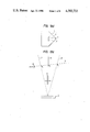
- FIGS. 1(a) and (b) and 2 are diagrams describing the principles of the invention, and, especially, FIG. 2 shows the reflection pattern of a laser beam from a reflective sheet required for determining the height of the swing plane, FIG. 1(c) showing a state in which a measuring device according to the invention is used;
- FIG. 3 is a explanatory diagram showing a light receiving unit having light receiving regions in the form of concentric circles;
- FIG. 4 is a graphic representation indicating the results of calculation in determining the swing height
- FIG. 5 is an explanatory diagram showing the components of a sensor of a swing measuring device according to this invention.
- FIG. 6 is a perspective view showing the arrangement of the components in the sensor
- FIG. 7 is a diagram showing the light receiving signals of three light receiving elements, and a clock pulse train extracted by the light receiving signals.
- FIG. 8 is a block diagram showing the circuit for the sensor.
- FIGS. 1a and 1b are diagrams describing the principles of the invention.
- reference numeral 1 designates a sensor unit in the form of a home plate; 2, a first light transmitting and receiving hole for transmitting a first light beam perpendicular to the sensor unit and for receiving a light beam reflected from the baseball bat; 3, a second light transmitting and receiving hole for transmitting a second light beam, which forms an angle a with the first light beam and is inclined towards the catcher and for receiving a light beam reflected from the baseball bat; and 4, a third light transmitting and receiving hole for transmitting a third light beam inclined by an angle a towards the pitcher in the plane defined by the first and second light beams. Further in FIG.
- reference numeral 5 designates the aforementioned first light beam, 6, the second light beam; 7, the third light beam; and 8, the line of intersection along which the swing plane of a baseball bat intersects the plane defined by the first, second and third light beams 5, 6 and 7.
- the coordinates of the intersections P 1 , P 2 and P 3 of the three light beams 6, 5 and 7 and the line of intersections 8, and the lengths of segments P 1 P 2 , P 2 P 3 and P 1 P 3 are as follows: ##EQU1## Therefore, the ratio (r) of the length of the segment P 1 P 2 to that of the segment P 2 P 3 is: ##EQU2## From Equation (4), ##EQU3## Therefore, if the difference (proportional to the length of segment P 1 P 2 ) between the time when the baseball bat crosses the second light beam 6 and the time when it crosses the first light beam 5, and the difference (proportional to the length of segment P 2 P 3 ) between when it crosses the first light beam 5 and the time when it crosses the third light beam 7 are measured, the ratio r can be obtained. Accordingly, the swing angle ⁇ of
- the speed v is obtained by dividing the segment length P 1 P 3 by the difference ⁇ t between the time when the baseball bat crosses the second light beam 6 and the time when it crosses the third light beam 7. Therefore, if the height h' of the baseball bat swing plane is known, the values ⁇ and ⁇ t can be used to obtain the speed v as follows: ##EQU4##
- a reflective sheet which is prepared by arranging a number of ball lenses made of transparent material of high refractive index in the form of a flat plate is bonded to a baseball bat with thermally active adhesive.
- the reflected light beam exhibits a reflective characteristic as shown in FIG. 2.
- This reflective sheet is "Scotch" light marked high intensity grade reflective sheet 2870, which is manufactured by the 3M company. Therefore, if a light receiving unit 9 (FIG. 3) having two coaxial light receiving regions is used to perfrom the following calculation with respect to the output signals S 1 and S 2 of the light receiving regions, the calculated result H is determined with respect to h' between h' 1 and h' 2 . The distance between the light receiving unit and the reflex sheet, can be determined, so that the height of the baseball bat swing plane may be determined.
- the radius of the inner light receiving region 10 is one-half of the radius of the outside diameter of the outer light receiving region 11.
- FIG. 5 is a top view showing the optical components, electrical components and a laser oscillator of the sensor unit 1.
- reference numeral 12 designates the laser oscillator; 13, total reflection mirrors; and 14, the output laser beam of the laser oscillator.
- FIG. 6 is a perspective view showing the components of the sensor unit 1.
- reference numeral 15 designates a first beam split cube for reflecting a part of the incident laser beam 14 vertically upwardly of the sensor unit 1 and for transmitting the beam reflected from the reflective sheet on the baseball bat to the concentric-circle-shaped light receiving unit 9; 16, filters for transmitting only the laser beam from the laser oscillator; and 17, a first lens for condensing the laser beam reflected from the baseball bat.
- the light receiving unit 9 is positioned nearer to the first beam split cube 15 than the rear focal point of the first lens 17.
- reference numeral 18 designates a second beam split cube for reflecting a part of the incident laser beam obliquely upwardly to form the second laser beam and for transmitting the laser beam reflected from the reflective sheet; 19, second and third lenses for applying the reflected beams to second and third light receiving elements 20 and 21, respectively; and 22, a third beam split cube for forming the third laser beam.
- reference numeral 23 designates the light receiving signal of the inner region 10 of the concentric-circle-shaped light receiving unit 9; 24, the light receiving signal of the outer region 11; 25, the light receiving signal of the second light receiving element 20; 26, the light receiving signal of the third light receiving element 21; and 27, a clock pulse train which is selected by the light receiving signals 25 and 26 of the second and third light receiving elements 20 and 21.
- the sensor unit 1 is constructed as described above. Therefore, the three parameters respecting the baseball bat swing plane, namely, the height, speed and inclination can be determined from expressions (5), (6) and (7) as described before. A specific method of processing the signals will not be described in detail herein; however, the calculation of expressions (5) through (7) is carried out using a digital computer in a known fashion as follows.
- FIG. 8 is a block diagram showing the connection and construction of the signal processor for the swing measuring device with which the invention is concerned.
- reference numeral 28 denotes the inner region of the first light receiving unit; 29, the outer region of the first light receiving region; 30 and 31, the second and third light receiving units; 32, a preamplifier, 33, waveform shaping circuit; 34, a gate circuit, 35, a clock signal generator; 36, a counter for counting the number of the pulses of the pulse train of the clock signal determined by the gate circuit 34; 37, a sample hold circuit for holding the maximum value of a reflection signal obtained out of the inner and outer regions of the first light receiving unit; and 38, a digital processor for calculating the value of r on the basis of the outputs of the two counter circuits 36 and the two sample holding circuits 37 in accordance with the above-described expression (4), a swing angle ⁇ by using the given data a and the calculated value of r, a swing height h' from the relationship between H and h' shown in FIG. 4
Landscapes
- Health & Medical Sciences (AREA)
- General Health & Medical Sciences (AREA)
- Physical Education & Sports Medicine (AREA)
- Length Measuring Devices By Optical Means (AREA)
- Testing Or Calibration Of Command Recording Devices (AREA)
Applications Claiming Priority (2)
| Application Number | Priority Date | Filing Date | Title |
|---|---|---|---|
| JP57-113549 | 1982-06-30 | ||
| JP57113549A JPS596077A (ja) | 1982-06-30 | 1982-06-30 | スウイング測定器 |
Related Parent Applications (1)
| Application Number | Title | Priority Date | Filing Date |
|---|---|---|---|
| US06509503 Continuation | 1983-06-30 |
Publications (1)
| Publication Number | Publication Date |
|---|---|
| US4583733A true US4583733A (en) | 1986-04-22 |
Family
ID=14615116
Family Applications (1)
| Application Number | Title | Priority Date | Filing Date |
|---|---|---|---|
| US06/764,523 Expired - Fee Related US4583733A (en) | 1982-06-30 | 1985-08-12 | Baseball bat swing measuring device |
Country Status (2)
| Country | Link |
|---|---|
| US (1) | US4583733A (ja) |
| JP (1) | JPS596077A (ja) |
Cited By (17)
| Publication number | Priority date | Publication date | Assignee | Title |
|---|---|---|---|---|
| WO1989003710A1 (en) * | 1987-10-26 | 1989-05-05 | Innovative Training Products, Inc. | Start system batting unit |
| US4979745A (en) * | 1988-02-26 | 1990-12-25 | Maruman Golf Co. Ltd. | Electric apparatus for use when practicing a golf swing |
| US5118102A (en) * | 1989-04-19 | 1992-06-02 | Bahill Andrew T | Bat selector |
| US5634855A (en) * | 1995-06-07 | 1997-06-03 | King; James A. | Portable golf club swing speed indicator with downward angled collimated light sensors |
| US5988861A (en) * | 1995-12-06 | 1999-11-23 | Baum Research & Development Co., Inc. | Sports implement testing methods and apparatus |
| US6091355A (en) * | 1998-07-21 | 2000-07-18 | Speed Products, Inc. | Doppler radar speed measuring unit |
| US6640200B1 (en) | 1995-12-06 | 2003-10-28 | Charles S. Baum | Sports implement testing methods and apparatus |
| US20060189418A1 (en) * | 2005-02-23 | 2006-08-24 | Shigehiro Kawai | Deviation measuring apparatus |
| US7775914B1 (en) | 2008-02-15 | 2010-08-17 | Qlb, Llc | Baseball swing training device |
| US20110183786A1 (en) * | 2010-01-27 | 2011-07-28 | Sung-Jen Chen | Sensing home plate |
| US20140206480A1 (en) * | 2013-01-22 | 2014-07-24 | Spessard Manufacturing, Llc | Electronic home plate for baseball and softball games and method for automatic determination of presence, position and speed of a ball relative to the strike zone |
| US8911309B1 (en) | 2011-08-17 | 2014-12-16 | John Harihar | Batting sleeve sensor systems |
| US20150258402A1 (en) * | 2014-03-13 | 2015-09-17 | About 52 Feet Llc | Baseball batting trainer |
| US10670723B2 (en) | 2014-11-04 | 2020-06-02 | University Of Maryland, College Park | Projectile position measurement using non-linear curve fitting |
| US10874932B1 (en) | 2019-09-26 | 2020-12-29 | Balance Bike, LLC | Batting tee targeting apparatus |
| USD956587S1 (en) | 2018-09-20 | 2022-07-05 | Catalyst Sports Llc | Movement measurement device housing |
| US11491369B2 (en) * | 2018-09-20 | 2022-11-08 | Catalyst Sports Llc | Bat speed measuring device |
Citations (6)
| Publication number | Priority date | Publication date | Assignee | Title |
|---|---|---|---|---|
| US3117451A (en) * | 1960-12-05 | 1964-01-14 | Bat O Matic Inc | Batter's swing analyzing apparatus |
| GB1190564A (en) * | 1966-06-01 | 1970-05-06 | Hilger & Watts Ltd | Method of and Means for Surface Measurement. |
| US4150825A (en) * | 1977-07-18 | 1979-04-24 | Wilson Robert F | Golf game simulating apparatus |
| US4306722A (en) * | 1980-08-04 | 1981-12-22 | Rusnak Thomas L | Golf swing training apparatus |
| US4367009A (en) * | 1977-01-21 | 1983-01-04 | Canon Kabushiki Kaisha | Optical scanning apparatus with beam splitter to provide plural light beams |
| US4461477A (en) * | 1982-06-14 | 1984-07-24 | Stewart Eddie A | Method and apparatus for improving the performance of a batter |
-
1982
- 1982-06-30 JP JP57113549A patent/JPS596077A/ja active Pending
-
1985
- 1985-08-12 US US06/764,523 patent/US4583733A/en not_active Expired - Fee Related
Patent Citations (6)
| Publication number | Priority date | Publication date | Assignee | Title |
|---|---|---|---|---|
| US3117451A (en) * | 1960-12-05 | 1964-01-14 | Bat O Matic Inc | Batter's swing analyzing apparatus |
| GB1190564A (en) * | 1966-06-01 | 1970-05-06 | Hilger & Watts Ltd | Method of and Means for Surface Measurement. |
| US4367009A (en) * | 1977-01-21 | 1983-01-04 | Canon Kabushiki Kaisha | Optical scanning apparatus with beam splitter to provide plural light beams |
| US4150825A (en) * | 1977-07-18 | 1979-04-24 | Wilson Robert F | Golf game simulating apparatus |
| US4306722A (en) * | 1980-08-04 | 1981-12-22 | Rusnak Thomas L | Golf swing training apparatus |
| US4461477A (en) * | 1982-06-14 | 1984-07-24 | Stewart Eddie A | Method and apparatus for improving the performance of a batter |
Cited By (20)
| Publication number | Priority date | Publication date | Assignee | Title |
|---|---|---|---|---|
| WO1989003710A1 (en) * | 1987-10-26 | 1989-05-05 | Innovative Training Products, Inc. | Start system batting unit |
| US4979745A (en) * | 1988-02-26 | 1990-12-25 | Maruman Golf Co. Ltd. | Electric apparatus for use when practicing a golf swing |
| US5118102A (en) * | 1989-04-19 | 1992-06-02 | Bahill Andrew T | Bat selector |
| US5634855A (en) * | 1995-06-07 | 1997-06-03 | King; James A. | Portable golf club swing speed indicator with downward angled collimated light sensors |
| US5988861A (en) * | 1995-12-06 | 1999-11-23 | Baum Research & Development Co., Inc. | Sports implement testing methods and apparatus |
| US6640200B1 (en) | 1995-12-06 | 2003-10-28 | Charles S. Baum | Sports implement testing methods and apparatus |
| US6091355A (en) * | 1998-07-21 | 2000-07-18 | Speed Products, Inc. | Doppler radar speed measuring unit |
| US20060189418A1 (en) * | 2005-02-23 | 2006-08-24 | Shigehiro Kawai | Deviation measuring apparatus |
| US7775914B1 (en) | 2008-02-15 | 2010-08-17 | Qlb, Llc | Baseball swing training device |
| US8043175B2 (en) * | 2010-01-27 | 2011-10-25 | Sung-Jen Chen | Sensing home plate |
| US20110183786A1 (en) * | 2010-01-27 | 2011-07-28 | Sung-Jen Chen | Sensing home plate |
| US8911309B1 (en) | 2011-08-17 | 2014-12-16 | John Harihar | Batting sleeve sensor systems |
| US20140206480A1 (en) * | 2013-01-22 | 2014-07-24 | Spessard Manufacturing, Llc | Electronic home plate for baseball and softball games and method for automatic determination of presence, position and speed of a ball relative to the strike zone |
| US9352208B2 (en) * | 2013-01-22 | 2016-05-31 | University Of Maryland, College Park | Electronic home plate for baseball and softball games and method for automatic determination of presence, position and speed of a ball relative to the strike zone |
| US20150258402A1 (en) * | 2014-03-13 | 2015-09-17 | About 52 Feet Llc | Baseball batting trainer |
| US9833675B2 (en) * | 2014-03-13 | 2017-12-05 | About 52 Feet, LLC | Baseball batting trainer |
| US10670723B2 (en) | 2014-11-04 | 2020-06-02 | University Of Maryland, College Park | Projectile position measurement using non-linear curve fitting |
| USD956587S1 (en) | 2018-09-20 | 2022-07-05 | Catalyst Sports Llc | Movement measurement device housing |
| US11491369B2 (en) * | 2018-09-20 | 2022-11-08 | Catalyst Sports Llc | Bat speed measuring device |
| US10874932B1 (en) | 2019-09-26 | 2020-12-29 | Balance Bike, LLC | Batting tee targeting apparatus |
Also Published As
| Publication number | Publication date |
|---|---|
| JPS596077A (ja) | 1984-01-13 |
Similar Documents
| Publication | Publication Date | Title |
|---|---|---|
| US4583733A (en) | Baseball bat swing measuring device | |
| US4577863A (en) | Swing measuring device | |
| US5626526A (en) | Golf training device having a two-dimensional, symmetrical optical sensor net | |
| US5110202A (en) | Spatial positioning and measurement system | |
| US4770527A (en) | Photoelectric-piezoelectric velocity and impact sensor | |
| US4652121A (en) | Moving body measuring instrument | |
| KR870002135B1 (ko) | 기록 광비임 촛점 상태 모니터 방법 및 장치 | |
| US4306723A (en) | Golf swing training apparatus | |
| SU1382410A3 (ru) | Оптический датчик с автоматической системой регулировани объектива | |
| US4629885A (en) | Scanning apparatus | |
| US5727789A (en) | Arrow location apparatus | |
| JPH07253462A (ja) | 距離測定装置 | |
| JPS6232950B2 (ja) | ||
| JPH11230699A (ja) | 弾丸の標的到達位置計測装置 | |
| JPS6488304A (en) | Measuring instrument using optical system | |
| JPH0654940A (ja) | 飛翔球体計測装置 | |
| RU1778514C (ru) | Прибор дл измерени диаметров изделий | |
| SU1539525A1 (ru) | Способ измерени положени объекта и устройство дл его осуществлени | |
| SU953457A1 (ru) | Оптико-электронное измерительное устройство | |
| JP2688931B2 (ja) | 光波距離計 | |
| JPH1183488A (ja) | プリズムを備えた測量用ポール | |
| GB2348489A (en) | Location of arrows in a target | |
| JPS59156673U (ja) | スウイング測定装置 | |
| JPS6022297B2 (ja) | ボ−ルの速度及びストライク・ゾ−ンの検出装置 | |
| JP2606731B2 (ja) | 速度測定装置 |
Legal Events
| Date | Code | Title | Description |
|---|---|---|---|
| AS | Assignment |
Owner name: MITSUBISHI DENKI KABUSHIKI KAISHA, NO. 2-3, MARUNO Free format text: ASSIGNMENT OF ASSIGNORS INTEREST.;ASSIGNORS:ITO, SHO;NAKAGUCHI, TOMOYUKI;KASAHARA, KUMIO;AND OTHERS;REEL/FRAME:004506/0400 Effective date: 19830624 |
|
| FEPP | Fee payment procedure |
Free format text: PAYOR NUMBER ASSIGNED (ORIGINAL EVENT CODE: ASPN); ENTITY STATUS OF PATENT OWNER: LARGE ENTITY |
|
| FPAY | Fee payment |
Year of fee payment: 4 |
|
| REMI | Maintenance fee reminder mailed | ||
| FEPP | Fee payment procedure |
Free format text: PAYOR NUMBER ASSIGNED (ORIGINAL EVENT CODE: ASPN); ENTITY STATUS OF PATENT OWNER: LARGE ENTITY Free format text: PAYER NUMBER DE-ASSIGNED (ORIGINAL EVENT CODE: RMPN); ENTITY STATUS OF PATENT OWNER: LARGE ENTITY |
|
| LAPS | Lapse for failure to pay maintenance fees | ||
| FP | Lapsed due to failure to pay maintenance fee |
Effective date: 19940705 |
|
| STCH | Information on status: patent discontinuation |
Free format text: PATENT EXPIRED DUE TO NONPAYMENT OF MAINTENANCE FEES UNDER 37 CFR 1.362 |