US4586835A - Printer for printing characters in two alternative print qualities - Google Patents
Printer for printing characters in two alternative print qualities Download PDFInfo
- Publication number
- US4586835A US4586835A US06/695,997 US69599785A US4586835A US 4586835 A US4586835 A US 4586835A US 69599785 A US69599785 A US 69599785A US 4586835 A US4586835 A US 4586835A
- Authority
- US
- United States
- Prior art keywords
- printing
- character
- character data
- data elements
- Prior art date
- Legal status (The legal status is an assumption and is not a legal conclusion. Google has not performed a legal analysis and makes no representation as to the accuracy of the status listed.)
- Expired - Lifetime
Links
Images


Classifications
-
- G—PHYSICS
- G06—COMPUTING OR CALCULATING; COUNTING
- G06K—GRAPHICAL DATA READING; PRESENTATION OF DATA; RECORD CARRIERS; HANDLING RECORD CARRIERS
- G06K15/00—Arrangements for producing a permanent visual presentation of the output data, e.g. computer output printers
- G06K15/02—Arrangements for producing a permanent visual presentation of the output data, e.g. computer output printers using printers
- G06K15/10—Arrangements for producing a permanent visual presentation of the output data, e.g. computer output printers using printers by matrix printers
-
- G—PHYSICS
- G06—COMPUTING OR CALCULATING; COUNTING
- G06K—GRAPHICAL DATA READING; PRESENTATION OF DATA; RECORD CARRIERS; HANDLING RECORD CARRIERS
- G06K2215/00—Arrangements for producing a permanent visual presentation of the output data
- G06K2215/0002—Handling the output data
- G06K2215/004—Generic data transformation
- G06K2215/006—Anti-aliasing raster data
Definitions
- the present invention relates to printers of the type which are capable of printing characters in two alternative qualities of print and to methods of printing characters in two alternative qualities of print.
- a printer it is desirable for a printer to be able to print characters in more than one quality of print, possibly at more than one speed, in order to provide, for example, a high speed of printing with a low quality of printed character and a low speed of printing with a high quality of printed character.
- Printing at a high speed with a low quality of printed character is commonly performed when a large volume of output is required, as in a data processing environment.
- a high quality of printed character is needed, for example in the printing of letters, and any associated reduction in speed is acceptable.
- each character is formed by printing selected character elements, for example dot elements, in a matrix of print positions arranged in rows and columns
- a high speed of printing is achieved by printing only a comparatively small number of character elements resulting in the printing of characters in a low quality.
- additional character elements are printed in selected print positions in the matrix.
- the positions for the additional character elements are selected so as to provide for enhancement of each character in the horizontal, vertical and diagonal directions by selectively increasing the density of portions of the character.
- the expression "diagonal direction” is used herein to describe any direction which is at an angle to the horizontal and vertical directions.
- a printed character can be described as having high or low print quality in the horizontal direction, the vertical direction and the diagonal direction.
- the object of the present invention is to provide a printer which is capable of printing all required characters in two print qualities without distortion and in which data for printing the characters in a required quality is derived from stored data by an improved method.
- a printer in accordance with the invention prints characters by printing selected character elements in a matrix of print positions arranged in horizontal rows and vertical columns.
- stored sets of character data elements are used to print character elements which form characters.
- Each set of character elements defines the shape of a respective character.
- the stored sets of character data elements are selected so that if a character were to be printed using any one of the stored sets of character data elements the resultant character would have a high print quality in the horizontal direction and a low print quality in the vertical and diagonal directions.
- the printer derives and uses only a subset of the character data elements of each stored set. Each subset is chosen so that the shape of the respective printed character has a low print quality in all directions. Each subset is actually derived by taking all the character data elements of the set and excluding any character data element which, when used for printing, would result in the printing of a character element in a print position which is adjacent in the horizontal direction to a print position in which a character element would previously have been printed. This means that two character elements are not printed side by side. This reduces the density and quality of the character in the horizontal direction. Since the stored character data elements are initially chosen so that any character printed using these data elements will have a low print quality in the vertical and diagonal directions, any character printed using only a subset of character data elements as described above will have a low print quality in all directions.
- the printer performs logical operations on the stored sets of character data elements and detects any data elements which would result in the printing of character elements in two adjacent print positions in the vertical direction or in the diagonal direction. If any such character data elements are detected the printer generates an additional data element which would result in an additional character element being printed in the print position between these two adjacent print positions.
- FIG. 1 illustrates diagrammatically a printer with which the invention may be used
- FIG. 2 illustrates the print head used in the printer of FIG. 1,
- FIG. 3 illustrates how the printer of FIG. 1 performs a printing operation
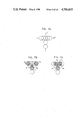
- FIGS. 4a-4c illustrate diagrammatically how stored character data is utilized to provide enhancement in the horizontal direction for higher quality printing in accordance with the invention
- FIGS. 5a-5c illustrate diagrammatically how stored character data is added to in order to provide enhancement in the vertical direction for higher quality printing in accordance with the invention
- FIGS. 6a-6d illustrate diagrammatically a general rule to be applied in adding data to stored data in order to provide enhancement in the diagonal direction for higher quality printing in accordance with the invention
- FIGS. 7a-7c illustrate a situation in which the general rule for enhancement in the diagonal direction is not to be applied
- FIGS. 8a and 8b illustrate two modified forms of the general rule
- FIGS. 9a-9d illustrate further situations in which the general rule for enhancement in the diagonal direction is not to be applied.
- FIG. 10 illustrates possible arrangements of dots in a character
- FIGS. 11a-11g and 12a-12g illustrate various different arrangements of dots used to derive a modified form of the rule for enhancement in the diagonal direction
- FIGS. 13a and 13b illustrate two characters printed in two qualities of printing in accordance with the invention
- FIG. 14 is a diagram of a control circuit for the printer of FIG. 1 used to implement the above principles, and
- FIGS. 15a to 15f are a series of flow charts representing the logical operations to be performed in order to print characters in accordance with the invention.
- the printer includes a platen 1 over which a print medium 2, for example a continuous web of paper, is moved by means of two tractor devices 3,4.
- Each tractor device includes a wheel 5 provided with pins 6 on its outer surface.
- the pins 6 are adapted to engage with holes 7 formed adjacent to the side edges of the medium 2.
- the two wheels 5 are mounted on a common shaft 8 which can be rotated as required by a motor 9 in order to move the medium 2 over the platen 1.
- the printer includes a print head 11 which is mounted on a support 12 extending over the platen 1 so that the medium 2 passes between the platen 1 and the print head 11.
- the print head 11 can be moved along the support 12 by means of a motor 13 by, for example, forming cooperating threads on the support 12 and the head 11 and rotating the support 12.
- the print head can thereby perform printing operations at any point on the surface of the medium 2 as the print head is moved across the medium and the medium is moved over the platen.
- the print head 11 is formed with a row of printing elements 14 supported in a body portion 15, as illustrated in FIG. 2 which is a view of part of the head 11.
- the elements 14 are wires which can be selectively moved axially by, for example, using an electromagnet associated with each one, and which cooperate with an ink ribbon to perform printing operations on the medium.
- Each print element causes the printing of a character element or print dot and as the head moves a matrix of print dots in vertical columns and horizontal rows is printed.
- FIG. 3 which is a plan view of the print head 11 moving over the medium 2
- the row of printing elements 14 moves across the medium 2 in the direction of the arrow and will print a character (H is illustrated) progressively, starting from the left side as viewed in FIG. 3, by printing print dots column by column.
- the elements 14 will be operated selectively so as to print the complete left vertical feature of the character first, then to print the horizontal feature progressively dot by dot and finally to print the complete right vertical feature.
- the size and position of the character and the distance between adjacent dots in the horizontal direction will be controlled by varying the speed of movement of the head in relation to the timing of the operation of the printing elements.
- the spacing of the dots in the vertical direction corresponds to the spacing of the printing elements 14. As illustrated in FIG. 3 the dots printed just touch horizontally and vertically without overlapping.
- FIG. 4 illustrates at 4b a storage device 16 which contains all the character data for printing the character H.
- the storage device 16 has nine columns of data storage locations. Each column has seven binary storage locations and each storage location stores a character data element. As the print head 11 moves across the medium 2 the storage device 16 is read out column by column and the data in each column used to control the row of printing elements 14, each storage location in the column corresponding to one of the printing elements 14. When a binary 1 is stored in a storage location the corresponding printing element will be operated and when a binary 0 is stored the printing element will not be operated.
- FIG. 4b there are nine columns of character data elements. If it is desired to print the character H in low quality print at a high speed only certain of the data elements are used in accordance with the following rule. If two adjacent storage locations, in the horizontal direction, both contain binary 1 data elements, the second binary 1 data element, as viewed in the direction of read out of the storage device, is not used when printing a low quality character. In practice, if the print head 11 is moved across the medium 2 at a speed to print the character in low quality print it is not possible to operate each printing element 14 so that it prints the data elements contained in adjacent columns of the storage device 16. As illustrated in FIG. 4a, the low quality character to be printed is seven print dots high and only five print dots wide.
- the print head 11 is moved at a slow speed and all the character data elements in the storage device 16 are used and the resultant character printed in high quality print as illustrated in FIG. 4c.
- This high quality print character is enhanced as compared with the low quality print character by increasing the density of the printed character elements in the horizontal direction. It will be seen that the speed of movement of the print head is controlled in relation to the timing of the operation of the printing elements so that in the horizontal feature of the character adjacent dots overlap.
- the storage device 16 contains all the character data elements needed for printing the high print quality character illustrated in FIG. 4c at a low speed.
- the low print quality character illustrated in FIG. 4a In order to print the low print quality character illustrated in FIG. 4a at a high speed only a subset of the character data elements are used in accordance with the rule specified. It will be appreciated that, comparing the two forms of character in FIGS. 4a, 4c, the character in FIG. 4c is enhanced only in the horizontal direction by increasing the density of the printed character elements in the horizontal direction. It will further be apparent that only the horizontal feature of the character has been enhanced without affecting the vertical features.
- FIG. 5 illustrates a method of enhancing a character in the vertical direction in order to produce high quality printing.
- the rule to be applied is illustrated in FIG. 5a.
- the print dots for printing one column of a character in low quality print are illustrated at column A. It will be noted that at two places print dots occupy two adjacent print positions.
- additional dots are to be provided between adjacent positions containing dots already so as to increase the density of the printed character elements in the vertical direction.
- the application of the rule results in additional dots being printed between the pairs of dots in positions 3 and 4 and in positions 6 and 7 numbering from the top of the column.
- Column B represents the data elements in the storage device (such as the device 16 in FIG. 4b) which will result in the printing of dots as in column A.
- the data elements in column B are all shifted upward one position (column C) and then the data elements in corresponding positions in columns B and C are ANDed together to produce the additional data elements illustrated in column D.
- These additional elements are used to print additional dots between the pairs of dots in adjacent positions as illustrated in column E, thereby increasing the density of the character data and the printed character elements in the vertical direction.
- the above described enhancement of the character in the vertical direction is performed by two printing operations.
- the low print quality character as in column A is first printed by moving the print head 11 across the medium 2.
- the medium is then moved a distance equal to half the distance between two adjacent printing elements 14.
- the print head 11 is then moved across the medium again and a second printing operation is performed using the additional character data elements illustrated in column D in order to print the additional dots and form the enhanced high print quality character illustrated in column E.
- FIGS. 5b,5c illustrate how the characters H,K respectively can be enhanced in the vertical direction by the above procedure. It will be apparent that only the vertical features of each character are enhanced and no change is made to features extending horizontally or at an angle to the horizontal or vertical.
- FIG. 6 illustrates the rules to be applied for enhancement of a character in the diagonal direction which, as defined above, is any direction which is at an angle to the horizontal and vertical directions.
- FIG. 6a illustrates a "half diagonal" which occurs when the center points of two print dots are spaced apart by one dot width in the vertical direction and by half a dot width in the horizontal direction.
- FIG. 6b illustrates a "full diagonal” which occurs when the center points of two print dots are spaced apart by one dot width in both the vertical and horizontal directions. Dots which are spaced further apart than as in either of these two illustrations are not considered to be joined to form a line in a character and are not taken into consideration in the procedure for enhancement of the character to be described.
- FIGS. 6c and 6d respectively illustrate how portions of a character including half and full diagonals are to be enhanced in accordance with this general rule by inserting additional fill-in print dots between the adjacent dots in the diagonals with center spacing as indicated and thereby increasing the density of the dots or character elements in the diagonal direction.
- FIG. 7a shows a vertical line V intersecting a horizontal line H.
- FIG. 7b shows that, if the general rule is applied, fill-in dots I 1 and I 2 will be inserted between the pairs of dots X 1 Y and X 2 Y forming full diagonals and FIG.
- FIGS. 7b and 7c shows that, if the general rule is applied, fill-in dots I 3 and I 4 will be inserted between the pairs of dots X 3 Y and X 4 Y forming half diagonals.
- fill-in dots I 1 , I 2 and I 3 , I 4 are shown in the separate FIGS. 7b and 7c but it will be appreciated that, if the general rule is applied, all these fill-in dots will be inserted. Insertion of all these fill-in dots will destroy the shape of the character and therefore the general rule is not to be applied in these circumstances.
- FIGS. 8a and 8b An improved rule to be followed in inserting additional fill-in dots between pairs of dots forming half diagonals and full diagonals in order not to destroy the shape of the character when a vertical line intersects a horizontal line can be fully expressed as follows referring to FIGS. 8a and 8b.
- a fill-in dot I will be inserted into a half diagonal AD or BC as illustrated if dot A and dot D are present and neither dot B nor dot C is present or if dot B and dot C are present and neither dot A nor dot D is present.
- This can be represented by the following:
- a fill-in dot I will only be inserted into a full diagonal AF if neither dot B nor dot E is present and will only be inserted into a full diagonal CD if neither dot B nor dot E is present. This can be represented by the following:
- FIG. 9a shows a diagonal line D intersecting the end of a vertical line V in the numeral "1"
- FIG. 9b shows that, if the general rule is applied, fill-in dots I 1 and I 2 will be inserted between the pairs of dots XY 1 and XY 2 forming full diagonals, as well as in other positions. Insertion of fill-in dot I 1 enhances the shape of the serif at the top of the character but insertion of the fill-in dot I 2 destroys the shape of the serif. Fill-in dot I 2 therefore should not be inserted.
- FIG. 9c shows a diagonal line D intersecting the ends of the vertical lines V 1 and V 2 of the character "N"
- FIG. 9d which shows that, if the general rule is applied, fill-in dots I 1 will be inserted between the two pairs of dots XY 1 and fill-in dots I 2 will be inserted between the two pairs of dots XY 2 .
- the insertion of fill-in dots I 1 enhances the shape of the character but insertion of fill-in dots I 2 destroys the shape of the character. Fill-in dots I 2 therefore should not be inserted.
- FIG. 10 which is a modified form of FIG. 8b, illustrates possible arrangements of dots in the region of the intersection of a diagonal line with a vertical line in a character.
- one diagonal line D 1 including dots C and D and another diagonal line D 2 including dots A and F both intersect vertical line V 1 including dots G, A, D and I and vertical line V 2 including dots H, C, F and J. If the lines D 1 and D 2 are true diagonals neither dot B nor dot E will be present.
- FIG. 11a illustrates a diagonal line D 1 including dots C and D not intersecting a vertical line. In this situation (as already described above in connection with FIG. 8b) dots A, I, H and F are not present and a fill-in dot I 1 is to be inserted. In this FIG. 11a and in FIGS. 11b to 11g discussed below it is immaterial whether or not dots G and J are present.
- FIG. 11b illustrates a diagonal line D 1 including dots C and D intersecting the lower end of a vertical line V 2 including dots H and C.
- dots A, I and F are not present and a fill-in dot I 1 is to be inserted.
- FIG. 11c illustrates a diagonal line D 1 including dots C and D intersecting the upper end of a vertical line V 2 including dots C and F.
- dots A, I and H are not present and a fill-in dot I 1 is to be inserted.
- FIG. 11d illustrates a diagonal line D 1 including dots C and D intersecting the middle of a vertical line V 2 including dots H, C and F.
- dots A and I are not present but dots H and F are present and a fill-in dot I 1 is not to be inserted.
- FIG. 11e illustrates a diagonal line D 1 including dots C and D intersecting the lower end of a vertical line V 1 including dots D and I.
- dots A, H and F are not present and a fill-in dot I 1 is to be inserted.
- FIG. 11f illustrates a diagonal line D 1 including dots C and D intersecting the lower end of a vertical line V 1 including dots A and D.
- dots H, F and I are not present and a fill-in dot I 1 is to be inserted.
- FIG. 11g illustrates a diagonal line D 1 including dots C and D intersecting the middle of a vertical line V 1 including dots A, D and I.
- dots H and F are not present but dots A and I are present and a fill-in dot I 1 is not to be inserted.
- FIG. 12a illustrates a diagonal line D 2 including dots A and F not intersecting a vertical line.
- dots G, D, C and J are not present and a fill-in dot I 1 is to be inserted.
- FIG. 12a and in FIGS. 12b to 12g discussed below it is immaterial whether or not dots H and I are present.
- FIG. 12b illustrates a diagonal line D 2 including dots A and F intersecting the lower end of a vertical line V 1 including dots G and A.
- dots C, J and D are not present and a fill-in dot I 1 is to be inserted.
- FIG. 12c illustrates a diagonal line D 2 including dots A and F intersecting the upper end of a vertical line V 1 including dots A and D.
- dots C, J and G are not present and a fill-in dot I 1 is to be inserted.
- FIG. 12d illustrates a diagonal line D 2 including dots A and F intersecting the middle of a vertical line V 1 including dots G, A and D.
- dots C and J are not present but dots G and D are present and a fill-in dot I 1 is not to be inserted.
- FIG. 12e illustrates a diagonal line D 2 including dots A and F intersecting the lower end of a vertical line V 2 including dots F and J.
- dots C, G and D are not present and a fill-in dot I 1 is to be inserted.
- FIG. 12f illustrates a diagonal line D 2 including dots A and F intersecting the lower end of a vertical line V 2 including dots C and F.
- dots G, D and J are not present and a fill-in dot I 1 is to be inserted.
- FIG. 12g illustrates a diagonal line D 2 including dots A and F intersecting the middle of a vertical line V 2 including dots C F and J.
- dots G and D are not present but dots C and J are present and a fill-in dot I 1 is not to be inserted.
- the dots XY 1 correspond to dots C and D in FIG. 11c and therefore a fill-in dot I 1 is to be inserted.
- the dots XY 2 correspond to dots A and F in FIG. 12g and therefore a fill-in dot I 2 is not to be inserted.
- the dots XY 1 at the top of the character correspond to dots A and F in FIG. 12c and therefore a fill-in dot I 1 is to be inserted.
- the dots XY 1 at the bottom of the character correspond to dots A and F in FIG. 12f and therefore a fill-in dot I 1 is to be inserted.
- the dots XY 2 at the top of the character correspond to dots C and D in FIG. 11g and therefore a fill-in dot I 2 is not to be inserted.
- the dots XY 2 at the bottom of the character correspond to dots C and D of FIG. 11d and therefore a fill-in dot I 2 is not to be inserted.
- the first pass prints the character in low quality print and, because the speed is low, all the data elements for horizontal enhancement as illustrated in FIG. 4b are used. Dots are printed at half dot spacing in the horizontal direction resulting in horizontal enhancement by providing dense character elements in the horizontal direction as illustrated in FIG. 4c.
- the above rules are then applied to the data elements in order to provide the additional fill-in dots for vertical and diagonal enhancement.
- the medium is then incremented by one half dot space and the additional dots printed resulting in increasing the density of the character elements in the vertical and diagonal directions.
- FIGS. 13a, 13b illustrate characters H,N respectively printed in a low quality print and in a high quality print after full enhancement in the horizontal, vertical and diagonal directions in accordance with the rules in the above description.
- FIG. 14 illustrates diagrammatically a control circuit for the printer of FIG. 1 which is used to implement the rules for use and enhancement of character data as described above.
- the control circuit includes a control unit 21, a character data storage unit 22, a logic unit 23, a print medium controller 24, a print head actuator unit 25 and a print head movement controller 26.
- the character data for printing all characters is stored in storage unit 22 which is formed with a plurality of storage devices 16. For each character to be printed by the printer, data elements for printing at a low speed with full horizontal enhancement are stored in a corresponding storage device 16 (see FIG. 4b).
- the print medium controller 24 under the control of signals from control unit 21, provides signals to the motor 9 to control the movement of the print medium 2 over the platen and past the print head 11.
- the print head actuator unit 25 provides signals to actuate the printing elements 14 of print head 11 under the control of signals from control unit 21 and in accordance with data signals from data storage unit 22 and from logic unit 23.
- the logic unit 23 performs logical operations on the character data in storage unit 22 and supplies the results to actuator unit 25.
- the control unit 21 controls the flow of data between the data storage unit 22, the logic unit 23 and the print head actuator unit 25.
- the print head movement controller 26 under the control of control unit 21, provides signals to motor 13 to move the print head 11 across the print medium 2.
- control unit 21 controls the supply from storage unit 22 of the character data in each storage device 16 corresponding to a character to be printed but omitting certain data elements in accordance with the first rule defined above with reference to FIG. 4.
- the second binary 1 data element as viewed in the direction of read out of the storage device is omitted resulting in less dense printing of the character elements in the horizontal direction.
- the print head actuator unit 25 produces corresponding signals to the printing elements in head 11 in order to cause printing to occur.
- the control unit 21 also controls the signals applied to motors 9, 13 to cause movement of the print head 11 and print medium 2 as necessary.
- control unit 21 For operation of the printer to print characters at a low speed in a high quality print the control unit 21 first controls the supply to print head actuator unit 26 of all the data in each storage device 16 corresponding to each character to be printed and causes movement of the print head 11 across the print medium to print initially all the character elements needed to print in a low quality, but with enhancement in the horizontal direction as illustrated in FIG. 4c, by printing all the character elements corresponding to the stored data. The control unit 21 then causes movement of the print medium 2 through a distance equal to half the spacing between adjacent printing elements 14. Upon completion of this movement of the medium the control unit 21 causes logic unit 23 to perform the logical operations described with reference to FIG. 5 on the data for each character already printed and to pass to the actuator unit 25 character data corresponding to additional character elements to be printed for enhancement of each character in the vertical direction.
- the logic unit 23 includes devices for detecting the data elements which will result in character elements being printed in adjacent positions in the vertical direction and other devices for generating the additional data elements for providing the fill-in dots.
- the logic unit 23 includes devices for detecting the data elements which will result in character elements being printed in adjacent positions in the diagonal direction and other devices for generating the additional data elements for providing the fill-in dots.
- the logic unit also includes devices for detecting the presence of other data elements and preventing the data elements for fill-in dots being generated when such other data elements are detected.
- control unit 21 causes logic unit 23 to perform the logical operations described with reference to FIGS. 6 to 12 on the data for each character already printed, and to pass to the actuator unit 25 character data corresponding to additional character elements to be printed for enhancement of each character in the diagonal direction.
- control unit 21 causes the print head actuator unit 25 to provide signals for the operation of the printing elements, in accordance with the two sets of additional character data, in a second printing operation at a low speed.
- the result is enhancement of the characters printed in the vertical and diagonal directions as described above by increasing the density of the character elements in these directions.
- each of the printing elements 14 in the head 11 prints a circular dot which has a diameter of 1/60 inch and the spacing between the centers of adjacent elements is equal to the diameter of each dot so that, in the vertical direction, adjacent printed dots will just touch.
- the speed of movement of the head 11 across the print medium 2 and the frequency of operation of the printing elements 14 are chosen so that adjacent columns of dots in the horizontal direction have a spacing of 1/120 inch between centers. As a result, in the horizontal direction, adjacent printed dots overlap by half the diameter of a dot.
- a matrix of 9 columns of dots is used to print each character.
- the character data elements in the corresponding storage device 16 are used but omitting certain data elements in accordance with the rule defined above with reference to FIG. 4.
- two print passes over the medium 2 are used.
- the speed of movement of the head 11 and the frequency of operation of the printing elements 14 are chosen so that adjacent columns of dots in the horizontal direction have a spacing of 1/120 inch between centers providing an overlap as above.
- the print medium 2 is moved a distance of 1/120 inch.
- the speed of movement of the head 11 and the frequency of operation of the printing elements 14 are chosen so that adjacent columns of dots in the horizontal direction have a spacing of 1/120 inch.
- the first print pass dots are printed in a maximum of 9 columns for each character.
- the second print pass dots are printed in a maximum of 17 columns for each character at the higher frequency of operation of the printing elements, so that odd numbered columns of the second print pass coincide with the columns of the first print pass.
- the additional character data for "fill-in" dots generated in accordance with the rules defined above with reference to FIGS. 5 to 12 is used as follows.
- FIG. 15 is a flow chart describing the logical operations which will be performed by the logic unit 23 illustrated in FIG. 14 in order to implement the above principles.
- the logical operations will be performed by suitably programming the microprocessor in accordance with the flow chart of FIG. 15.
- the term COLUMN is used to denote the character data which is suppled to the actuators of the printing elements 14 and the term SLICE is used to denote the character data in the portion of the storage device 16 corresponding to each printing element 14.
- the SLICE data is modified in accordance with the rules established in order to produce the COLUMN data.
- the index i is used to denote the number of the column of dots to be printed.
- A, B, C represent temporary variables.
- ASL2, BSL2, CSL2 represent still further temporary variables each having the value of A, B or C respectively after having been shifted two spaces to the left in accordance with the above rules.
- FIG. 15a is a flow chart of the logical operations which will be performed for printing characters in a low quality at a high speed (data processing) and in general terms represents the following sequence of operations.
- the index is then shifted to column 2.
- FIGS. 15b to 15f are flow charts of the logical operations which will be performed for printing in a high quality at a low speed (word processing) and in general terms represents the following sequence of operations.
- the flow chart of 15b is entered.
- all the character data in the storage device (SLICE) is passed to the print element actuators and used for printing (COLUMN) all of the 9 columns of dots as indicated in box 105.
- the medium 2 will be moved through a distance of 1/120 inch as described above.
- values for ASL, BSL, CSL, ASR, ASL2, CSR and CSL2 are also calculated as indicated in boxes 110, 111, 112, 113, 114, 115, 116 and these values are used to calculate the value of the COLUMN data for each printing element to be used in printing the associated column of dots as indicated in box 117.
- the expression (B ⁇ BSL) represents the generation of additional data for printing vertical fill-in dots in accordance with the rule of FIG. 5 and the remaining expression represents the generation of additional data for printing fill-in dots for "full diagonals" in accordance with the rule of FIGS. 6 to 12.
- values for ASL and BSL are also calculated as indicated in boxes 120 and 121 and these values are used to calculate the value of the COLUMN data for each printing element to be used for printing the associated column of dots as indicated in box 122.
- a variable being calculated includes an inversion (A) and a shift (ASL) of a basic variable the inversion is performed before the shift.
- Each value of COLUMN data calculated from the formula in box 122 represents the generation of additional data for printing fill-in dots for "half diagonals" in accordance with the rule of FIG. 6.
Landscapes
- Physics & Mathematics (AREA)
- Engineering & Computer Science (AREA)
- Mathematical Physics (AREA)
- General Engineering & Computer Science (AREA)
- General Physics & Mathematics (AREA)
- Theoretical Computer Science (AREA)
- Dot-Matrix Printers And Others (AREA)
Priority Applications (8)
| Application Number | Priority Date | Filing Date | Title |
|---|---|---|---|
| US06/695,997 US4586835A (en) | 1984-04-20 | 1985-01-29 | Printer for printing characters in two alternative print qualities |
| CA000477060A CA1220082A (en) | 1984-04-20 | 1985-03-20 | Printer for printing characters in two alternative print qualities |
| DE8585302639T DE3572235D1 (en) | 1984-04-20 | 1985-04-16 | Printer for printing characters in two alternative print qualities |
| EP85302639A EP0159895B1 (de) | 1984-04-20 | 1985-04-16 | Drucker zum Drucken von Zeichen in zwei alternativen Druckqualitäten |
| AU41433/85A AU4143385A (en) | 1984-04-20 | 1985-04-19 | Printing characters in two alternative print qualities |
| ES542408A ES8700155A1 (es) | 1984-04-20 | 1985-04-19 | "una impresora para imprimir caracteres en dos calidades de impresion alternativas" |
| US06/752,176 US4712102A (en) | 1985-01-29 | 1985-07-03 | Method and apparatus for displaying enlarged or enhanced dot matrix characters |
| US06/752,165 US4703323A (en) | 1985-01-29 | 1985-07-03 | Method and apparatus for displaying enhanced dot matrix characters |
Applications Claiming Priority (2)
| Application Number | Priority Date | Filing Date | Title |
|---|---|---|---|
| US60224884A | 1984-04-20 | 1984-04-20 | |
| US06/695,997 US4586835A (en) | 1984-04-20 | 1985-01-29 | Printer for printing characters in two alternative print qualities |
Related Parent Applications (1)
| Application Number | Title | Priority Date | Filing Date |
|---|---|---|---|
| US60224884A Continuation-In-Part | 1984-04-20 | 1984-04-20 |
Related Child Applications (2)
| Application Number | Title | Priority Date | Filing Date |
|---|---|---|---|
| US06/752,176 Continuation-In-Part US4712102A (en) | 1985-01-29 | 1985-07-03 | Method and apparatus for displaying enlarged or enhanced dot matrix characters |
| US06/752,165 Continuation-In-Part US4703323A (en) | 1985-01-29 | 1985-07-03 | Method and apparatus for displaying enhanced dot matrix characters |
Publications (1)
| Publication Number | Publication Date |
|---|---|
| US4586835A true US4586835A (en) | 1986-05-06 |
Family
ID=27084085
Family Applications (1)
| Application Number | Title | Priority Date | Filing Date |
|---|---|---|---|
| US06/695,997 Expired - Lifetime US4586835A (en) | 1984-04-20 | 1985-01-29 | Printer for printing characters in two alternative print qualities |
Country Status (6)
| Country | Link |
|---|---|
| US (1) | US4586835A (de) |
| EP (1) | EP0159895B1 (de) |
| AU (1) | AU4143385A (de) |
| CA (1) | CA1220082A (de) |
| DE (1) | DE3572235D1 (de) |
| ES (1) | ES8700155A1 (de) |
Cited By (15)
| Publication number | Priority date | Publication date | Assignee | Title |
|---|---|---|---|---|
| US4661808A (en) * | 1984-09-28 | 1987-04-28 | Gulton Industries, Inc. | Variable font display |
| US4783667A (en) * | 1987-07-17 | 1988-11-08 | Ncr Canada Ltd - Ncr Canada Ltee | Printing of angled and curved lines using thermal dot matrix printer |
| US4993853A (en) * | 1989-08-11 | 1991-02-19 | International Business Machines Corporation | Matrix character modification information unique to a given font |
| US5078520A (en) * | 1989-03-16 | 1992-01-07 | Fujitsu Limited | Apparatus for driving printing head of wire-dot impact printer |
| EP0351798A3 (de) * | 1988-07-21 | 1992-01-08 | Casio Computer Company Limited | Handabtastdrucker |
| US5086481A (en) * | 1989-03-04 | 1992-02-04 | Brother Kogyo Kabushiki Kaisha | Apparatus for converting outline data into dot data, having means for assuring continuity of visible representations reproduced by the dot data |
| US5167459A (en) * | 1989-03-16 | 1992-12-01 | Fujitsu Limited | Apparatus for driving printing head of wire-dot impact printer |
| US5185818A (en) * | 1991-06-05 | 1993-02-09 | Adobe Systems Incorporated | Method of substituting fonts and displaying characters |
| EP0582433A1 (de) * | 1992-08-03 | 1994-02-09 | Hewlett-Packard Company | Verfahren zur Reduzierung der Pixeldichte in einem Drucker |
| US5502792A (en) * | 1992-08-03 | 1996-03-26 | Hewlett-Packard Company | Method for reducing pixel density along one axis of a multiple dimension image representation |
| US5574832A (en) * | 1992-08-03 | 1996-11-12 | Hewlett-Packard Corporation | Double axis dot depletion for 600 DPI edge acuity with 300 DPI print cartridge |
| US5909974A (en) * | 1996-09-19 | 1999-06-08 | Samsung Electronics Co., Ltd. | Method for printing in a draft mode of a serial printer |
| EP0945273A3 (de) * | 1998-03-26 | 2000-06-28 | Markem Technologies Limited | Druckverfahren |
| US6389167B1 (en) | 1998-10-30 | 2002-05-14 | Hewlett-Packard Company | Multi-level pixel density reduction for printers |
| CN112549782A (zh) * | 2019-09-25 | 2021-03-26 | 东芝泰格有限公司 | 打印头的控制装置 |
Families Citing this family (6)
| Publication number | Priority date | Publication date | Assignee | Title |
|---|---|---|---|---|
| US4712102A (en) | 1985-01-29 | 1987-12-08 | International Business Machines Corporation | Method and apparatus for displaying enlarged or enhanced dot matrix characters |
| US4703323A (en) * | 1985-01-29 | 1987-10-27 | International Business Machines Corporation | Method and apparatus for displaying enhanced dot matrix characters |
| US4758103A (en) * | 1986-04-15 | 1988-07-19 | International Business Machines Corporation | Method and apparatus for quieting the operation of a dot matrix printer |
| JP3013495B2 (ja) * | 1991-04-09 | 2000-02-28 | ブラザー工業株式会社 | プリンタ |
| JP3003318B2 (ja) * | 1991-09-18 | 2000-01-24 | セイコーエプソン株式会社 | シリアルプリンタ |
| DE4201724A1 (de) * | 1992-01-23 | 1993-07-29 | Basf Lacke & Farben | Verfahren zur herstellung einer mehrschichtigen lackierung, nicht-waessrige lacke und selbstvernetzbare polyacrylatharze |
Citations (11)
| Publication number | Priority date | Publication date | Assignee | Title |
|---|---|---|---|---|
| US3553676A (en) * | 1968-01-30 | 1971-01-05 | Rca Corp | Electro-optical composition system |
| US3614767A (en) * | 1968-02-19 | 1971-10-19 | Rca Corp | Electronic photocomposing system that forms characters of different point sizes |
| US3893558A (en) * | 1974-05-17 | 1975-07-08 | Extel Corp | Special symbol generator for high speed printer |
| US3900094A (en) * | 1973-05-10 | 1975-08-19 | Lrc Inc | Matrix printer with overlapping print dots |
| US3991868A (en) * | 1975-03-11 | 1976-11-16 | Centronics Data Computer Corporation | Method and apparatus for printing segmented characters |
| US4119383A (en) * | 1976-07-20 | 1978-10-10 | Oki Electric Industry Co., Ltd. | Method and apparatus for inserting intermediate dots in a dot matrix using a dot printer |
| US4129860A (en) * | 1975-09-12 | 1978-12-12 | Kabushiki Kaisha Seikosha | Apparatus for forming a character by a matrix pattern of picture elements |
| US4159882A (en) * | 1977-06-30 | 1979-07-03 | R. C. Sanders Technology Systems, Inc. | High quality printer |
| US4168489A (en) * | 1978-02-13 | 1979-09-18 | Lexitron Corp. | Full page mode system for certain word processing devices |
| US4216480A (en) * | 1978-11-13 | 1980-08-05 | International Business Machines Corporation | Multiple speed ink jet printer |
| US4242678A (en) * | 1978-07-17 | 1980-12-30 | Dennison Manufacturing Company | Variable size character generation using neighborhood-derived shapes |
Family Cites Families (3)
| Publication number | Priority date | Publication date | Assignee | Title |
|---|---|---|---|---|
| JPS5654489A (en) * | 1979-10-09 | 1981-05-14 | Epson Corp | Character formation system |
| US4508463A (en) * | 1982-11-01 | 1985-04-02 | Wang Laboratories, Inc. | High density dot matrix printer |
| DE3474933D1 (en) * | 1983-07-26 | 1988-12-08 | Oki Electric Ind Co Ltd | Printing system for a dot printer |
-
1985
- 1985-01-29 US US06/695,997 patent/US4586835A/en not_active Expired - Lifetime
- 1985-03-20 CA CA000477060A patent/CA1220082A/en not_active Expired
- 1985-04-16 EP EP85302639A patent/EP0159895B1/de not_active Expired
- 1985-04-16 DE DE8585302639T patent/DE3572235D1/de not_active Expired
- 1985-04-19 ES ES542408A patent/ES8700155A1/es not_active Expired
- 1985-04-19 AU AU41433/85A patent/AU4143385A/en not_active Abandoned
Patent Citations (12)
| Publication number | Priority date | Publication date | Assignee | Title |
|---|---|---|---|---|
| US3553676A (en) * | 1968-01-30 | 1971-01-05 | Rca Corp | Electro-optical composition system |
| US3614767A (en) * | 1968-02-19 | 1971-10-19 | Rca Corp | Electronic photocomposing system that forms characters of different point sizes |
| US3900094A (en) * | 1973-05-10 | 1975-08-19 | Lrc Inc | Matrix printer with overlapping print dots |
| US3900094B1 (de) * | 1973-05-10 | 1987-05-05 | ||
| US3893558A (en) * | 1974-05-17 | 1975-07-08 | Extel Corp | Special symbol generator for high speed printer |
| US3991868A (en) * | 1975-03-11 | 1976-11-16 | Centronics Data Computer Corporation | Method and apparatus for printing segmented characters |
| US4129860A (en) * | 1975-09-12 | 1978-12-12 | Kabushiki Kaisha Seikosha | Apparatus for forming a character by a matrix pattern of picture elements |
| US4119383A (en) * | 1976-07-20 | 1978-10-10 | Oki Electric Industry Co., Ltd. | Method and apparatus for inserting intermediate dots in a dot matrix using a dot printer |
| US4159882A (en) * | 1977-06-30 | 1979-07-03 | R. C. Sanders Technology Systems, Inc. | High quality printer |
| US4168489A (en) * | 1978-02-13 | 1979-09-18 | Lexitron Corp. | Full page mode system for certain word processing devices |
| US4242678A (en) * | 1978-07-17 | 1980-12-30 | Dennison Manufacturing Company | Variable size character generation using neighborhood-derived shapes |
| US4216480A (en) * | 1978-11-13 | 1980-08-05 | International Business Machines Corporation | Multiple speed ink jet printer |
Non-Patent Citations (11)
| Title |
|---|
| B. R. Cavill, F. Foldes, M. W. Hughes and L. Zimmerman; Printer Data Processing/Word Processing Enhanced Controller System, Apr. 1982, IBM TDB, pp. 5885/5887. * |
| Cavill, Leontiades, Siegl, Thomas & Zimmerman; Enhanced Duty Cycle Prediction and Control for Wire Matrix Printers, Apr. 1982, IBM TDB, pp. 5430 5432. * |
| Cavill, Leontiades, Siegl, Thomas & Zimmerman; Enhanced Duty Cycle Prediction and Control for Wire Matrix Printers, Apr. 1982, IBM TDB, pp. 5430-5432. |
| H. E. Berkebile, J. M. Dunn and L. R. Nielsen; Draft to Text Font Conversion Algorithm, Mar. 1983, IBM Technical Disclosure Bulletin, pp. 5173/5174. * |
| H. E. Berkebile, J. M. Dunn and L. R. Nielsen; Draft-to-Text Font Conversion Algorithm, Mar. 1983, IBM Technical Disclosure Bulletin, pp. 5173/5174. |
| J. E. Garcia; Low Resolution Print Quality Enhancement, Jul. 1978, IBM Technical Disclosure Bulletin, pp. 729/730. * |
| R. E. Pence; Matrix Printer Mode Double Width Character, May 1979, IBM Technical Disclosure Bulletin, p. 4892. * |
| R. E. Pence; Matrix Printer Mode Double-Width Character, May 1979, IBM Technical Disclosure Bulletin, p. 4892. |
| T. G. Davies, R. M. Halsey and D. R. Mersel; Character Highlighting Technique, Mar. 1976, IBM Technical Disclosure Bulletin, p. 3344. * |
| T. L. Billings; Improvement of Sloped Line Appearance in Dot Matrix Printing, Nov. 1978, IBM Technical Disclosure Bulletin, pp. 2239/2240. * |
| T. L. Billings; Improvement of Sloped-Line Appearance in Dot Matrix Printing, Nov. 1978, IBM Technical Disclosure Bulletin, pp. 2239/2240. |
Cited By (19)
| Publication number | Priority date | Publication date | Assignee | Title |
|---|---|---|---|---|
| US4661808A (en) * | 1984-09-28 | 1987-04-28 | Gulton Industries, Inc. | Variable font display |
| US4783667A (en) * | 1987-07-17 | 1988-11-08 | Ncr Canada Ltd - Ncr Canada Ltee | Printing of angled and curved lines using thermal dot matrix printer |
| EP0299653A3 (en) * | 1987-07-17 | 1990-08-01 | Ncr Canada Ltd - Ncr Canada Ltee | Method and apparatus for thermal dot matrix printing |
| EP0351798A3 (de) * | 1988-07-21 | 1992-01-08 | Casio Computer Company Limited | Handabtastdrucker |
| US5086481A (en) * | 1989-03-04 | 1992-02-04 | Brother Kogyo Kabushiki Kaisha | Apparatus for converting outline data into dot data, having means for assuring continuity of visible representations reproduced by the dot data |
| US5078520A (en) * | 1989-03-16 | 1992-01-07 | Fujitsu Limited | Apparatus for driving printing head of wire-dot impact printer |
| US5167459A (en) * | 1989-03-16 | 1992-12-01 | Fujitsu Limited | Apparatus for driving printing head of wire-dot impact printer |
| US4993853A (en) * | 1989-08-11 | 1991-02-19 | International Business Machines Corporation | Matrix character modification information unique to a given font |
| US5185818A (en) * | 1991-06-05 | 1993-02-09 | Adobe Systems Incorporated | Method of substituting fonts and displaying characters |
| EP0582433A1 (de) * | 1992-08-03 | 1994-02-09 | Hewlett-Packard Company | Verfahren zur Reduzierung der Pixeldichte in einem Drucker |
| US5502792A (en) * | 1992-08-03 | 1996-03-26 | Hewlett-Packard Company | Method for reducing pixel density along one axis of a multiple dimension image representation |
| US5559930A (en) * | 1992-08-03 | 1996-09-24 | Hewlett-Packard Company | Method for reducing pixel density along a plurality of axes of a multiple dimension image representation |
| US5574832A (en) * | 1992-08-03 | 1996-11-12 | Hewlett-Packard Corporation | Double axis dot depletion for 600 DPI edge acuity with 300 DPI print cartridge |
| US5909974A (en) * | 1996-09-19 | 1999-06-08 | Samsung Electronics Co., Ltd. | Method for printing in a draft mode of a serial printer |
| CN1069863C (zh) * | 1996-09-19 | 2001-08-22 | 三星电子株式会社 | 串行打印机草稿模式打印方法 |
| EP0945273A3 (de) * | 1998-03-26 | 2000-06-28 | Markem Technologies Limited | Druckverfahren |
| US6264382B1 (en) | 1998-03-26 | 2001-07-24 | Markem Technologies Limited | Method of printing |
| US6389167B1 (en) | 1998-10-30 | 2002-05-14 | Hewlett-Packard Company | Multi-level pixel density reduction for printers |
| CN112549782A (zh) * | 2019-09-25 | 2021-03-26 | 东芝泰格有限公司 | 打印头的控制装置 |
Also Published As
| Publication number | Publication date |
|---|---|
| DE3572235D1 (en) | 1989-09-14 |
| ES8700155A1 (es) | 1986-09-16 |
| EP0159895A2 (de) | 1985-10-30 |
| ES542408A0 (es) | 1986-09-16 |
| AU4143385A (en) | 1985-10-24 |
| CA1220082A (en) | 1987-04-07 |
| EP0159895A3 (en) | 1986-05-28 |
| EP0159895B1 (de) | 1989-08-09 |
Similar Documents
| Publication | Publication Date | Title |
|---|---|---|
| US4586835A (en) | Printer for printing characters in two alternative print qualities | |
| EP0207789B1 (de) | Gerät und Verfahren zur Aufzeichnung vergrösserter Punktmatrix-Zeichen | |
| JPS6357797B2 (de) | ||
| US4703323A (en) | Method and apparatus for displaying enhanced dot matrix characters | |
| US5062724A (en) | Method of magnifying a bit map font data in a horizontal direction | |
| JP2570684B2 (ja) | ドツトマトリツクス型シリアルプリンタ用文字パタ−ン発生装置 | |
| US4071130A (en) | Arrangement for recording characters composed of matrix-like rastered character elements | |
| EP0009662B1 (de) | Verfahren und Vorrichtung zum Speichern und Darstellen von Zeichen, die der chinesischen Schrift ähnlich sind | |
| EP0132653B1 (de) | Schaltungsanordnung zum Erzeugen von Zeichen oder grafischen Mustern über Ausgabeeinheiten von Mosaikdruckeinrichtungen | |
| JPS60239252A (ja) | 印刷装置 | |
| JP2650324B2 (ja) | 多値文字フォント発生システム | |
| JPH0457510B2 (de) | ||
| JPH021677B2 (de) | ||
| JPS6158752A (ja) | 拡大印字方式 | |
| JPH0825313B2 (ja) | 印字制御装置 | |
| JP2626769B2 (ja) | 出力制御装置及び方法 | |
| JPH0463781B2 (de) | ||
| US5457774A (en) | Bit map data generation apparatus | |
| JPS60129267A (ja) | 文字等の印字方式 | |
| JP3003266B2 (ja) | シリアルプリンタ | |
| JPH064344B2 (ja) | 印字装置 | |
| JPH05309873A (ja) | 縮小文字パターン作成装置 | |
| JPS63299950A (ja) | ドットプリンタのスクリプト文字パタ−ン発生方式 | |
| JPH0647301B2 (ja) | キヤラクタパタ−ン発生装置 | |
| JPS62290546A (ja) | 記録装置 |
Legal Events
| Date | Code | Title | Description |
|---|---|---|---|
| AS | Assignment |
Owner name: INTERNATIONAL BUSINESS MACHINES CORPORATION, ARMON Free format text: ASSIGNMENT OF ASSIGNORS INTEREST.;ASSIGNORS:ALEXANDER, RANDALL W.;TROUPES, DEMETRIOS;REEL/FRAME:004363/0078 Effective date: 19850125 |
|
| STCF | Information on status: patent grant |
Free format text: PATENTED CASE |
|
| FPAY | Fee payment |
Year of fee payment: 4 |
|
| AS | Assignment |
Owner name: MORGAN BANK Free format text: SECURITY INTEREST;ASSIGNOR:IBM INFORMATION PRODUCTS CORPORATION;REEL/FRAME:005678/0062 Effective date: 19910327 Owner name: IBM INFORMATION PRODUCTS CORPORATION, 55 RAILROAD Free format text: ASSIGNMENT OF ASSIGNORS INTEREST.;ASSIGNOR:INTERNATIONAL BUSINESS MACHINES CORPORATION;REEL/FRAME:005678/0098 Effective date: 19910326 |
|
| FEPP | Fee payment procedure |
Free format text: PAYOR NUMBER ASSIGNED (ORIGINAL EVENT CODE: ASPN); ENTITY STATUS OF PATENT OWNER: LARGE ENTITY |
|
| FPAY | Fee payment |
Year of fee payment: 8 |
|
| FPAY | Fee payment |
Year of fee payment: 12 |
|
| AS | Assignment |
Owner name: LEXMARK INTERNATIONAL, INC., KENTUCKY Free format text: TERMINATION AND RELEASE OF SECURITY INTEREST;ASSIGNOR:MORGAN GUARANTY TRUST COMPANY OF NEW YORK;REEL/FRAME:009490/0176 Effective date: 19980127 |